Volkswagen Golf 2
generation was produced with sedan and hatchback bodies not only in Germany, but also in the UK, Finland, Japan, the USA and some other countries of the current European Union. Years of production: 1983, 1984, 1985, 1986, 1987, 1988, 1989, 1990, 1991 and 1992. The model underwent the most significant restyling in 1987. More than 6.3 million cars were produced on all continents. In this article you will find a description of the fuse and relay blocks of the 2nd generation Volkswagen Golf, with photo examples of blocks, their diagrams and designations of elements. Note the fuse responsible for the cigarette lighter. In conclusion, we will offer for download a book with a complete description of electrical circuits.
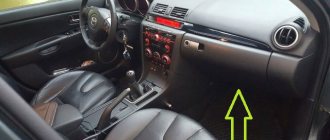
The number of elements in the main unit may differ from those shown and depends on the configuration, year of manufacture and country of delivery. The current purpose specifically for your car will be printed on top of the protective cover - the box. And if the generation is not suitable, study the description for the 3rd. We also note that the current schemes are suitable for the Jetta 2 model.
Change in fuse diagram after 1988
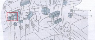
After 1988, fuses and relays were located as in the figure.
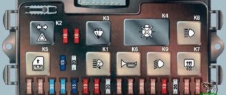
Decoding of PP values on a 2nd generation VolksWagen Golf.
| Electrical circuit or device | Denomination, A | Color | № |
| Electric motor of the engine cooling system fan | 30 | Green | 1 |
| Brake light bulb, tail light | 10 | Red | 2 |
| Car radio, cigarette lighter, clock in the instrument panel, interior lighting | 10 | Red | 3 |
| Emergency button | 15 | Blue | 4 |
| +12V fuel pump power supply | 15 | Blue | 5 |
| Front fog lights | 15 | Blue | 6 |
| Side light bulb, right side tail light | 10 | Red | 7 |
| Side light bulb, left side tail light | 10 | Red | 8 |
| Headlight high beam bulb, left side | 10 | Red | 9 |
| Headlight high beam bulb, right side | 10 | Red | 10 |
| Windshield wipers, headlight washer motor, windshield washer motor | 15 | Blue | 11 |
| Rear view window wiper, rear view window washer motor, electric exterior rear view mirror, engine coolant level indicator | 15 | Blue | 12 |
| Heated rearview glass, heated rearview mirror | 20 | Yellow | 13 |
| Interior heating fan drive | 20 | Yellow | 14 |
| Automatic transmission selector light, reverse gear light | 10 | Red | 15 |
| High pitch horn | 15 | Blue | 16 |
| Fuel supply interrupter for the internal combustion engine, heating of the intake manifold, PU of the carburetor internal combustion engine | 10 | Red | 17 |
| Low-pitched horn, heated front car seats, handbrake indicator | 10 | Red | 18 |
| Turn signal bulbs, front and rear | 10 | Red | 19 |
| Front fog lights, rear license plate light, glove compartment light | 10 | Red | 20 |
| Right low beam bulb in the headlight | 10 | Red | 21 |
| Left low beam bulb in headlight | 10 | Red | 22 |
| Relay connector description | Note | Designation on the diagram | |
| Reserve connector | I | ||
| Air heating in the intake manifold | Carburetor internal combustion engine | II | |
| Fuel pump | Single injection | ||
| Pre-heating plugs | Diesel internal combustion engine | ||
| Front seat belt buzzer | Diesel internal combustion engine | III | |
| Gear selector | Automatic transmission | IV | |
| Air conditioning compressor | V | ||
| Two-tone horn | VI | ||
| Front fog lights | VII | ||
| Power relief of terminal X | VIII | ||
| Reserve connector | IX | ||
| Headlight washer | X | ||
| Rear window wiper and washer motor | XI | ||
| Emergency crew | XII | ||
| Seat belt buzzer | XIII | ||
| Heated rear view glass, engine oil pressure indicator, seat belts | XIV | ||
| Windshield washer motor | XV | ||
| Adjusting idle speed | Single injection | XVI | |
| Reserve connector | Air conditioner | XVII | |
| Electric drive of the internal combustion engine cooling radiator fan | Carburetor internal combustion engine | XVIII | |
| Coolant level indicator in internal combustion engine | Diesel internal combustion engine | XVIII | |
| Reserve connector | Window lifters | XIX | |
| Heated driver's seat | XX | ||
| Heated front passenger car seat | XXI | ||
| Fuel supply switch | Carburetor | XXII | |
| Reserve connector | XXIII | ||
| Reserve connector | XXIV |
General purpose relay
Relay (000 953 227 A) - Relay for comfort turn signalsRelay 53 (141 951 253 B) - Horn relay, Fog light relay, Relay for fuel pump (diesel, 4Motion), Relay 79 (191 927 841) - Luggage lid relay compartmentRelay 87 (191 957 917 A) - Freewheel lock control unitRelay 100 (7M0 951 253 A)
— Relay with normally open contactRelay 103 (357 911 253) — Glow plug relay (diesel)Relay 109 (1J0 906 381 A) — Fuel pump relayRelay 147 (1H0 959 142) — Radio/telephone relayRelay 167 (191 906 383 C) — Relay with normally open contact for fuel pumpRelay 175 (3A0 927 181)
— Starter activation relay for AKPRRelay 181 (1J0 959 485) — Radiator fan shutdown delay relayRelay 185 (3B0 911 251) — Relay with normally open contact (Starter interlock switch) Relay 192 (1J0 955 531 A) — Windshield washer intermittent mode control unit/ windshield wiper for vehicles with rain sensorRelay 206, 444 (1J0 927 841)
— Relay with normally open contact for vehicles with electronic support system. well. stable ESPRelay 393 (4B0 919 471 A) - Burnt-out lamp monitoring relayRelay 377 (4B0 955 531 A) - Intermittent wiper control unitRelay 389 (4B0 955 531 C) - Intermittent wiper control unitRelay 404 (7M0 951 253 C)
— Universal relay (APF) Relay 407 (1J0 947 221 A) — Luggage compartment lid control unit for vehicles without central locking Relay 409 (191 906 383 C) — Fuel pump relay Relay 450, 452 (1J0 907 487 B) — Multifunction steering control unit wheelsRelay 456 (3U0 941 597 A)
Change in fuse diagram after 1988
Decoding of PP values on a 2nd generation VolksWagen Golf car after 1988.
| Protected electrical circuit, system or device | Fuse rating, A | Color coding | Number on the diagram |
| Right low beam bulb in the headlight | 10 | Red | 1 |
| Left low beam bulb in headlight | 10 | Red | 2 |
| Rear license plate light, instrument panel light bulbs | 10 | Red | 3 |
| Glove compartment light | 15 | Blue | 4 |
| Windshield wipers, windshield washer motor | 15 | Blue | 5 |
| Electric motor of the engine cooling system fan | 20 | Yellow | 6 |
| Side light bulb, left side tail light | 10 | Red | 7 |
| Heated rear view glass | 20 | Yellow | 8 |
| Front fog lights | 15 | Blue | 9 |
| Headlight high beam bulb, right side | 10 | Red | 10 |
| Headlight high beam bulb, left side | 10 | Red | 11 |
| High pitch horn | 10 | Red | 12 |
| Heated washer jets, rear license plate light | 10 | Red | 13 |
| Diesel fuel supply interrupter | 10 | Red | 14 |
| Dashboard | 15 | Blue | 15 |
| Emergency button | 10 | Red | 16 |
| Not used | 17 | ||
| Engine cooling radiator fan drive, air conditioning compressor | 30 | Green | 18 |
| Brake light bulb, tail light | 10 | Red | 19 |
| Interior light bulb | 15 | Blue | 20 |
| Car radio, cigarette lighter | 10 | Red | 21 |
| Relay connector description | Note | Designation on the diagram | |
| Air conditioning compressor | I | ||
| Rear window wiper and washer motor | II | ||
| Ignition system controller | III | ||
| Power relief of terminal X | IV | ||
| Coolant level indicator in internal combustion engine | V | ||
| Emergency crew | VI | ||
| Headlight washer | VII | ||
| Adjusting windshield wiper modes | VIII | ||
| Seat belt buzzer | IX | ||
| Seat belt buzzer | X | ||
| Two-tone horn | Jumper | XI | |
| Pre-heating plugs | Diesel internal combustion engine | XII | |
| Electric drive of the internal combustion engine cooling radiator fan | XIII | ||
| Air heating in the intake manifold | XIV | ||
| Hydroelectric ABS unit | XV | ||
| ABS system controller | XVI | ||
| Reserve connector | XVII | ||
| Reserve connector | Seat adjustment | XVIII | |
| Automatic transmission | XIX | ||
| Plug Controller | Diesel internal combustion engine | XX | |
| Power window motor | XXI | ||
| Reserve connector | ABS system | XXII | |
| Reserve connector | Air conditioning compressor | XXIII | |
| Reserve connector | Electric window drive | XXIV |
Features of replacing fuses in Golf 2
Procedure
To replace an element in the fuse box in a Golf 2, you must follow the following procedure:
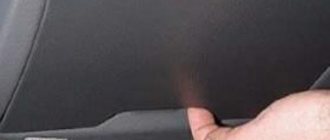
- Remove the cover from the block.
- Identify the faulty element by the melted walls and remove it using plastic tweezers.
- Insert a new part in accordance with the pinout of the fuse box in Golf 2. The fuse must be designed for the same amperage, which can be determined by the color and special inscription on the holder.
- Close the block with a lid.
If the new fuse quickly blows again, the corresponding electrical circuit must be carefully checked for overloads.
You cannot replace a damaged element with wire or other improvised materials. This may result in equipment failure or even a fire in the unit. For safety reasons, it is best to keep a small set of spare fuses in your car at all times. For this purpose, special fastenings are provided in the block.
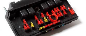
Appearance of fuses in Volkswagen Golf 2
Recommendations
Recommendations for replacement:
- Before starting work, it is advisable to turn off the electrical circuit in which the fuse has failed.
- It is not recommended to use grips that are too hard as they can scratch the contacts.
- If a constantly blowing fuse controls the operation of several circuits, you need to alternately connect one circuit to it and check it for errors. Only in this case will it be possible to find the true cause of the malfunction.
- Using a fuse with a higher amperage may cause damage or fire.
Video “Indicator fuse, demonstration of operation”
In this video you can clearly learn about the safety devices in the Volkswagen Jetta.
Almost the entire system of Volkswagen Jetta power circuits, on which the operation of the vehicle’s equipment depends, is protected by fusible contact elements, which are combined into a so-called fuse block. Through relays, which are also included in this block, such energy consumers are connected as:
- lighting lamps;
- electric cooling fan motors;
- fuel pump, etc.
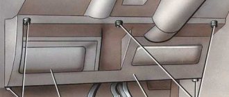
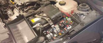
This unit and its serviceability are of particular importance for the stable operation of the main systems of the Volkswagen Jetta model. That is why these contact elements are combined and placed in a special mounting block. According to the instructions, it is located in the interior of the Volkswagen Jetta, on the left side of the instrument panel. There is a top shelf, which in turn consists of:
- lower casing of the instrument panel;
- fixing screw;
- instrument panels;
- cover protecting the unit.
This is where the block is located, where in case of a malfunction you need to look. As a rule, a faulty or burnt-out contact element will give itself away. It will have a melted metal part with a black coating. It is also possible that the colored case will be distorted.
Additional fusible elements
In some versions of Volkswagen Golf 3rd generation vehicles, additional fuses may be used. The following additional elements are used in the interior fuse and relay module:
- rated 30A - power supply to the ABS system relay;
- rated 30A - power supply to the relay of the hydroelectric unit of the ABS system;
- rated 10A - air conditioning compressor for cars without climate control;
- rated 30A - interior ventilation motor with the ClimaTronic system;
- with a nominal value of 5A - controller of the ClimaTronic system;
- rated 5A - +12A power supply to the on-board network of a towed trailer.
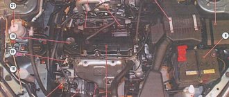
For a diesel internal combustion engine, an additional PP for the engine warm-up system is used, with a rated current of 60 A. It is located separately, on the engine panel under the hood.
Leaky cylinder head gasket
This malfunction does not occur often, but, in addition to deteriorating the performance of the standard heating element, it threatens significant problems for the power unit. Diagnosing the problem is easy. If an antifreeze leak is accompanied by a change in exhaust color from clear to solid white, this indicates that fluid is entering the cylinders and then into the muffler. A leaking BC head gasket seal is a serious problem because coolant will also enter the lubrication system, reducing the viscosity of the engine oil, which can significantly reduce engine life. Therefore, if a malfunction is detected, the gasket should be replaced as soon as possible. This procedure is quite responsible, but it can be done independently. If you have no experience in disassembling the cylinder head, it is better to turn to specialists to avoid mistakes typical for beginners.