The Starline A91 security system, equipped with an automatic engine start module, provides reliable protection for vehicles with any type of power unit and transmission. To transmit control commands, an interactive authorization algorithm with a cryptographic code and an individual encryption key is used, which excludes intelligent electronic hacking.
General description of the alarm
The StarLine A91 Dialog alarm system is a modern car security system with a “Quick Dialog” radio control dialogue code and an engine auto-start function. “Quick dialogue” - a control code with individual encryption keys eliminates intelligent electronic hacking.
She is a representative of the budget family of the manufacturer. Despite this, inter-key fob communication is carried out via 8 channels from the transceiver-transmitter. Security is ensured by conversational pattern communication, the floating channel method and 128-bit code. Each time a signal is sent to the key fob or vice versa, the Starline anti-theft system automatically selects an alternative frequency.
Despite the narrow spectrum of transmission of the transceiver and channel-by-channel sending of a selective type signal, the developers of the a91 worked with the communication range of the a91 key fob with the main unit. A solution of this level, known by the technical term “frequency hopping spread spectrum technique,” is the first in the world to be used in an alarm control system and is a very significant complication of any code-breaking attempts.
The anti-theft system from Starline model a91 provides for installation on any car. We get a budget option, a very reliable, simple and universal security system.
Detailed operating instructions for car alarm Starline A91
Installation of the complex must be carried out by a trained specialist at a specialized enterprise.
A car alarm is a technically complex device that requires implementation in the vehicle's on-board electrical circuits and adaptation in its electronic control components. StarLine A 91 is a modern system for ensuring comprehensive vehicle safety, designed and manufactured at a high technological level with the widespread use of innovative technologies.
Alarm characteristics
Security functions of STARLINE A91
- silent security mode, as well as a mode with a sound signal;
- option to automatically turn on the security system;
- arming without using a key fob and with the engine running;
- performing automatic diagnostics when the security mode is turned on;
- disarming with or without sound;
- disabling engine blocking in two stages.
The main distinguishing feature of this alarm among others in the same price category can be noted:
- the presence of a convenient interactive 128-bit control code, which cannot be penetrated by any of the known code grabbers (devices that allow reading the system code);
- ergonomic and resistant to extreme weather.
- for such a price it will be difficult to find a more frost- and heat-resistant security device for your car, and the battery capacity will allow the alarm to operate in security mode for one and a half to two months;
- you can be sure that in the signal coverage area, which is from 800 to 1000 meters, there can be no interruptions in the operation of the alarm system - all radio interference that often occurs in urban environments will be bypassed using a specialized transceiver;
- the alarm and key fob work with modern software, which significantly increases the speed of the system than on more outdated models
The functionality of the Starline A91 with auto start corresponds to all the stated distinctive features - modern software coupled with hardware properties ensures productivity and a high degree of vehicle protection. All functions can be divided into two parts: security functions of the device and service functions (mainly associated with the use of a key fob). All service functions will be described in detail in the corresponding subheading.
No response to key fob
If the Starline A91 key fob does not respond to button presses and, of course, it has a working battery installed (the display is displayed clearly and in contrast), make sure that:
- The key fob sees the car and it is in the zone of reliable reception. Near sources of strong interference (for example, under power lines), in a large parking lot, the alarm can significantly reduce the two-way communication range necessary for the operation of the dialogue code used by Starline.
- The car responds to the spare key fob (that is, the source of the problem is not in the alarm itself).
You should try to re-register an unrecognized key fob as stated above. Breakdowns or malfunctions of the key fob's software will require its repair (you can re-solder broken buttons or the antenna yourself if you have sufficient soldering skills; reflashing the key fob yourself is impossible, since the manufacturer does not provide information on connecting the programmer and the firmware itself to the public) or replacement.
The complete or partial absence of icons on the screen when the backlight is working normally indicates problems with connecting the screen to the main board of the key fob; it needs repair. However, even completely physically turning off the display will not prevent the key fob from controlling the alarm.
Scope of delivery of the Starline A91 alarm system
Delivery set of Starline A91
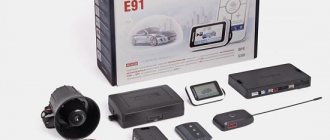
Starline a91 dialog is supplied in an expanded package, consisting of:
- Anti-theft system installation guide.
- Instructions for use and operation.
- Remote control equipped with a liquid crystal screen and having a feedback function.
- Battery for installation in this remote control.
- The package includes one more, spare key fob. It has a feedback option, but it does not have a screen.
- A control module that performs all functions.
- Antenna adapter with module.
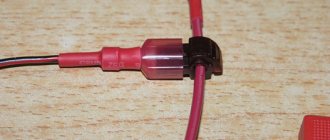
- Two-level kick controller.
- Double-sided tape designed to secure the transceiver.
- Case for the main remote control with screen.
- Power cable for connecting the transceiver.
- Wire for connection to the sensitivity controller control unit.
- Button for installation on the hood.
- Service key.
- Temperature controller. Used to remotely start the power unit at a certain temperature.
- Main cable with 18-pin plug. Used to connect main components.
- Power wire for power supply and electrical circuits used to remotely start the motor.
- The cable for connecting to the central locking is equipped with a six-pin connector.
- Light.
Video review of the configuration:
Enabling start based on engine temperature
More relevant during cold weather is automatic start based on engine temperature. Unlike the previous method, the engine will not start if it is warm and there is no need to warm it up. This option is programmed as follows:
- turn off the ignition, press the Valet key six times;
- turn on the ignition, listen to six beeps, click Valet four more times;
- Now the first button on the remote control will set the parameter -5 degrees, the second - minus 10, the third - minus 18. A long and then short press of the first button is responsible for setting the parameter - 25 degrees Celsius.
Important functions of the Starline A91 alarm system
What areas does Starline A91 protect:
- Car motor. Protection is carried out using a conventional or digital relay.
- Car doors, luggage compartment, hood, and handbrake. Protection is ensured thanks to limit switches.
- Ignition system. For protection, a control input is made into the ignition circuit.
- Car body. All impacts on it are recorded by the sensitivity controller.
- An additional controller is used to protect and detect movement inside the cabin.
Anti-theft device options:
- activation of an alarm pulse when the controller is turned on if the installation is operating in security mode;
- transmission of warning signals from the unit to the remote control;
- immobilizer option, thanks to which the internal combustion engine is blocked;
- turbo timer option;
- anti-robbery function;
- the process of disabling the motor blocking is carried out thanks to a two-level algorithm;
- use of a personal emergency shutdown password, the function is programmable;
- If the anti-theft system is disconnected and dismantled, the power unit is blocked.
Self-diagnosis and fault detection functions:
- the system monitors the operation of all security controllers; if non-working sensors are detected, the alarm turns them off and notifies the car owner;
- the alarm system determines its status using the LED indicator, information about this is transmitted to the control panel;
- the system records impacts on the car body and determines the reason for the activation of the siren in one of the existing zones and transmits information about this to the control module;
- when the siren is activated, the device will warn the car owner with sound signals on the remote control;
- Diode indication is used to determine the serviceability of limit switches.
What service functions does this model have:
- silent protection option;
- putting the car on protection with the engine running;
- the ability to silently activate and deactivate protection;
- option to disable and activate security without using the remote control;
- if an accidental shutdown occurs, the installation will activate the security function;
- if the system is activated, the car owner can remotely disable the controllers at different levels;
- possibility of remote control of central locking;
- option for central locking control using the ignition switch;
- two-step opening of door locks based on two signals;
- if necessary, the car owner can configure the Comfort option;
- the presence of four auxiliary control channels;
- interior lighting control option;
- Panic mode;
- car search option;
- service mode;
- call function from vehicle;
- This alarm model provides protection against accidental activation of the buttons on the remote control;
- The key fob with feedback can operate in sound and vibration modes;
- function of separate temperature display in the engine compartment of the car, as well as in its interior;
- The control panel with LCD display operates in energy saving mode;
- the ability to remotely program remote controls and delete old ones from the control unit’s memory;
- the car owner can remotely configure the modes and options of the anti-theft system;
- if necessary, you can quickly reset the entire system configuration to the factory one;
- It is possible to additionally install a GSM module.
2. Protected areas of the car
Each alarm system is designed to protect certain parts and components of the car. They are called security zones. And each of them is responsible for a certain part of the alarm system. In the Starline A91 security system, these are a conventional and digital relay (not supplied), push-button switches, an ignition circuit control input and various sensors. Due to this, it is possible to determine exactly where there was an attempt to break into the car and obtain information about the nature of the threat.
Description of the capabilities of the Starline A91 alarm key fob
Self-diagnosis and indication of operating modes:
- Automatic monitoring of security sensors with disabling faulty ones and reporting this
- Indication of alarm status by LED and on the key fob display
- Indication of the reasons for alarm activation in 9 security zones
- Indication of a faulty zone when the security mode is turned on
- Indication of the fact that the alarm has been triggered by sound signals
- LED indication of serviceability of limit switches
Alarm service functions:
- Silent security mode
- Security mode with engine running
- Silent activation/deactivation of security mode
- Turning on/off security mode without a key fob
- Bypassing the door area for the duration of the interior light extinguishing delay
- Automatic return to security mode in case of accidental shutdown
- Remote disabling of sensors by level in security mode
- Remote control central locking
- Central locking control from the ignition switch
- Two-step door unlocking
- Double-pulse door unlocking
- Possibility of implementing the “comfort” function
- 4 additional control channels
- Car interior lighting control
- Panic mode
- Car search mode
- Service mode
- Call mode from car
- Protection against accidental pressing of key fob buttons
- Sound and vibration modes of operation of the key fob with feedback
- Separate temperature display in the cabin and under the hood of the car
- Energy saving mode of key fob with liquid crystal display
- Remote programming of new and erasing lost key fobs
- Remote programming of alarm modes and functions
- Quick reset of programmable functions to factory settings
- Ability to work with GSM modules StarLine M20 and StarLine M30
- Current time display, alarm clock, timer
Advantages and disadvantages
The advantages of the system include:
- Advanced functionality allowing the owner to select the necessary service or security options.
- Work with signals or in “quiet” mode.
- Automatic engine start allows you to preheat or cool the car interior. The complex is capable of operating on vehicles equipped with a push-button start system for the power unit.
- Transmitted commands are protected by a dialogue code that does not allow the signal to be intercepted and decrypted.
- Customizable key fob with the ability to program additional remote controls.
- An extended set of technical documentation explaining the installation and configuration methods.
- Possibility of expanding the complex with additional sensors and modules.
- Versatility of design.
- Affordable price.
Disadvantages of the security complex:
- Inconvenient temperature intervals during automatic start.
- It is not possible to connect the complex to a digital bus and combine control of standard and additional alarms with one key fob.
- Forced autorun requires manipulation of 2 keys.
- There are problematic components that are replaced under warranty.
- Fragile plastic control key fob. The buttons begin to fall inward over time.
- The alarm system is a budget product. Therefore, the design contains simplified and cheaper components.
Setting up autostart alarm Starline A91
- Move the gearshift knob to the neutral position (turn off all gears);
- Turn off the ignition and remove the key from it (the engine must be on);
- Apply the parking brake.
- Close all doors tightly, as well as the hood and trunk lid;
If any step is missed, remote launch is not possible. But with proper preparation of the car (the engine is turned off by the alarm itself), it can be started from the remote control in different ways.
- Press and hold button No. 1 for three seconds and after the sound signal quickly press button No. 3:
Periodically starting the engine from the key fob:
This function is especially relevant in winter, when periodic warming up of the engine is required. The starline a91 key fob can automatically start the engine to warm up (after 2, 3, 4, 24 hours).
How to configure autorun by time, temperature
The Starline A91 Dialog alarm can be configured in such a way that it will automatically start the engine based on air temperature (usually sub-zero) or after a specific period of time.
Activate autostart mode based on temperature
This function will work if certain conditions are met:
- if there is a temperature sensor;
- from the place of its installation;
- serviceability of the sensor itself.
Activated by long pressing button 3 (star) until a sound signal appears from the key fob - it should beep once. The leftmost icon (1) at the bottom of the screen will blink on the display. By short pressing button 3, we move through the menu to the third position from the left (square 3) with the thermometer symbol.
After making sure that the desired function is activated, press button No. 1 on the case to activate this mode (this mode is turned off by pressing button 2 on the case), and in place of the clock readings a critical value of the engine temperature will appear after which it will autostart.
After the temperature value has been displayed, there is no need to press anything - after 8-10 seconds the remote control itself will beep and the clock will appear on the display again, and the third icon (with a thermometer) will remain dark. The state of this icon shows whether the autorun mode is running based on temperature: dark - the mode is active, light - reset.
Autostart by time
To enable this function, you need to select icon 2 on the display. The car will blink its headlights once, and a melodic signal will sound on the key fob. Now, after a time specified by the owner, the alarm will periodically start the engine.
If after the first attempt the car does not start, a second one will follow. In this case, the starter cranking time will be increased by 0.2 seconds. The timer is designed for 4 attempts to start the engine. If even after the fourth attempt the engine does not start, the sound signal on the key fob sounds. To set the engine warm-up time, the sequence of actions is as follows:
- Press and hold button No. 3 on the key fob (asterisk) for a long time.
- The key fob will beep briefly, but keep the button pressed, after the second sound signal, release the button;
- The leftmost icon (1) on the panel will blink;
- Briefly press button No. 3 to move to the fan icon;
- With one short press of button No. 1, the key fob will play a melody;
- Wait about ten seconds until the key fob beeps and the fan icon remains darkened;
- The interval start function is activated.
It is turned off in the same way, but the choice is confirmed by button No. 2 (open lock). When the engine starts successfully, an image of exhaust gases will appear on the screen. The car itself will blink its headlights 3 times and beep three times
Separately, it should be said about the engine start option:
- Remote engine start/stop - Remotely extend the operation of a running engine
- Automatic engine start based on temperature, alarm clock, timer every
- Selecting transmission and engine type
- Monitoring the operation of the internal combustion engine relative to the state of the generator or voltage changes
- option for automatic protection against twisting of the starter device when starting the internal combustion engine;
- determining the operating time of a running engine on the key fob
Always remember that section 12.8. The traffic rules state: “The driver may leave his seat or leave the vehicle if he has taken the necessary measures to prevent the vehicle from moving spontaneously or being used in the absence of the driver.”
Before using the StarLine A91 car alarm, follow these rules:
- Always park your vehicle in an open, well-ventilated area
- Always set the vehicle's parking brake, which must be in good condition and prevent the vehicle from moving.
- When leaving the vehicle, be sure to place the automatic transmission control lever in the “PARK” position and the manual transmission shift lever in the neutral position.
- If your car uses a manual transmission, then before turning on the remote or automatic engine start function, be sure to complete the preparation procedure for starting the engine - “soft neutral”
- Never start a vehicle without the driver present or if anyone is in front of or behind the vehicle.
- Never give car alarm control key fobs to children or other persons without first reading these instructions.
- On cars with a manual transmission, it is not recommended to perform remote or automatic engine starting if the car is out of sight and the car alarm user is not able to control the engine starting process.
- Make sure the car is in good condition (make sure there is enough fuel, oil, coolant, etc.)
How to install it yourself
For self-installation you will need:
- carefully study the documentation for the Starline A91 alarm system;
- know the structure of the car's electrical system;
- have minimal skills in installing electrical devices.
Recommendations for placement and installation
A short guide to placing and switching elements:
- It is recommended to place the central controller inside the car in a hidden cavity that is not exposed to moisture. Usually the unit is installed deep in the instrument panel, attached to a power steel frame using plastic ties or self-tapping screws. You can use 2-sided tape. The fixed unit should not move under the influence of vibration loads that occur during vehicle operation. When installing, you should install the unit with the connector block facing down, which will reduce the risk of condensation drops flowing inside.
- Place the receiver and transmitter housing on the windshield or inside the instrument panel. In this case, it is necessary to ensure that there are no metal body elements at a distance of less than 50 mm from the antenna. The range of operation of the control panels depends on the correct installation of this element. The controller includes a temperature sensor. For the element to operate correctly, it must be located away from heat sources (air conditioning ducts, direct sunlight).
- The standard siren is mounted in the engine compartment in a place isolated from heating or flooding with water. Additional waterproofing is provided by installing the socket of the device downwards. The wiring and siren should be located as far as possible from the bottom of the machine, which will reduce the risk of damage to parts by an intruder.
- The impact sensor is mounted on the body frame. The installation point must provide access to the sensitivity adjustment potentiometer.
- If you plan to use automatic start, then you need to install a second sensor under the hood. To attach an additional sensor, bolts on the crankcase or engine block head or any bracket are used. Installing the unit on the motor housing allows you to more accurately determine the temperature of the unit and ensures timely start-up.
- The control diode must be installed in a visible place on the instrument panel or the trim of the front pillars. Installation in a pre-drilled hole is allowed.
- The service button is located in a hidden place, providing quick access to the node. The part is located under the instrument panel or in the mounting safety block.
- Some vehicles require installation of additional switches under the panels of the hood and (or) trunk lids. The condition for normal operation is a gap between the contacts of at least 3 mm (in the closed state). An incorrectly installed and adjusted “limit switch” leads to false alarms.
- Wiring harnesses are laid at a distance from sources of radio frequency interference, which are elements of the ignition system. At the same time, the absence of contact with moving elements - pedals, climate control rods or gearbox - is checked.
Connection features
When installing and connecting the alarm system, it is necessary to take into account the design features of the car, which affect the settings of the central unit and the connection of wires. The joints must be connected by crimping with a special tube; the use of solder and organic fluxes is allowed. The joint points are protected with insulating tape or heat shrink tubing.
Some installers use wires that imitate the car's standard wiring harnesses for connections. This technique makes it difficult for an attacker to disable the device, but also complicates the further maintenance procedure. When replacing wires, you should take into account the appropriate cross-section, which should not be less than the original one. It is also not recommended to use wiring made of various materials (for example, copper and aluminum).
Step-by-step connection instructions with diagrams
General algorithm for connecting the wires of service elements to the central unit:
- Connect the radio transmitter mounted on the glass using a wire with a 5-pin connector.
- Lay the diode wire. It is installed in a 2-pin block located on the central block.
- Install the service key signal harness equipped with a 2-pin plug.
- Install the wiring for the shock sensor and additional sensor. The -12V signal must be supplied to the additional sensor simultaneously with the appearance of power at the negative output of the central unit. The type of signal processing from this device is programmable.
Schematic diagram of connecting elements
Connectors
Connect the wires of the power connector in accordance with the instructions as follows:
- The node with red insulation is supplied with +12V positive power, which comes from the battery terminal. It is allowed to insert the wire into the power circuits going to the ignition switch.
- The yellow wire, responsible for supporting the operation of the ignition system, should be connected to the IGN 15/1 point located on the lock. This section of the circuit is simultaneously used to control the sparking system.
- The existing accessory control output is connected to the ACC connector on the lock. The wire has a green protective coating.
- An additional control output must be connected depending on the programmed operating algorithm. Connection to the brake pedal limit switch is allowed (only if a start-stop button is installed). The wire is equipped with blue insulation.
- The black and yellow wire, which has an increased cross-section, is used to control the activation of the starter. It is connected from the starter side, always after the ignition switch.
- The last wire with black and yellow protection is designed to block the starter when the security is on and to protect against accidental activation when the engine is running.
Connecting the power plug responsible for autostart
A typical connection diagram for an 18-pin central block block is shown in the table:
| Protective coating color | Purpose | Note |
| Black | Negative signal, connects to the car body | There is a separate loop that is responsible for selecting the type of gearbox during autostart. If the car is equipped with an automatic transmission, then the part is preserved; if it is equipped with a manual transmission, it is cut. |
| Green-black | Direction indicators for one side | Load current no more than 7.5A |
| Green-yellow | Likewise for the other side | Identically |
| Grey | Siren control signal (positive pulse) | Allowable current 2A |
| Blue-black | Door lock microswitches connected to ground when opening | — |
| Blue-red | Door switches that provide a +12V signal when unlocked | — |
| Orange-gray | Signal from hood switch closing to negative when opening | — |
| Orange-white | Similar element of the trunk lid | — |
| Yellow-black | The negative output signal of additional channel 1 is used to control the trunk lid lock solenoid. To switch signals, a relay must be installed | The load current is not higher than 0.2A, supplied for 1 second. |
| Yellow-red | A similar element of additional channel 2. Designed to control 2-step opening of locks and control additional modules (via a relay) | It is possible to send an impulse lasting up to 1 minute; it is possible to turn off the signal from the key fob |
| Yellow-white | Identical, used for channel 3, which controls additional equipment | Likewise |
| Blue | Channel 4, used to turn on interior lighting or control the operation of electric window motors | Current up to 200 mA |
| Black and white | A negative signal that determines the state of the security system. It is necessary to control the alarm system, as well as to operate the immobilizer and enable the anti-theft mode. The circuit operates through an unloading relay | Likewise |
| Pink | An additional wire for the complex status, activated at the moment of automatic engine start and when the turbo timer is running. The output can be used to bypass engine locking systems during a remote warm-up cycle | Likewise |
| Black-red | External programmable engine blocking, operated via a contact module. | Likewise |
| Gray-black | Universal monitoring of the operating parameters of the power unit, the input circuit has a resistance of at least 200 kOhm. Connects to tachometer sensor, generator or on-board network (voltage control) | — |
| Orange-violet | Checking the condition of the parking brake lever or pedal. When the negative signal disappears due to the handbrake being released or the pedal being pressed, an alarm will be triggered. When the engine warms up, the operation will additionally stop. | — |
A general view of the wire connection is shown in the diagram:
18-pin connector of the Starline A91 block
Alarm circuits
The alarm circuits are connected as follows:
- To block the engine start, use an additional relay connected to the open circuit. The relay type is selected when setting up the central unit.
- Activate the blocking relay built into the unit by connecting it to the open circuit between the starter and the ignition switch.
- When using an additional radio relay, configure the device individually (write the device code into the alarm memory).
- If it is necessary to use the function of “polite” interior lighting, the unit is connected to a special unloading relay cut to the lighting lamp. The low beam headlights are connected in the same way, which provides a comfortable illumination zone for the driver.
The Starline A91 dialog complex allows operation in conjunction with security and search modules M20 and M30.
Cabin lighting control
Connecting the trunk lid lock drive
Connection diagram for engine blocking with external relay
Activating the built-in start interlock
To the central locking system
The security complex is equipped with built-in relays that allow you to control the standard central locking. The contact groups of the control modules are connected to a block equipped with 6 pins. The circuits and contacts are designed for a maximum current of 15A, while the duration of the control pulse is a programmable parameter.
Possible connection options are shown in the diagrams:
General switching diagram
Connection diagram for 2-wire actuators
Control of pneumatic lock drive system
Connection features for 2-step unlocking of locks
Setting up the Starline A91 alarm turbo timer
The turbo timer can act as an independent element, which is a unit installed under the torpedo with a connection to the ignition switch. Or maybe as part of the Starline car alarm system. The latter option is considered the most convenient, since it does not require synchronization of the alarm and turbo timer, minimizing the risk of security system failure.
After installation work, it is recommended to check the functionality of the function and make the necessary settings. The turbo timer is configured according to two parameters:
- depending on the desired engine idling time;
- depending on the temperature of the turbine assembly.
Despite the uniform principle of operation, there are some nuances in how to set up the turbo timer. Even models from the same line may have differences in settings.
Activating the turbo timer
After the settings have been made, it is possible to activate the turbo timer in three different scenarios:
- automatically after applying the parking brake and turning off the ignition;
- using the key fob after applying the parking brake, locking the doors and turning on the security mode;
- after applying the parking brake.
A car enthusiast can choose how to turn on the turbo timer on Starline, based on the preferences and degree of convenience of each option.
Often the instructions do not indicate how to disable the turbo timer. It is assumed that disabling a mode is similar to activating it, but in reverse order. If the function is not needed, it is enough to deactivate the icon indicating the turbo timer using the service buttons of the key fob.
Possible problems
After installing the alarm and making all the settings, it happens that the turbo timer does not work. There may be several reasons for this.
- The alarm was not connected to the engine start circuit correctly;
- Factory and service settings do not allow activating the turbo timer mode;
- The parking brake of a car with a manual transmission is disabled or the Parking mode is not activated in cars with an automatic transmission;
- TURBO mode is not activated on the key fob screen.
Each of the options is a connecting link in the process of connecting the mode, so when wondering how to install a turbo timer on Starline, you need to take into account the manufacturer’s requirements and check the serviceability of the settings made. Only after this can you effectively use the turbo timer function, which ensures proper operation of the exhaust system components and protects the turbocharged engine from breakdowns.
Key fob doesn't open doors
The instructions for the Starline A91 key fob indicate that to unlock the doors on the main or additional key fob, button 2 is briefly pressed. The lack of a correct response is possible in two ways:
- the car does not disarm and does not open the doors;
- The car is normally disarmed, but the doors do not open.
In the first case, perform the same checks as in the previous section of the article. A common problem with the main key fob is the button moving away from the board due to too strong pressing, since it is soldered to the board at a right angle, while on the additional key fob the buttons only press against the board when pressed.
If the doors do not open during normal disarming (that is, everything is fine with the connection), then you need to check:
- On vehicles without standard central locking: wiring to additionally installed door actuators, fuses on the green and blue wires from the 6-pin connector of the central alarm unit.
- On cars with standard central locking - connect the alarm circuits to the standard wiring according to the installation map for a specific car model.