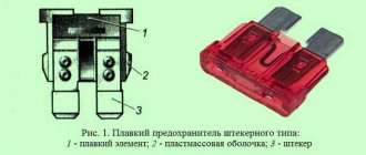
The wiring harnesses of the front panel, engine compartment and rear harness of the “Seven” are connected through the VAZ 2107 fuse box . In addition to connecting electrical wiring branches, it performs the important function of protecting against overload and short circuit. Let's figure out what a fuse box is, where it is located and what each of its elements is responsible for.
Fuse box location
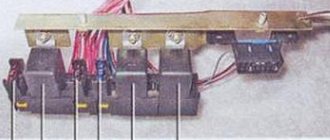
Most of the fuses that protect the electrical wiring of the “seven” are located in a single block located under the hood of the car. In addition to fuses, the block contains a group of relays that are responsible for turning on electrical appliances, for example, heated rear windows or headlights.
The VAZ 2107 mounting block is located under the hood near the windshield, opposite the passenger seat. Depending on the year of manufacture, the “sevens” were equipped with two types of fuse blocks: “old” and “new”. The designs of both types of blocks have slight differences, so their features and electrical circuits should be considered separately.
Important: regardless of the type of fuel supply (carburetor or injector), the circuits of one (old or new) type of “seven” fuse box are the same. Both types of blocks can be installed on injection and carburetor models.
Cooling fan malfunctions and their symptoms
Taking into account the fact that the fan is an electromechanical unit, the operation of which is ensured by a separate circuit, its malfunctions can manifest themselves in different ways:
- the device does not turn on at all;
- the electric motor starts but runs constantly;
- the fan starts working too early or too late;
- During operation of the unit, extraneous noise and vibration occur.
The fan doesn't turn on at all
The main danger posed by a broken cooling fan is overheating of the power plant. It is important to control the position of the arrow of the temperature indicator sensor and feel the moment the device turns on. If the electric motor does not turn on when the arrow reaches the red sector, most likely there is a malfunction of either the device itself or the elements of its circuit. Such breakdowns include:
- failure of the armature winding, wear of the brushes or commutator of the electric motor;
- sensor malfunction;
- break in the electrical circuit;
- fuse blown;
- relay failure.
Constant fan operation
It also happens that the device’s motor turns on regardless of the temperature of the power plant and runs constantly. In this case, the following may occur:
- short circuit in the fan electrical circuit;
- sensor failure;
- relay stuck in the on position.
The fan turns on early, or, conversely, late
Untimely turning on of the fan indicates that the characteristics of the sensor have changed for some reason, and its working element does not respond correctly to temperature changes. Similar symptoms are typical for both carburetor and injection “sevens”.
Extraneous noise and vibration
The operation of the cooling fan of any car is accompanied by a characteristic noise. It is created by the impeller, cutting the air with its blades. Even merging with the sound of the car’s engine, in the “seven” this noise is clearly audible even from the cabin. This is the norm for our cars.
If the rotation of the fan blades is accompanied by a hum, creaking or whistling, the front bearing or support sleeve in the cover may have become unusable. A cracking or knocking sound indicates contact of the impeller with the inner edge of the frame in which the electric motor is installed. This malfunction is possible due to deformation or misalignment of the fan blades. For the same reasons, vibration occurs.
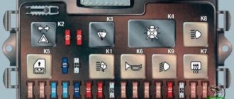
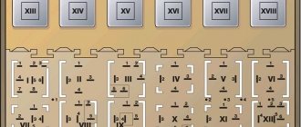
Old model VAZ 2107 fuse diagram
The “old” fuse box has 17 fuses. Each of them protects one or more electrical circuits. Purpose of fuses:
| Fuse number (rated current)* | Purpose of VAZ 2107 fuses |
| F1 (8A/10A) | Rear lights (reversing light). Reverse safety device. Heater electric motor. Heater fuse. Warning lamp and heated rear window relay (winding). Electric motor for rear window cleaner and washer (VAZ-21047) |
| F2 (8/10A) | Electric motors for wipers, windshield washers and headlights. Relay for wipers, windshield washers and headlights (contacts). Wiper fuse VAZ 2107 |
| F3/4 (8A/10A) | Reserve |
| F5 (16A/20A) | Rear window defroster heating element and its relay (contacts) |
| F6 (8A/10A) | Cigarette lighter fuse for VAZ 2107. Socket for portable lamp |
| F7 (16A/20A) | Sound signal. Radiator cooling fan electric motor. Fan fuse for VAZ 2107. |
| F8 (8A/10A) | Direction indicators in hazard warning mode. Switch and relay interrupter for direction indicators and hazard warning lights (in hazard warning mode) |
| F9 (8A/10A) | Fog lights. Generator voltage regulator G-222 (for car parts) |
| F10 (8A/10A) | Instrument cluster. Instrument panel fuse. Indicator lamp and battery charge relay. Direction indicators and corresponding warning lamps. Indicator lamps for fuel reserve, oil pressure, parking brake and brake fluid level. Voltmeter. Instruments of the carburetor electro-pneumatic valve control system. Parking brake warning light relay |
| F11 (8A/10A) | Brake light bulbs. Lamps for interior body lighting. Brake light fuse. |
| F12 (8A/10A) | High beam (right headlight). Headlight wiper relay activation coil |
| F13 (8A/10A) | High beam (left headlight) and high beam indicator lamp |
| F14 (8A/10A) | Side light (left headlight and right rear light). Indicator lamp for turning on the side light. License plate lights. Engine compartment lamp |
| F15 (8A/10A) | Side light (right headlight and left rear light). Instrument lighting lamp. Cigarette lighter lamp. Glove compartment lamp |
| F16 (8A/10A) | Low beam (right headlight). Headlight cleaner relay switching coil |
| F17 (8A/10A) | Low beam (left headlight) |
| * In the denominator for pin type fuses | |
Fan motor
The electric motor is the main component of the device. The VAZ 2107 used two types of engines: ME-271 and ME-272. In terms of characteristics, they are almost identical, but as for the design, it is somewhat different. The ME-271 engine has a stamped housing, i.e., non-separable. It does not require periodic maintenance, but in case of malfunction, it can only be replaced.
Not every fan motor can be disassembled
Design and characteristics of the fan motor
Structurally, the motor consists of:
- housings;
- four permanent magnets glued around the circumference inside the case;
- armatures with winding and collector;
- brush holder with brushes;
- ball bearing;
- support sleeve;
- back cover.
The ME-272 electric motor also does not require maintenance, but unlike the previous model, if necessary, it can be partially disassembled and attempted to be restored. Disassembly is carried out by unscrewing the tightening bolts and removing the back cover.
ME-272 has a collapsible design
In practice, repairing an electric fan is impractical. Firstly, you can only buy used spare parts for it, and secondly, a new device complete with impeller costs no more than 1,500 rubles.
Table: main technical characteristics of the ME-272 electric motor
| Characteristics | Indicators |
| Rated voltage, V | 12 |
| Rated rotation speed, rpm | 2500 |
| Maximum current, A | 14 |
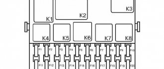
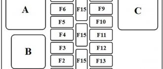
New VAZ 2107 fuse block diagram
On newer “sevens” a block with 17 fuses and 6 relays is installed. VAZ 2107 fuses on the “new” unit protect the following electrical circuits and devices:
- Reversing lamps, heater fan, rear window defroster warning lamp and relay, rear wiper motor and rear washer pump.
- Electric motor for front wipers.
- Reserve socket.
- Reserve socket.
- Power supply for heated rear window.
- Clock, cigarette lighter, power socket “carrying”.
- Signal and radiator fan.
- Turn signal lamps in emergency mode.
- “Fog lights” and a relay that regulates the voltage of the on-board network.
- Instrument panel lamps.
- Brake light bulbs.
- Right high beam headlight.
- Left high beam headlight, high beam warning lamp.
- Side lights (rear right, front left), license plate and engine compartment lighting.
- Side lights (rear left, front right), glove compartment and cigarette lighter lamps.
- Low beam (right lamp).
- Low beam (left lamp).
The relays of the new block perform the following functions:
- Heated rear window relay.
- Headlight cleaner and washer relay.
- Signal relay.
- Cooling system electric fan relay.
- High beam relay.
- Low beam relay.
Wires for connecting electrical appliances
| Connection type | Section, mm2 | Insulation color |
| Negative terminal of the battery - vehicle ground (body, engine) | 16 | Black |
| Starter positive terminal - battery | 16 | Red |
| Positive contact of the generator - plus battery | 6 | Black |
| Generator - black connector | 6 | Black |
| Terminal on the generator “30” – white MB block | 4 | Pink |
| Starter connector “50” – starter relay | 4 | Red |
| Starter Start Relay - Black Connector | 4 | Brown |
| Ignition switch relay - black connector | 4 | Blue |
| Ignition switch output “50” – blue connector | 4 | Red |
| Ignition switch connector “30” – green connector | 4 | Pink |
| Right headlight plug - ground | 2,5 | Black |
| Left headlight plug - blue connector | 2,5 | Green, gray |
| Generator output “15” – yellow connector | 2,5 | Orange |
| Right headlight connector - ground | 2,5 | Black |
| Left headlight connector - white connector | 2,5 | Green |
| Radiator fan - ground | 2,5 | Black |
| Radiator Fan - Red Connector | 2,5 | Blue |
| Ignition switch output “30/1” – ignition switch relay | 2,5 | Brown |
| Ignition switch contact “15” – single-pin connector | 2,5 | Blue |
| Right headlight - black connector | 2,5 | Grey |
| Ignition switch connector “INT” – black connector | 2,5 | Black |
| Six-pin block of the steering column switch - “ground” | 2,5 | Black |
| Two-pin block of the steering column switch - glove box illumination lamp | 1,5 | Black |
| Glove compartment light - cigarette lighter | 1,5 | Black |
| Cigarette lighter - blue block connector | 1,5 | Blue, red |
| Rear window defroster - white connector | 1,5 | Grey |
Useful: Lada Vesta VAZ-2180 diagram
Replacing fuses
Before replacing fuses there are two things you need to do:
- turn off the ignition;
- disconnect the ground from the battery.
Otherwise, a short circuit may occur during operation.
The procedure is as follows:
- remove the fuse box cover by releasing the fasteners;
- inspect the fuses and determine those in need of replacement (this can be seen by a broken fusible thread or black traces of its combustion);
- remove the fuse using pliers or special tweezers;
- insert a new fuse rated for the same current;
- close the lid.
Video
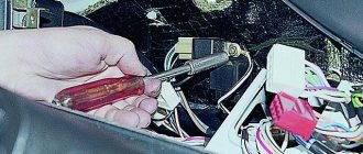
The video from user Konstantin Kalinnikov shows the process of removing an old-style fuse box.
Do you have any questions? Specialists and readers of the AUTODVIG website will help you ask a question
Was this article helpful?
Thank you for your opinion!
The article was useful. Please share the information with your friends.
Yes (75.00%)
No (25.00%)
X
Please write what is wrong and leave recommendations on the article
Cancel reply
Rate this article: ( 4 votes, average: 4.75 out of 5)
Discuss the article:
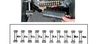
Replacing the fog light fuse
If the fog lights stop lighting, you should check the fuse installed in the passenger compartment. To replace it you need a screwdriver. The replacement procedure is as follows:
- remove two switches from the console (the place where the radio is installed) using a flat-head screwdriver;
- use a screwdriver to press out the two latches and pull out the plastic insert from the console;
- pull out the fog light fuse housing;
- open the case and replace the fuse;
- Replace the insert and switches.
Replacing the fuse box on a VAZ 2107
VAZ 2107 fuses (injector and carburetor) are installed in standard interchangeable blocks, so replacing them is not difficult. The power supply unit can only be replaced with a unit of a similar type (old or new). This is done like this:
- disconnect the ground from the battery;
- remove the air filter housing;
- unplug the wiring harness connected to the fuse box, which is located at the bottom of the power supply unit;
- dismantle the shelf located in the cabin under the “torpedo”;
- remove the glove compartment housing;
- disconnect the second wiring harness from the power supply unit;
- unscrew the power supply bolts (the right bolt is hidden, it is not immediately visible);
- remove the fuse box;
- install a new fuse box;
- tighten the fastening bolts;
- connect the harness coming from the passenger compartment;
- install the “glove compartment” housing and the shelf under the “dashboard”;
- connect the wiring harness under the hood to the power supply unit;
- install the air filter housing;
- connect ground to the battery.
What to do if charging is lost?
If the vehicle is equipped with a G-222 generator device and the generator has lost charging, it is necessary to diagnose the connections in the fuse box. The test is performed using a tester. Below is a list of connections that are subject to diagnostics:
- Sh4-1 - Sh11-4;
- Ш1-6 - safety device number 9 - Ш11-3, most often the reason lies in the rupture of this connection;
- Ш1-4 - Ш10-1;
- Sh5-3 - Sh10-7;
- Ш1-6 - safety element number 10 - Ш4-1.
If the machine is equipped with a 37.3701 generator device, then only the last three circuits are diagnosed:
- Ш1 — brown connector, located on the power supply unit on the interior side;
- Ш4 - blue connector, also located in the cabin;
- Ш5 — yellow connector, in the passenger compartment;
- Ш10 — brown connector, located in the engine compartment;
- Ш11 - yellow connector in the engine compartment.
Checking and replacing the VAZ 2107 relay
Like fuses, it is better to change the relay with the ground disconnected from the battery. It is worth checking the serviceability of the relay after checking the corresponding fuses.
The relays are easily removed from their seats. To start checking the functionality of the relay, you should inspect the “legs” (contacts). If they are oxidized, you need to clean them with sandpaper or a knife.
There are two ways to check whether the relay is working. The simplest is to replace it with a new one that is known to work. If after this the operation of the electrical appliance is restored, the old relay was faulty. No - we must continue to search for the cause.
You can also apply power to the relay coil and use a continuity tester or ohmmeter to check whether the necessary contacts are closed (opened). A non-working relay must be replaced. Repair of the relay is not structurally provided.
How to check the ignition relay on the "seven"
You can check the ignition relay directly on the car, so you can carry out this procedure yourself in two to three minutes. However, for accuracy of work, it is recommended to arm yourself with a multimeter or at least a regular indicator light. Next, you need to proceed according to the following algorithm:
- Remove the connected block from the relay.
- Inspect the contacts for oxidation, damage and contamination.
- If necessary, you need to clean the contacts.
- Connect a multimeter to the relay contacts.
After applying power to the relay, it is necessary to measure the voltage that the device produces. If there is no short circuit when current is applied to terminals 85 and 86, then the relay is faulty. The functionality of the relay is determined by the closure of the contacts between pins 30 and 87. The numbering of the terminals is indicated on the relay itself on the reverse side.