Another electrician with an A+.
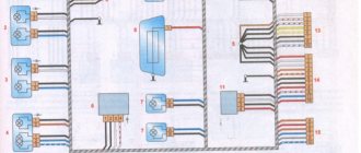
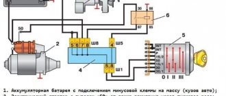
Block X1
1 To the engine management system controller 2 To terminal “87” of the ignition switch unloading relay 3 To the parking brake warning switch 4 To the brake fluid level sensor 5 Reserve 6 To terminal “50” of the ignition switch
Block X2
1 To ground terminal “-” 2 To rear window heating switch 3 To rear fog light relay 4 Reserved 5 Reserved 6 Reserved
Block X3
1 To terminal “I” of the fuel level sensor 2 To terminal “61” of the generator 3 To the ground terminal “-” 4 To terminal “87” of the ignition switch unloading relay 5 To the instrument lighting switch 6 To terminal “W” of the fuel level sensor 7 To the sensor temperature indicator 8 To oil pressure warning lamp sensor
Block X4
1 Reserve 2 To the ground terminal “-” 3 To the instrument lighting switch 4 To terminal “87” of the ignition switch unloading relay
Block X5
1 To the ground terminal “-” 2 To the instrument lighting switch 3 To the high beam headlight relay 4 To the exterior lighting switch 5 Reserve 6 To the turn signal relay
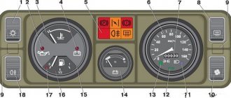
H1 - Instrument cluster lighting lamp H2 - Insufficient oil pressure warning lamp H3 - Fuel reserve warning lamp H4 - Battery charge warning lamp H5 - Parking brake warning lamp H6 - Engine control system warning lamp H7 - Rear fog lamp warning lamp H8 - Warning lamp malfunction of the service brakes H9 - Warning lamp for heated rear window H10 - Voltmeter illumination lamp H11 - Indicator lamp for turning on side lights H12 - Indicator lamp for turn indicators H13 - Indicator lamp for high beam headlights H14 - Speedometer illumination lamp P1 - Temperature indicator receiver P2 - Level indicator receiver gasoline P3 — Voltage indicator P4 — Speedometer VD1, VD2 — Diode X1, X2, X3, X4, X5 — Pin block
Read also: Low-bed trawl for transporting special equipment
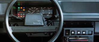
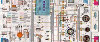
We present to your attention a diagram for connecting the dashboard of a VAZ-2105 and VAZ-2104 with a “fifth” dashboard. It can be useful not only when troubleshooting problems and breakdowns in the instruments on the panel, but also when installing the dashboard from the Volga GAZ-3110 on a classic. We hope it will be useful.
- — external lighting switch;
- — rear fog light switch;
- - dashboard;
- — block of warning lamps;
- — instrument cluster;
- - voltmeter;
- — speedometer;
- — rear window heating switch;
- — heater motor switch;
- — additional resistor for the heater electric motor;
- — heater electric motor;
- — block of the instrument panel harness to the instrument panel harness;
- — block of the instrument panel harness to the instrument panel harness;
- — instrument panel harness connector to the instrument panel harness.
A is the grounding point of the heater motor.
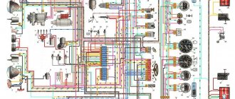
| 1 – oil pressure warning lamp sensor; 2 – coolant temperature indicator sensor; 3 – mounting block; 4 – ignition relay; | Read also: Pay for Platon by car number A detailed description of such a unit as the connection diagram of the VAZ 2105 Zhiguli instrument cluster has a good structure with thematic headings. In addition, there is always the opportunity to familiarize yourself with the intricacies of installation. There are often situations when a driver is confident in his abilities, but when he gets down to work, questions begin to arise. Thanks to our portal, such moments can be easily avoided. The site is a database that is updated regularly. By using it as a support during repair work, the car enthusiast receives a serious advantage. Each of the articles has reliable support, tested in practice. In addition to the repair manual, the owner of a personal car will be able to prevent a lot of breakdowns that occur due to the human factor, thanks to the information located on the site. Users are presented with a lot of useful recommendations for proper operation, which will help significantly extend the life of the unit and avoid many negative consequences. Online support is an excellent and most convenient way to obtain the necessary information. Another significant plus is that articles are written for people. We understand that the reader will do everything with his own hands, and we try to make it as convenient and efficient as possible. Use the resource at any time of the day and find the answer to any question you may have regarding cars. «> Add a comment Cancel reply
Monte Carlo versionŠkoda Popular Sport "Monte Carlo" 1936 Technical section |
Difficulties in repairing electrical equipment
The biggest problem that can arise during repair work on a VAZ-2105 is a mismatch in the color of the wiring with that indicated in the diagram.
If the car is many years old, then most likely the wiring has been replaced many times. The previous owner of the car was unlikely to be concerned that the wiring colors did not match the colors in the diagram. Most likely, if a car needed urgent repairs, the first wires that came to hand were installed on it. Therefore, a new car owner will have to face difficulties and figure out which wire is connected where. In this case, you can immediately make some adjustments for yourself in the future using felt-tip pens. During repairs, you can paint each wire in the desired color, this can save time for the next inspection or diagnosis. Another difficulty that a car owner may encounter when repairing a VAZ-2105 is partial replacement of the wiring. The previous owner could only replace part of the wires, thereby causing the current owner a lot of trouble. This situation causes even more confusion, and in this case it would make more sense to simply replace all the wiring.
The most common reason for a VAZ-2105 breakdown is damaged wire insulation or lack of contact. In this situation, it is necessary to test all sections of the wiring using a special device. The non-working electrical wiring is replaced with a new one, or part of the non-working wire can be replaced. If the insulation is damaged, then use electrical tape to eliminate this problem.
Possible faults
Dismantling and repair of the device may be required for the following malfunctions:
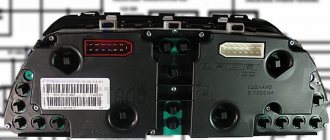
When repairing or replacing the instrument panel (instrument panel) of VAZ cars with a more modern and convenient version of VDO, made with LEDs, you will need connection diagrams and pinouts for the connectors. panels for this, the editors of 2SHEMI.RU have prepared a collection complete with pinouts of panel contacts for all popular models of this car.
The main symbols that are found on the dashboard of absolutely any car of the VAZ family are: speedometer, fuel gauge, tachometer and sensors to indicate engine temperature.
Installation and repair instructions
Dismantling the control panel may be required for repairs, tuning the panel, replacing sensors, etc. The procedure is simple and can be performed at home.
Tools and materials
To disassemble and repair the dashboard, you must prepare the following tools and materials:
- a set of keys;
- Screwdriver Set;
- diagnostic tester;
- new sensors and parts needed for replacement;
- elements for tuning.
It is better to buy originals to avoid fakes.
Algorithm of actions
To dismantle the tidy, you need to perform the following steps:
- Turn off the power supply to the machine by disconnecting the negative terminal from the battery.
- After unscrewing the mounting bolts, you need to remove the casing from the steering column.
- By removing the plugs and unscrewing two screws, the instrument panel is removed.
- Next, the wire plugs are disconnected.
- After opening the glove compartment, you need to unscrew the mounting bolts. The bolts securing the shelf for things are unscrewed in the same way.
- By pulling the handle of the hydraulic light corrector, you need to remove it. Then, using a socket wrench, unscrew the mounting nut and push it in.
- In the glove compartment, disconnect the power cord for the backlight lamp.
- After unscrewing the two bolts, you need to move the heater control unit.
- Next, you should dismantle the air duct.
- The next step is to unscrew all the console fasteners.
- When the last two fastening nuts in the center are unscrewed, you need to carefully remove the panel from the studs and remove it from the interior.
Next, the necessary repairs, tuning, replacement of sensors are performed, and backlighting is installed. After completing all the manipulations, the assembly of the device is carried out in the reverse order of disassembly.
To make assembly easier, during disassembly you should mark the wires and sort the devices and sensors.
Diagnosis of failure
How to properly check a car's electrical circuit:
- First, diagnose the circuit from the generator to the coil. Make sure that the contacts in this area are not oxidized; there may be breaks. If there is oxidation, then the contacts just need to be cleaned. Bad wires must be replaced.
- Check the functionality of the coil. You need to find out if there is spark. Take out one high-voltage wire and bring it to the metal. When you try to start the engine, a spark should jump between the cable contact and the metal. If it is not there, then it is necessary to more carefully diagnose the main components of the ignition system.
- Also diagnose the performance of the spark plugs and distributor. Sometimes the inability to start the engine is due to the formation of carbon deposits on the spark plugs; if this is the case, then the deposit must be removed. There can be many reasons for the appearance of soot; read more about them, as well as options for getting rid of it, here.
Sorry, there are no surveys available at this time.
What you will need:
- Leather substitute or leather, a piece of at least 2x2 meters.
- Hot melt adhesive or other suitable adhesive for leatherette and leather, for example, Kleiberit.
- Construction hairdryer.
- Brushes and knife.
Of course, covering a dashboard with genuine leather is very expensive, but it is resistant to mechanical damage and has a more presentable appearance than other materials. But you can also make tuning of the dashboard using artificial coatings. The main thing is to choose the right color and texture so that the car looks stylish and not like a gypsy car. The ideal option would be leatherette. It is easy to work with and has a fairly wide selection of colors.
Features of the electrical equipment of the VAZ 2105 car
The electrical equipment of the VAZ-2105 car is made according to the classic single-wire circuit for the Zhiguli family, in which:
- the metal body of the car plays the role of a second wire;
- the negative terminals of all electrical devices and components are connected to ground;
- electrical circuits are protected by fuses;
- the operation of the main systems is activated through the vehicle's ignition switch.
For reference: the ignition switch controls electrical networks by supplying power from the battery or generator. The contact group of the lock is designed in such a way that when the engine starts, the electrical wiring of the VAZ 2105 secondary circuits is turned off.
Egnition lock
The ignition switch was used as a control system for the vehicle's electrical systems, which had four main positions:
For reference: the factory instructions inform you that, regardless of the position of the key, the interior lighting lamps, brake light lamps (when the brake pedal is pressed), the horn and the connector for connecting a portable lamp remain energized.
Fuse and relay box
To protect electrical circuits and devices, a fuse circuit is used to break the electrical connection. This happens when the voltage increases - the fuse-link melts due to temperature and the circuit is disconnected.
The photo shows:
- From 1 to 17 – fuses;
- Relay 18 is responsible for turning on the low beam headlights;
- Relay 19 is responsible for turning on the high beam headlights;
- Relay 21 activates the headlight cleaner and washer;
- Relay 22 is responsible for turning on the heated rear window.
For reference: under No. 20 the jumper is indicated. The wiring diagram of the VAZ 21053 in the export version is distinguished by the installation of a relay for turning on sound signals in this place.
Headlight unit
The main and most noticeable difference from the classic Zhiguli models of the VAZ 2105 were the headlights. It was their massive appearance that gave the car a modern look. And the ability to remotely adjust the direction of the light beam was completely new.
For these purposes, several main and additional devices were used, among which a new product was the hydraulic headlight corrector.
His role was as follows:
- When the car was loaded, the rear part of the body lowered;
- The luminous flux of high and low beam headlights began to blind oncoming vehicles;
- With the help of a hydraulic corrector, the driver could lower (tilt) the headlights without leaving the car.
Thanks to this, the problem of driving safety in the dark was solved.
Historical reference
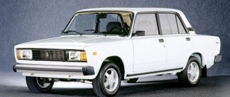
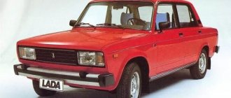
The VAZ 2101 platform was taken as the basis for production. At its core, it was the same rear-wheel drive five-seater sedan car. The VAZ 2105, with its design, practically copied the models of cars produced in Europe in the early 80s, and cost an order of magnitude lower, which predetermined its popularity in Western countries.
Abroad, the car was named Lada Riva and Lada Nova (depending on the country of sale). Under these names he was shown in video advertisements.
The car plant produced several modifications of the VAZ 2105:
- With the VAZ-2105 index, the car was equipped with a 4-speed gearbox. gearbox and 1290 cc carburetor engine. cm (63 hp);
- The VAZ-21050 was equipped with a 5-speed checkpoint;
- The VAZ-21051 was equipped with an engine from the VAZ 2101 (volume 1200 cc, power 58 hp) with a 4-speed. checkpoint;
- The VAZ-21053 was equipped with a VAZ-2103 carburetor engine (volume 1450 cc, power 71 hp);
- The VAZ-21053-20 was equipped with an injection engine from the VAZ-2104 (volume 1450 cc, power 71 hp), which met Euro-2 requirements. It also came with 5 tbsp. Transmission.
For reference: the electrical wiring of the VAZ 21053 was distinguished by a different form of terminals in the engine compartment. This was caused by the installation of an ECM - an electronic engine management system and additional sensors.
Installation of a tachometer from a VAZ 2106 on a VAZ 2105
At one time, having successfully equipped the dashboard of the VAZ 2103 with such an important device as a tachometer, the developers of subsequent VAZ modifications began a series of incomprehensible experiments, as a result of which the truly successful VAZ 2105 model was left without this convenient device. However, not all owners of the “five” are ready to put up with such a defect, especially since with some effort and skillful hands, the tachometer from the kit of the later VAZ 2106 can not only be successfully installed on the dashboard of the VAZ 2105 (at the location of the combination water-gasoline indicators and battery-oil lights), but will also fully perform its functions.
So, to complete the task you will need:
- “Beard” modification of the VAZ 2107. However, another one will do, the main thing is that it provides for the placement of instruments;
- A set of instruments from a VAZ 2106, namely indicators for oil, gasoline and water and, of course, the tachometer itself;
- Wires with a total length of 9m. In our case, it will be 1 m of white wire for the general minus, 1 m of red for the general positive, 1 m of green wire to connect the temperature sensor, one meter of yellow wire to provide general illumination, 1 m of pink wire for the gasoline sensor and three gray wires of 1 m each for connection emergency fuel reserve lamps, oil sensor and oil pressure (the oil pressure circuit is created by analogy with the VAZ 2106 and, if desired, can be abandoned);
- Connection block for 8 contacts assembled “male” and “female”;
- An additional oil pressure sensor and, accordingly, a tee for connecting it (again, to introduce a successful oil pressure alarm as on the “six”).
After all the necessary components are at hand, we carry out preliminary wiring of the wires going to the devices, gasoline, water, oil, for which we solder them together:
- White wires with a black stripe, intended for connecting the common negative (marked as “BN” on the device terminals);
- Red wires are common positive (labeled “C”);
- White backlight power wires (marked as “B” on devices).
- As a result, at the output of the instrument cluster we should receive one red “positive” wire, one white wire with a black stripe of a common “minus” and one white wire for connecting the backlight.
Next, we insert the three wires of the combined circuits we received into the contact block of the “male” version that we purchased (indicated by number 1 in the diagram). After that, we pack in the same part of the 8-pin block: