Site about electronics, technology and UNIX OS
12/24/2017 by admin | 0 comments
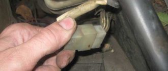
Along with the instrument panel, I did one more thing that had been planned for a long time, but I put it off just before replacing the instrument panel. This is a replacement for the interior heater switch button. I bought this button at the end of September, I really looked for it for a long time, but I still found it. It looks exactly the same as the original one, only the new one has 5 pins on the reverse side, instead of the three of the original one:
If someone decides to buy one for themselves, then its marking is “ 72.3709-02A ”. Also, in order not to deal with wires and terminals for connecting the backlight, I bought a block with eight wires connected for this button. I left only three wires in this block and removed the remaining terminals. On the remaining wires, I crimped the knife terminals on the reverse side so that they could be connected to the wires going to the heater motor. My heater wires are quite short, and it is very inconvenient to remove and put them on when removing the frame with the instrument panel. And most importantly, when installing the frame back, I had to figure out these three wires - which goes where, so that the button works correctly. Now, when you connect the block, everything will immediately be correct; you won’t be able to put it on the button incorrectly.
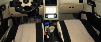
I decided to connect the backlight for the heater button to the glove box lighting. I crimped one wire with a special female/male terminal, and the second wire with a screw terminal. Thus, I secured the mass to the pin that secures the torpedo to the body, and connected the second wire to the light bulb in the glove box. I covered the often protruding knife terminals that go to the heater motor wires with heat shrink so that after assembly they would not shorten anything for me under the dashboard. Well, connecting the button itself after installing the frame with the tidy was quick and convenient:
Now all that remains is to tuck the button with the block inside into the frame of the instrument panel. After connecting and installing in place, all that remains is to check how the button will look and work.
Everything turned out just as I had planned. Now I have a desire to find and try to install an engine from a front-wheel drive VAZ in the stove, but again, I don’t want to buy a new engine, I will look for a used one in working condition and then experiment with it.
in short, one is clearly +, the other two are two speeds, one goes to the fan immediately, this is understandable, and the second is somewhere like in a relay that reduces the speed, now tell me which terminal I should put + in, and which 2 others
The idea is this, I don’t need a lower speed, so I use it for PTF (needless to say)
with one press, the PTF will work, and with the second press, the stove itself will work)
Stove malfunctions
Due to the simple design, there are not so many faults in the interior heating system of the VAZ-2107. They are divided into mechanical and electrical. Mechanical problems include:
- jamming of the antifreeze supply valve;
- radiator clogged;
- breaks in the drive mechanism cables;
- smudges.
The tap and heater radiator are the “weak” points in the VAZ-2107 stove. If in winter the tap works frequently, then with the onset of summer it turns off and remains in that position. Because of this, it jams, and when winter comes, attempts to open it lead to a break in the control cable.
Video: The heater on the classic VAZ 2101-07 does not work. We are looking for the reason.
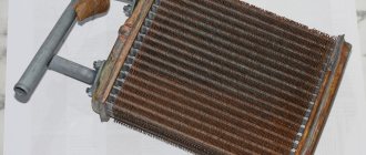
It is difficult to “move” a faucet that is stuck in one position, so it is easier to replace the faulty unit. And cutting off the antifreeze supply also affects the radiator. The absence of fluid movement for a long period (when operating a car in the summer, when the stove is not in use) leads to intensive formation of oxides inside the radiator, which clog the heat exchanger pipelines. Because of this, the throughput of the radiator decreases, and with it the performance of the stove.
A clogged heater radiator is washed, but if there are a lot of deposits, then they can only be removed mechanically, and for this the radiator is unsoldered. Soldering it back is difficult and sometimes it is easier to replace the heat exchanger than to wash it.
Leaks are also a common failure. They occur at the junction of the pipes, and also if a crack appears in the radiator. In the first case, the leak is eliminated by tightening the fastening clamps, in the second - by soldering or replacing the radiator.
Electrical faults include burnout of the electric motor, open circuit of its power supply and breakdown of the control key.
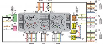
Electrical diagram VAZ-2107 carburetor
Electrical diagram of VAZ 2107, 21074 produced in 1988-2001 with generator 37.3701
- block headlights
- side direction indicators
- accumulator battery
- starter relay
- carburetor electro-pneumatic valve
- carburetor microswitch
- generator 37.3701
- gearmotors for headlight cleaners *
- Fan motor switch sensor
- engine cooling fan motor
- sound signals
- distributor
- spark plug
- starter
- coolant temperature gauge sensor
- engine compartment lamp
- low oil pressure warning sensor
- low brake fluid level indicator sensor
- windshield wiper motor
- carburetor electro-pneumatic valve control unit
- ignition coil
- headlight washer pump motor *
- windshield washer pump motor
- mounting block
- windshield wiper relay
- hazard warning and direction indicator relay
- brake light switch
- reverse light switch
- ignition relay
- ignition switch
- three lever switch
- hazard switch
- socket for portable lamp**
- heater fan switch
- additional resistor for the electric motor of the heater (stove)
- rear window heating indicator lamp
- low brake fluid level warning lamp
- signaling unit
- heater fan electric motor
- glove compartment lamp
- light switches on the front door pillars
- switches for warning lights of open front doors ***
- front door open warning lights ***
- connection block
- cigarette lighter
- watch
- instrument light switch
- diode for checking the serviceability of the low brake fluid level indicator lamp
- fuel level indicator
- fuel reserve indicator lamp
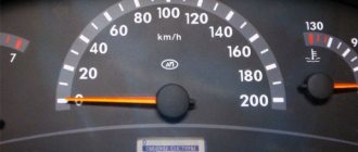
- speedometer
- turn signal indicator lamp
- carburetor choke indicator lamp
- battery charge indicator lamp
- carburetor choke warning switch
- instrument cluster
- econometrician
- light switches on the rear door pillars
- coolant temperature gauge
- tachometer
- parking brake indicator lamp ("handbrake")
- low oil pressure warning lamp
- high beam indicator lamp
- indicator lamp for turning on external lighting
- voltmeter
- parking brake indicator switch ("handbrake")
- outdoor light switch
- rear window heating switch with backlight
- rear fog light switch with on/off indicator *
- fog light circuit fuse
- lampshade ****
- tail lights
- level indicator and fuel reserve sensor
- connectors for connecting to the rear window heating element *
- license plate lights 2107
Wiring diagram VAZ-2107 carburetor - full view:
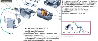
Principle of operation
The heating system works simply - to ensure air heating, the driver uses the upper slider to open the antifreeze supply valve to the heater radiator. If the air supply damper is open (the middle slider is in the extreme right position), then the air flow through the box that separates the moisture and the damper enters the stove body. Passing through the radiator, the air heats up, and then moves depending on the location of the remaining dampers.
If the lower slider is moved to the right, then the heated air will go to the windshield area, and if it is positioned to the left, it will go to the center of the cabin and to the side windows. To supply heated air to the feet, the driver needs to lower the lower damper lever down.
When driving at high speeds, the air flow through the air intakes moves intensively, so it is not necessary to turn on the fan. But if the movement speed is not enough, the fan creates forced circulation.
Using dampers and a fan, the driver controls the stove - sets the speed of air movement, the degree of its heating and the area of distribution.
Mounting block connection diagram
P1 — relay for turning on the heated rear window; P2 - relay for turning on the headlight cleaners and washer; P3 - relay for turning on sound signals; P4 - relay for switching on the electric motor of the engine cooling system fan; P5 - headlight high beam relay; P6 - low beam headlight relay; A - the order of conditional numbering of plugs in the mounting block blocks. The outer number with the letter “Ш” in the plug designation is the block number, and the inner number is the conventional number of the plug.
Let's sum it up
Timely diagnostics, preventive cleaning and inspection of elements of the vehicle’s heating system is a guarantee of high-quality operation of the stove. Experts recommend checking the heating system on the VAZ-2107 at least twice a year - in autumn and spring. Any driver can handle preventive cleaning and adjustments of the stove on his own; to do this, you just need to understand the structure of the heating and ventilation system of the cabin and the principle of its operation. The easiest way to do this is to always have a visual instruction manual for your car nearby.
Don’t put off any further work to improve the functioning of your car’s heating system. Proper care will ensure uninterrupted operation of the heater and a comfortable temperature in the interior at any time of the year.
Schemes of individual blocks of the seven
Power supply system
Power plant starting system
1 - starter; 2 - relay; 3 — ignition switch; 4 - battery
Ignition system
1 - generator; 2 — ignition switch; 3 - distributor; 4 - breaker; 5 — candles; 6 - coil; 7 - battery
Contactless ignition system
External and internal lighting
Windshield wipers and washers
1 — electric motors of the windshield wiper; 2 — washer motor; 3 — mounting block; 4 — ignition switch; 5 - washer switch
Cooling Fan
1 — fan electric motor; 2 - sensor; 3 — mounting block; 4 - ignition relay; 5 - ignition switch.
Comments
2 coolers
if you install two 40*40 coolers, it will be even better, you don’t even need to cut anything
- Login to leave comments
Main Cooler (fan)
The main thing is to put the cooler (fan) in the correct blowing position, otherwise it will force air back into the stove)
- Login to leave comments
I've been wanting to make it like this for a long time
I've been wanting to refine it using this method for a long time, but never got around to it. finally got it together. I advise you to install coolers on both side deflectors. and in summer the extra movement of air along the side will not hurt, and they work absolutely silently!
- Login to leave comments
Subjec
To say the least.
- Login to leave comments
A comment
- Login to leave comments
Vacuum cleaner
Well, I don’t know, I don’t know, on computers they don’t hesitate for a long time and, like vacuum cleaners, they collect all the dust.
- Login to leave comments
modification of the stove
Fans of this type are complete garbage, because: 1. They are not designed to blow hot air through themselves - very quickly the electronics inside will die from overheating. 2. There is no lubrication there, as well as the bearing (or rather the lack of it), in a month it will all come out and the cooler will begin to hum when starting “cold”, then it usually jams and the electronics burn out. 3. Dust collects perfectly on its blades, and accordingly, when the car is damp, hello fungi
vote
Article rating
Wires for connecting electrical appliances
| Connection type | Section, mm 2 | Insulation color |
| Negative terminal of the battery - vehicle ground (body, engine) | 16 | Black |
| Starter positive terminal - battery | 16 | Red |
| Positive contact of the generator - plus battery | 6 | Black |
| Generator - black connector | 6 | Black |
| Terminal on the generator “30” – white MB block | 4 | Pink |
| Starter connector “50” – starter relay | 4 | Red |
| Starter Start Relay - Black Connector | 4 | Brown |
| Ignition switch relay - black connector | 4 | Blue |
| Ignition switch output “50” – blue connector | 4 | Red |
| Ignition switch connector “30” – green connector | 4 | Pink |
| Right headlight plug - ground | 2,5 | Black |
| Left headlight plug - blue connector | 2,5 | Green, gray |
| Generator output “15” – yellow connector | 2,5 | Orange |
| Right headlight connector - ground | 2,5 | Black |
| Left headlight connector - white connector | 2,5 | Green |
| Radiator fan - ground | 2,5 | Black |
| Radiator Fan - Red Connector | 2,5 | Blue |
| Ignition switch output “30/1” – ignition switch relay | 2,5 | Brown |
| Ignition switch contact “15” – single-pin connector | 2,5 | Blue |
| Right headlight - black connector | 2,5 | Grey |
| Ignition switch connector “INT” – black connector | 2,5 | Black |
| Six-pin block of the steering column switch - “ground” | 2,5 | Black |
| Two-pin block of the steering column switch - glove box illumination lamp | 1,5 | Black |
| Glove compartment light - cigarette lighter | 1,5 | Black |
| Cigarette lighter - blue block connector | 1,5 | Blue, red |
| Rear window defroster - white connector | 1,5 | Grey |
Car wiring diagram
1 – radiator fan drive motor; 2 – relay and fuse block (mounting block); idle speed sensor; 4 – engine control unit; 5 – potentiometer; 6 – set of spark plugs; 7 – ignition control unit; 8 – electronic crankshaft sensor; 9 – electric fuel pump; 10 – tachometer 2107; 11 – lamp for monitoring the health of electronic systems; 12 – ignition system control relay; 13 – speed sensor; 14 – diagnostic connector; 15 – set of injectors; 16 – adsorber solenoid valve; 17, 18, 19 – fuse block protecting the injection system circuits; 21 – electronic fuel pump control relay; 22 – electronic relay for controlling the intake pipe heating system; 23 – intake pipe heating system; 24 – fuse protecting the heater circuit; 25 – electronic oxygen level sensor; 26 – cooling system temperature control sensor; 27 – electronic air damper sensor; 28 – air temperature sensor; 29 – pressure control sensor.
Fuse and relay diagram 2107
On newer “sevens” a block with 17 fuses and 6 relays is installed. VAZ 2107 fuses on the “new” unit protect the following electrical circuits and devices:
- Reversing lamps, heater fan, rear window defroster warning lamp and relay, rear wiper motor and rear washer pump.
- Electric motor for front wipers.
- Reserve socket.
- Reserve socket.
- Power supply for heated rear window.
- Clock, cigarette lighter, power socket “carrying”.
- Signal and radiator fan.
- Turn signal lamps in emergency mode.
- “Fog lights” and a relay that regulates the voltage of the on-board network.
- Instrument panel lamps.
- Brake light bulbs.
- Right high beam headlight.
- Left high beam headlight, high beam warning lamp.
- Side lights (rear right, front left), license plate and engine compartment lighting.
- Side lights (rear left, front right), glove compartment and cigarette lighter lamps.
- Low beam (right lamp).
- Low beam (left lamp).
The block relays perform the following functions:
- Heated rear window relay.
- Headlight cleaner and washer relay.
- Signal relay.
- Cooling system electric fan relay.
- High beam relay.
- Low beam relay.
The fuse block of the VAZ 2107 (injector) is no different from the block on the carburetor “seven”. Injection models are simply equipped with an additional relay and fuse box installed in the cabin under the glove compartment. The block includes three relays - the “main” relay, the fuel pump relay and the fan relay.
Stove modernization
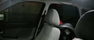
Very often, in parallel with the prevention of stove malfunctions and its settings, the driver modernizes the heating system for more efficient operation.
Most often, for these purposes, the standard fan and resistor are replaced with products from the figure eight. The new fan is larger in size, due to which a larger amount of warm air is supplied, and the vehicle interior warms up faster. The new fan fits into the standard seat with virtually no modifications.
Sometimes, for better airflow of the driver’s side windows, additional small fans are installed in the deflectors. Such improvements, combined with preventive maintenance, will ensure comfort and warmth in the cabin even in the coldest times.