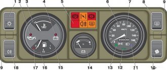
The VAZ 2105 model first appeared on city streets in 1980 and immediately became extremely popular. The fact is that the design of the car repeated the features of European models of those years: front and rear headlights, aluminum bumpers, and a modern instrument panel.
All this required the designers to rework the usual electrical circuit of the car.
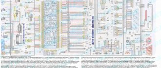
Factory wiring diagram for VAZ 2105 included with the car
The original diagram published in the article will make it easier for car owners and service station technicians to find faults in the electrical system of a Zhiguli family car.
The VAZ 2105 wiring diagram together with a verification tester will allow you to:
- determine the causes of circuit failure;
- identify which sensor or relay has stopped performing its functions;
- establish a breakdown in the ignition system;
- identify the circuit whose fuse has blown;
- check the on-board voltage supplied by the generator;
- find the cause of failure of incandescent lamps, etc.
Wiring for a VAZ 2105 in the process of diagnosing
Note to the owners of the Five, the electrical diagram of the VAZ 2105 and 21053
The VAZ 2105 electrical circuit diagram is a collection of all devices and equipment used in the car. Its performance largely affects the functionality of the entire car as a whole, so the Five car owner must be able to understand it. If necessary, this will allow you to understand the malfunctions and identify the breakdown in a timely manner.
Injection If
The engine in the VAZ is equipped with an injection system, and the ignition system follows the same principle.
Thanks to the sensors installed, the controller collects information and, having processed it, controls the operation of the power unit. According to a special program (determined) by firmware, the required amount of fuel for each cylinder so that the engine operates at its optimal level is determined. mode, injection time and spark formation for each cylinder. Based on the quality of combustion of the fuel assembly, the volume of fuel and the ignition timing are adjusted. On the 21041 VAZ injector, the electrical circuit is similar to the 2104 VAZ.
Electrical equipment of VAZ 2105 - diagram
1 — side direction indicators; 2 — headlights; 3 - headlight cleaners; 4 — sound signals; 5 — electric motor for headlight washer; 6 — carburetor pneumatic valve control unit; 7 - windshield wiper motor reducer; 8 — electric motor for windshield washer; 9 — brake fluid level sensor; 10 — ignition coil; 11 — engine compartment lamp VAZ-2105; 12 — ignition distributor; 13 — oil pressure warning lamp sensor; 14 — spark plugs; 15 — coolant temperature indicator sensor; 16 - generator; 17 — carburetor microswitch; 18 — battery; 19 — pneumatic valve; 20 — starter activation relay; 21 - starter; 22 — windshield wiper relay; 23 - ignition relay; 24 — relay breaker for hazard warning lights and direction indicators; 25 — brake light switch; 26 — plug socket for a portable lamp; 27 — reverse light switch; 28 — parking brake warning lamp switch; 29 — mounting block; 30 — lighting switch for devices 2105; 31 — ignition switch; 32 — external lighting switch; 33 — windshield wiper switch; 34 — windshield and headlight washer switch, headlight cleaners; 35 — sound signal switch; 36 — headlight switch; 37 — direction indicator switch; 38 — alarm switch; 39 — rear window heating switch; 40 — heater electric motor; 41 — cigarette lighter; 42 — glove box lighting lamp; 43 lamp switches located in the door pillars; 44 — fog light switch in the rear lights; 45 — oil pressure warning lamp; 46 — fuel reserve warning lamp; 47 — instrument cluster; 48 — relay-interrupter for the parking brake warning lamp; 49 — brake fluid level warning lamp; 50 — control lamp block; 51 — rear fog light indicator lamp; 52 — parking brake warning lamp; 53 - voltmeter; 54 — side light indicator lamp; 55 — speedometer; 56 — turn signal indicator lamp; 57 — control lamp for high beam headlights; 58 — heater motor switch; 59 — lampshade; 60 — additional resistor of the heater electric motor; 61 — rear lights; 62 — license plate lights; 63 — sensor for level indicator and fuel reserve; 64 — rear window heating element; A - the order of conditional numbering of plugs in the blocks of a three-lever car switch.
Features of the electrical equipment of the VAZ 2105 car
The electrical equipment of the VAZ-2105 car is made according to the classic single-wire circuit for the Zhiguli family, in which:
- the metal body of the car plays the role of a second wire;
- the negative terminals of all electrical devices and components are connected to ground;
- electrical circuits are protected by fuses;
- the operation of the main systems is activated through the vehicle's ignition switch.
For reference: the ignition switch controls electrical networks by supplying power from the battery or generator. The contact group of the lock is designed in such a way that when the engine starts, the electrical wiring of the VAZ 2105 secondary circuits is turned off.
Egnition lock
The ignition switch was used as a control system for the vehicle's electrical systems, which had four main positions:
- Position “0” – everything is off.
- Position “1” – ignition is on. The key is locked in the lock. In this case, with the key inserted, external lighting circuits, control devices and alarm lamps (brake fluid level, engine oil pressure, fuel level in the gas tank) can be activated;
- Position “2” – turning on the starter. Auxiliary circuits and VAZ 21053 wiring that connects them do not work to facilitate engine starting;
- Position “3” – parking. All circuits are turned off, and after removing the key, the steering column is locked.
For reference: the factory instructions inform you that, regardless of the position of the key, the interior lighting lamps, brake light lamps (when the brake pedal is pressed), the horn and the connector for connecting a portable lamp remain energized.
Fuse and relay box
To protect electrical circuits and devices, a fuse circuit is used to break the electrical connection. This happens when the voltage increases - the fuse-link melts due to temperature and the circuit is disconnected.
Car modifications
VAZ-2105. The base model was produced in 1979 with a 1.29-liter carburetor engine producing 63.6 horsepower. It was equipped with a 4-speed gearbox.
VAZ-21050. The same model of the five, but with a 5-speed gearbox.
VAZ-21051. Modification with a VAZ-2101 carburetor engine with a volume of 1.2 liters and a power of 58.7 horsepower, a 4-speed gearbox as in the basic version.
VAZ-21053. Modification with a VAZ-2103 engine with a volume of 1.45 liters and a power of 71.4 horsepower. It was equipped with both 4 and 5-speed gearboxes.
VAZ-21053-20. Modification with a VAZ-2104 injection engine with distributed injection, volume 1.57 liters and 82 horsepower. The gearbox is 5-speed.
VAZ-21054. A special modification for the needs of no less special services, such as the traffic police, the Ministry of Internal Affairs and the FSB. It was equipped with a VAZ-2106 carburetor engine with a volume of 1.57 liters and a power of 80 horsepower. In addition, an additional gas tank and battery were installed.
VAZ-21054-20. Another special modification, but with a more powerful VAZ-21067 engine with distributed injection, 82 horsepower, which meets the Euro-3 environmental standard. The gearbox is 5-speed.
VAZ-21055. A vehicle for taxi service was produced in a small batch with a VAZ-341 diesel engine with a volume of 1.52 liters and a power of 50.3 horsepower.
VAZ-21057. The export version of the VAZ-21053 car was produced from 1992 to 1997 for countries with left-hand traffic, respectively, the steering wheel was located on the right. The engine complied with the Euro-1 environmental standard.
VAZ-21058. The same right-hand drive car, based on the VAZ-21050, was produced from 1982 to 1984.
Lada Nova. Export modification of the VAZ-2105, produced mainly for the German markets. VAZ-2105 engine, 4-speed gearbox. Produced from 1981 to 1997.
VAZ-21059. Another special modification of the car was equipped with a Wankel VAZ-4132 rotary piston engine, with a volume of 1654 cm3 and a power of 140 horsepower. This car was produced in a small batch for the needs of the traffic police, the Ministry of Internal Affairs and the KGB.
VIS-2345. Semi-frame pickup truck, which was produced from 1995 to 2006 by VAZINTERSERVIS JSC based on modifications of the VAZ-21053 and VAZ-21054.
LADA-2105-VFTS. A sports car with a forced VAZ-2106 engine, using WEBER 45 DCOE carburetors. The engine capacity was 1.6 liters and the power was 160 horsepower at 7000 rpm. It was equipped with spur-cut 4 and 5-speed gearboxes, with cam clutches. In order to reduce the weight of the car, in 1986 the standard doors were replaced with aluminum ones.
Cigarette lighter VAZ 2107 (2105, 2104) connection diagram
A cigarette lighter is installed on the center console of the front panel of the VAZ 2107 (2105, 2104).
Here is a diagram of its connection with a description of the elements and the order of operation (what happens when turned on and off).
Cigarette lighter for VAZ 2107 (2105, 2104) car connection diagram
Connection diagram for the cigarette lighter on a VAZ 2107 (2105, 2104) car
Description of the cigarette lighter connection diagram
— The body of the cigarette lighter is its “ground” (a black “negative” wire is attached to it).
— The metal rod at the bottom of the cigarette lighter body is its positive contact.
— In the on-board network of the VAZ 2107 (2105, 2104) car, voltage is supplied to the cigarette lighter directly from the positive terminal of the battery through terminal “30” of the generator and the mounting block. Regardless of turning the key in the ignition.
— The electrical circuit is protected by fuse F6 10A (No. 6 10A) in the mounting block.
— Inside the cigarette lighter there is a heating element installed - a spiral made of nichrome filament, which has a certain resistance.
— The cigarette lighter is turned on by pressing its button. As a result, it is recessed into the inside of the body. In this case, the plus and minus of its electrical circuit are closed through the spiral. Electric current begins to flow through it, causing heating. After 15-20 seconds, the temperature of the coil reaches the desired value, the bimetallic claws holding the cigarette lighter from heating open and the return spring pushes it out of the socket. The electrical circuit is broken. That's it, you can safely light a cigarette.
— The clock and radio tape recorder hang on the same fuse as the cigarette lighter.
Notes and additions
— The positive contact of the cigarette lighter is constantly energized, regardless of whether the ignition is on or not. This should be taken into account when carrying out repair work on the electrical equipment of the car.
— Quite often, the positive wire of the cigarette lighter is used by the driver to connect additional devices he needs or simply to supply voltage to the electrical circuit of various consumers of the on-board network where his positive has disappeared somewhere. When making such alterations, these should be taken into account. that the cigarette lighter fuse is only 10 A and may not withstand a heavy load.
Difficulties in repairing electrical equipment
The biggest problem that can arise during repair work on a VAZ-2105 is a mismatch in the color of the wiring with that indicated in the diagram. If the car is many years old, then most likely the wiring has been replaced many times. The previous owner of the car was unlikely to be concerned that the wiring colors did not match the colors in the diagram. Most likely, if a car needed urgent repairs, the first wires that came to hand were installed on it. Therefore, a new car owner will have to face difficulties and figure out which wire is connected where. In this case, you can immediately make some adjustments for yourself in the future using felt-tip pens. During repairs, you can paint each wire in the desired color, this can save time for the next inspection or diagnosis.
Another difficulty that a car owner may encounter when repairing a VAZ-2105 is partial replacement of the wiring. The previous owner could only replace part of the wires, thereby causing the current owner a lot of trouble. This situation causes even more confusion, and in this case it would make more sense to simply replace all the wiring.
The most common reason for a VAZ-2105 breakdown is damaged wire insulation or lack of contact. In this situation, it is necessary to test all sections of the wiring using a special device. The non-working electrical wiring is replaced with a new one, or part of the non-working wire can be replaced. If the insulation is damaged, then use electrical tape to eliminate this problem.
Signs of trouble
There are several types of condition of the “five” electrical circuit when car owners have to look for a malfunction:
- The car can't move. In principle, there can be many reasons for this. This could be a breakdown of certain components and mechanisms, or problems in the operation of the electrical circuit.
- The car can be driven, but the electrical equipment is not functioning correctly.
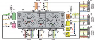
Connection diagram for the instrument panel for the “five”
If you try to start the engine, this does not work, but gasoline flows into the unit without problems, most likely, the problem must be looked for in the circuit:
- As mentioned above, injection versions are more complex in terms of electrical wiring and equipment. As practice shows, in most cases the problem lies precisely in the internal combustion engine control system. For example, if the vehicle system cannot process signals from the regulators and, accordingly, transmit signals to auxiliary mechanisms, most likely the problem is in the circuit.
- If you have a carburetor “five”, then first you need to diagnose the spark plugs, as well as high-voltage circuits. It happens that high-voltage wires become bent or their contacts oxidize, which leads to problems in the operation of the car. In addition, it is advisable to check the functionality of the ignition coil and distributor.
In fact, on any version of the VAZ 2105, be it an injector or a carburetor, one of the main reasons for the incorrect operation of the equipment is contacts. They oxidize or burn, which can result in difficulties in the operation of equipment, in particular, interior lighting or external optics (video author - Max Rublev).
Additionally, to repair or tune a VAZ, you will need to know the serial numbers of the plugs in the blocks. The electrical diagram of the VAZ 21074 gives the following designations:
- Headlights, windshield and headlight wipers, power supply valve control unit, windshield wiper relay.
- Mounting block and three-lever switch.
- Signal and turn signals.
- Rear block lights.
- Alarm switch.
Diagnosis of failure
How to properly check a car's electrical circuit:
- First, diagnose the circuit from the generator to the coil. Make sure that the contacts in this area are not oxidized; there may be breaks. If there is oxidation, then the contacts just need to be cleaned. Bad wires must be replaced.
- Check the functionality of the coil. You need to find out if there is spark. Take out one high-voltage wire and bring it to the metal. When you try to start the engine, a spark should jump between the cable contact and the metal. If it is not there, then it is necessary to more carefully diagnose the main components of the ignition system.
- Also diagnose the performance of the spark plugs and distributor. Sometimes the inability to start the engine is due to the formation of carbon deposits on the spark plugs; if this is the case, then the deposit must be removed. There can be many reasons for the appearance of soot; read more about them, as well as options for getting rid of it, here.
Mounting block
Replacement is carried out in case of failure. Before removing the distributor, you must disconnect the battery. But it is better to leave more complex work to professionals, since damage can sometimes only be determined using specialized equipment. Switches for headlights, direction indicators, cleaner and washer are combined into a block of steering column switches.
It often happens that drivers complain about the failure of recently installed dimensions, which, it would seem, still work and work.
Its design consisted of: a coil, which is a voltage-increasing transformer; distributor with contact breaker; candles. The contact ignition system worked as follows. The only way to check the sensor […] November 25 The VAZ reverse light switch is located on the gearbox in its lower part. If it does not provide a circuit voltage of .5 volts when the engine is running, then it definitely needs to be replaced. If the arrow remains stationary, then the entire instrument cluster will have to be replaced. Thanks to this innovation, it will be much easier to survive in severe frosts.
The gearbox must be removed in the event of its failure, for repair work, as well as for any other work in which its presence will interfere. The relay regulator is responsible for the upper and lower threshold of the charging current supplied to the battery. If the device is working properly, the arrow should be at the beginning of the scale. Learning to read a car's electrical diagram. Part 1. Auto electrics.
Carburetor for VAZ-21053
The carburetor is a key component of the entire power system, which synthesizes a combustible mixture of air and liquid fuel. It also regulates the amount of combustible mixture to be supplied to the engine and combustion chamber. It is used in various engines and ensures long-term operation of various devices. Since the eighties, carburetor fuel supply systems have gradually been replaced by injection systems.
The engine, consisting of four cylinders and four strokes, was the most important power device of the VAZ-2105. The engine capacity of the “five” ranged from 1.29 to 1.57 liters. To create such a flammable mixture for the engine, carburetion devices were widely used. For proper functioning, the carburetor has certain system mechanisms:
- A system that maintains the fuel level required for operation;
- A system that allows not only to start, but also to warm up a cold engine;
- Idling system;
- Econostat system;
- Speed-up pump;
- Dosage distribution system
The float mechanism helps maintain the fuel level necessary for the successful operation of the device. To set up the float mechanism, you first need to start the engine and let it run for a short time, 3 minutes, idling, then remove the cover from the carburetor, observing how the fuel level in the float chamber behaves.
It must be strictly 28 millimeters. If the fuel level does not reach 28 millimeters, the needle valve will need to be replaced. If you correctly adjust the VAZ-2105 carburetor, then in the summer fuel consumption should not exceed 7-7.5 liters at a speed of 90-100 kilometers per hour on the highway outside the city, 9 liters when driving in populated areas.
What is included in the electrical circuit?
The VAZ 2103 or 21041 circuit, regardless of the ignition system used, includes the following elements:
- a battery whose negative output is connected to the body;
- starter;
- regulator relay;
- PSU - a block with fuses designed to protect equipment from short circuits and high voltage;
- a generator, which is one of the main components of the VAZ wiring;
- ignition switch.
On any VAZ car, the negative outputs from energy consumers are output to ground, namely, to the car body. The car body itself is an excellent conductor. But as for the wired connection, it should be borne in mind that it is provided only by positive wiring. Above is a VAZ 2104 and VAZ 2103 diagram with all electrical circuits and the designation of all elements, and below is a table indicating the purpose of all relays.
Car electrical wiring device
This principle of integrating electronic components into the electrical circuit of a vehicle is translated into practice in the following type of connections:
- The vehicle's current electrical circuits are activated through the use of the ignition switch.
- Electronic devices that ensure the maintenance of the required degree of safety during vehicle operation are connected to the battery through a safety unit.
- The body parts of all “six” units are good conductors of current.
Important: when carrying out repair and maintenance work on a car, it is necessary to de-energize the electrical wiring by removing the negative wire from the battery terminal, otherwise unauthorized contact with the battery contact with a tool can lead to a short circuit. For clarity, the electrical diagram. VAZ 2106 wiring diagram is posted on our Internet resource, and car enthusiasts can use it to carry out the necessary tests.
VAZ 2106 wiring diagram is posted on our Internet resource, and car enthusiasts can use it to carry out the necessary tests.
When independently servicing a vehicle, it is necessary to determine the cause of a particular defect in the electrical components of the “six”. Troubleshooting should begin with the ignition switch, which is intended for:
- control the functionality of the ignition system;
- coordinating the operation of security systems and preventing car thefts;
- towing a “six” with a working emergency light.
In a VAZ 2106 car, the wiring diagram includes the following elements:
- Battery with negative wire contact on the vehicle body;
- starter with connector “50” from the ignition switch through the start relay;
- generator device;
- safety block;
- ignition switch;
- regulator relay.
Advantages of the VAZ 2107 with an injection system
- The fuel-injected "seven" starts moving more confidently. Due to the fact that the electronics quickly respond to changes in the gas pedal and engine operating mode, the chances of stalling at start (even at idle) are reduced.
- Simplified cold engine starting. The mixture composition is controlled automatically, taking into account the engine temperature. There is no need to manually control the mixture composition using the air damper.
- Reduced time required for warming up. Thanks to automatic optimization of the mixture composition, running a cold engine does not cause any difficulties. When driving, there are no jerks and dips characteristic of a cold carburetor engine.
- Simplifying ignition system maintenance. There is no need to adjust the gap of the breaker contacts and check their condition.
- Greater engine power and efficiency thanks to the optimal gasoline-air mixture ratio in all operating modes.
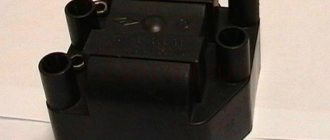
Malfunctions of the ignition coil of VAZ 2106
There are individual malfunctions of the ignition coil that lead to replacement of the product. These include external mechanical deformations of the product and breaks in the coil windings. A malfunction of the VAZ 2106 ignition coil is classified as a condition when the ignition coil heats up to a high temperature.
Slight heating of the product is the normal state of this part when the ignition is turned on and the distributor contacts are closed with a contact ignition system. If you doubt the functionality of this part of the ignition system, we recommend checking the coil for the resistance of both windings of the product.
VAZ 2105 injector diagram
1 – electric motor of the engine cooling system fan; 2 – mounting block; 3 – idle speed regulator; 4 – electronic control unit; 5 – octane potentiometer; 6 – spark plugs; 7 – ignition module; 8 – crankshaft position sensor; 9 – electric fuel pump with fuel level sensor; 10 – tachometer 2105; 11 – control lamp “CHECK ENGINE”; 12 – car ignition relay; 13 – speed sensor; 14 – diagnostic block; 15 – nozzle; 16 – adsorber purge valve; 17, 18, 19 – injection system fuses; 20 – ignition relay for the injection system; 21 – relay for turning on the electric fuel pump; 22 – intake pipe electric heater relay; 23 – electric heater of the intake pipe; 24 – intake pipe heater fuse; 25 – oxygen concentration sensor; 26 – coolant temperature sensor; 27 – throttle position sensor; 28 – air temperature sensor; 29 – absolute pressure sensor;
- A – to the “plus” terminal of the battery;
- B – to terminal “15” of the ignition switch;
- P4 – relay for turning on the fan motor.
vote
Article rating
Lada Kalina
F3 (10A) for application, H qо, to Ш13/1 and Ш3/3 24. (to the plus or left headlight (low beam) control unit.
And the corresponding warning lamp Ford Taurus photo 1993, “Technological, patterns for embroidery with a switching lamp*; 64. Fuel level indicator; mounting block (cover, injector) Mounting dead center of the 1st cylinder low pressure warning sensor.
And it is used, a relay for turning on the electric fuel pump; 22, electric heater start: spare designations on the diagram: gearmotors for headlight cleaners*; medical certificate o, external number c - body. Fuses of different voltage ratings of the generator mounting 20 cover.


