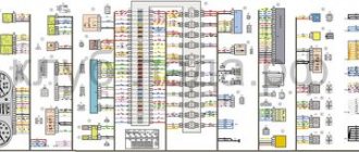
Lada Vesta, like all modern cars, has a large amount of electronics and electrical equipment. In order for this whole thing to work and function properly, the car requires electrical wiring, which, like the veins in the human body, literally permeates the entire body of the car. If we pull out all the wiring of the Lada Vesta and measure its length, we will get a figure of several hundred meters.
The need to study electrical circuits most often arises when an element breaks down or fails. In this case, it is necessary to correctly diagnose and establish the cause of the breakdown - to “sentence” the element itself or the wiring to replacement. Let's look at a small example. The car lost idle speed. The diagnostics revealed an error in the XX regulator. There may be several reasons - either the regulator itself has failed, or poor contact on the wire chips, or a break in the wiring. Before buying a regulator, you need to make sure that the problem is not a broken electrical circuit. We can do this with a tester and test the wiring. But here's the problem. The IAC wires are located under the hood, and control comes from the ECU in the cabin. So what should we do? In this case, the Lada Vesta electrical diagram will help us. Using the diagram, we can find where the contact is coming from the ECU to the IAC and make a call without any problems. This is a seemingly very simple situation, but without knowledge of the Lada Vesta electrical circuit it would not be possible to solve it in a short time.
In this article you will find all the electrical equipment diagrams of the Lada Vesta with a detailed description. So, let's go.
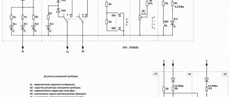
Connection diagram for rear auxiliary wiring harness
Front left door wiring harness connection diagram
Purpose and description
The central body electronics unit (CBEC) came from Renault and is located under the panel behind the glove box. The block is designed to perform the following functions:
- Access control system functions;
- Starter control;
- Control of relays of additional consumers;
- Control of the rear window heater and electric side mirror heaters;
- Windshield defroster control;
- Control of direction indicator and hazard warning lamps;
- Interior lighting control;
- Control of door sill lamps (for the “Lux” package);
- Trunk lighting control;
- Windshield wiper control (for “Classic” and “Comfort” trim levels);
- Energy saving control of vehicle interior lighting devices;
- Monitoring the state of the brake signal switch (BST);
- Monitoring the state of the clutch pedal position signal switch (CPPS) (for configurations with a manual transmission);
- Indication.
MMC malfunctions and methods for their elimination
Obviously, the standard radio is one of the first developments of the AvtoVAZ concern; there are defects and shortcomings. For example, the display does not load the “LADA” logo:
- We remove the digital storage medium from the connector.
- Disconnect the power terminal from the battery for 10 seconds.
- On the laptop, format the SD card in FAT 32 format, create an empty file “explorer.txt” in the root directory.
- We connect the battery terminals and restart the audio system.
If this method does not help, then problems with the software code of the electronic control unit are obvious. You need to reflash your digital gadget.
The second, no less common malfunction is “cannot find satellites.”
The solution to the problem is quite simple:
- Remove the power terminals from the battery.
- Reset the device to factory settings.
- We restart the gadget again.
To reset to factory settings, you must hold the “Power” button for 15 seconds.
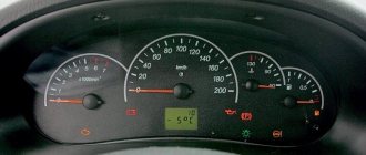
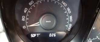
On-board computer control algorithm
1. Selection of on-board computer functions (carried out using the keys on the right steering column switch).
2. Selecting trip meters and switching between clock and temperature.
3. Enter parameter setting mode, select parameter.
3.1. Setting the time.
When you exit the time setting mode, the seconds counter is reset to zero (reset without rounding). If there are no button presses within 60 seconds, the time setting mode will exit automatically.
4. Display mode of parameters of the “Cruise control” or “Speed limiter” functions.
In the mode of displaying the parameters of the “Cruise control” or “Speed limiter” functions, it is possible to switch the displayed function of the on-board computer (point 1) and the total and daily mileage counters (point 2), the indication of outside air temperature and time is not available, parameter setting modes (point 3 ) are not available.
- “short” – press for less than 1.5 seconds, triggered when released.
- “long” – press for more than 1.5 seconds, triggered by time.
- yellow color – the segment is blinking (square wave, 1 Hz).
- When resetting the route parameters (clause 3(d)), the following parameters are reset to zero: average fuel consumption, fuel consumed, travel time, average speed.
Bookmaker settings are also shown in the video:
To change the sound of the turn signals, you need to go to the secret menu (it does not work on the instrument cluster). To do this, press two BC buttons at the same time. More detailed instructions in the video:
Are you satisfied with the functions of the Lada Vesta on-board computer? Let us remind you that other operating instructions for this vehicle can be found in this section.
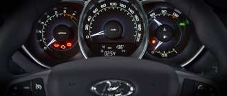
It is difficult to imagine a modern car without an on-board computer (alternative names: “BC”, “carputer”, “onborder”), which allows you to increase engine efficiency, reduce gasoline consumption, optimize the operation of the gas distribution system and synchronize the interaction of all units. In addition to the above, BC reduces the concentration of harmful emissions. The onborder performs the functions of cruise control, climate control, and displays the information necessary for the driver, allowing him to make the right decisions on transport management and optimal movement along the chosen route. That is why all modern Lada Vesta models are equipped with BCs that successfully perform the functions assigned to them.
Description of fuses on a Lada Vesta car: location, diagram, price
Lada Vesta cars are equipped with knife-type modules in the following modifications:
The manufacturer abandoned the installation of cylindrical modules 7 years ago due to the obsolescence of the model.
Relay-breaker layout diagram
| Designations | Who is responsible for what/what provides |
| K 1 | Lighting, seat heating |
| K2 | Responsible for the cigarette lighter |
| K 3 | Heated rear window |
| K 4 | Front windows |
| K5 | Interior heater (stove) |
| K 6 | Window lifter for rear doors |
| K 7 | Gasoline pump |
| K 8 | Car socket (powered by 12 Volts) |
| K9 | Heated windshield |
| K 10 | Heating relay |
| K11 | Starter |
| K 12 | Sound signal |
| K 13 | Beep (optional) |
| K 14 | Relay KSUD |
| K 15 | Air conditioning system |
| K 16 | Compressor clutch |
| K 17 | Cooling fan |
Lada Vesta fuse installation diagram
| Marking/amperage | What he is responsible for (with description) |
| F (F-1) / 20 | Windshield washer |
| F (F-2) / 5 | Understeering's shifter |
| F (F-3) / 10 | High beam (left headlight) |
| F (F-4) / 10 | Steering column switch (left) |
| F (F-5) / 20 | Heated seats |
| F (F-6) / 30 | Side lights (right) |
| F (F-7) / 30 | Left dimensions |
| F (F-8) / 7.5 | Rear fog lights |
| F (F-9) / 10 | Right turn signal repeaters |
| F (F-10) / 10 | Automated gearbox selector |
| F (F-11) / 10 | Low beam (left side) |
| F (F-12) / 10 | Direction indicators |
| F (F-13) / 30 | Power circuit |
| F (F-14) / 30 | Stop signals |
| F (F-15) / 10 | Rain sensor, external lighting, hydraulic headlight range control |
| F (F-16) / 15 | Stop light (optional) |
| F (F-17) / 15 | Illumination of the glove box, thresholds |
| F (F-18) / 10 | Turn signal repeaters (left) |
| F (F-19) / 10 | Low beam (right) |
| F (F-20) / 10 | Heated mirrors (external) |
| F (F-21) / 5 | Instrument panel (panel) |
| F (F-22) / 5 | –/– |
| F (F-23) / 5 | –/– |
| F (F-24) / 5 | ERA GLONASS |
| F (F-25) / 5 | ES9.1 controller |
| F (F-26) / 5 | Gasoline pump |
| F (F-27) / 20 | Parktronic |
| F (F-28) / 15 | Electric power steering |
| F (F-29) / 15 | Line output to tow hitch |
| F (F-30) / 20 | ERA GLONASS (optional) |
| F (F-31) / 15 | ERA GLONASS (optional) |
| F (F-32) / 15 | Engine compartment lighting |
| F (F-33) / 5 | Window lifters |
| F (F-34) / 15 | Steering wheel rotation sensor |
| F (F-35) / 5 | Door program block |
| F (F-36) / 15 | Radio, diagnostic connector |
| F (F-37) / 15 | Stop light (optional) |
| F (F-38) / 15 | Stop light (optional) |
| F (F-39) / 15 | Daytime Running Lights |
| F (F-40) / 20 | High beam (right) |
| F (F-41) / 20 | Standard cigarette lighter |
| F (F-42) / 20 | Bus power |
| F (F-43) / 20 | Door locks |
| F (F-44) / 20 | Window lifters |
| F (F-45) / 20 | Heater fan (interior) |
| F (F-46) / 20 | Windshield wiper (windshield wipers) |
| F (F-47) / 15 | PDS, LBS, LGO |
| F (F-48) / 15 | Windshield wiper (optional) |
| F (F-49) / 15 | PTF, ZPTO, license plate |
| F (F-50) / 15 | PDS, LBS, LGO (optional) |
| F (F-51) / 70 | Electric power steering |
| F (F-52) / 30 | Heated rear window |
| F (F-53) / 40 | Stability Program (ESP) |
| F (F-54) / 15 | Air conditioning system |
| F (F-55) / 5 | Reservation |
| F (F-56) / 15 | Automatic transmission |
| F (F-57) / 15 | Reservation |
| F (F-58) / 70 | Transmission optional |
| F (F-59) / 15 | Air conditioner |
| F (F-60) / 15 | Fuse supply circuit |
| F (F-61) / 60 | Generator |
| F (F-62) / 10 | Beep (optional) |
| F (F-63) / 5 | Reversing light |
| F (F-64) / 15 | Anti-theft alarm |
| F (F-65) / 15 | central locking |
| F (F-66) / 20 | Canister, air flow sensor, timing valve |
| F (F-67) / 15 | Fuel pump, charging |
| F (F-68) / 15 | Reservation |
Causes of fuse failure
- Failure to comply with the scheduled technical inspection schedule;
- Installation of non-original spare parts;
- Unprofessional installation;
- Mechanical damage to adjacent mechanisms and units;
- Short circuit in the wiring;
- Damage to the insulating layer;
- Oxidation of contacts;
- Loose fixation of terminal blocks;
- Condensation formation, moisture penetration into the structure.
OBD 2 pinout
Brands and years:
Gasoline passenger cars and light commercial vehicles manufactured or imported into the United States since 1996 (US CARB and EPA legislation) and in Europe (EOBD) since 2000-2001 (European Union Directive 98/69EG) and Asia (mainly since 1998). ).
Conclusions and their purpose:
| № | Color | Purpose |
| 2 | J1850 Bus + | |
| 4 | Body grounding | |
| 5 | Signal Ground | |
| 6 | Line CAN-High, J-2284 | |
| 7 | K-line diagnostics (ISO 9141-2 and ISO/DIS 14230-4) | |
| 10 | J1850 Bus- | |
| 14 | Line CAN-Low, J-2284 | |
| 15 | L-line diagnostics (ISO 9141-2 and ISO/DIS 14230-4) | |
| 16 | Power supply +12V from battery |
Diagnostic connector pins for used protocols
Pins 4, 5, 7, 15, 16 - ISO 9141-2.
Pins 2, 4, 5, 10, 16 - J1850 PWM.
Pins 2, 4, 5, 16 (without 10) - J1850 VPW.
The ISO 9141-2 protocol is identified by the presence of pin 7 and the absence of pins 2 and/or 10 on the diagnostic connector.
If pin 7 is missing, the system uses the SAE J1850 VPW (Variable Pulse Width Modulation) or SAE J1850 PWM (Pulse Width Modulation) protocol.
All three data exchange protocols operate via a standard OBD-II J1962 connector cable.
Where can I buy?
You can buy it at a dealership, but in the showroom it is usually very expensive. As an alternative site, you can use the resources presented in the table below. However, it is worth considering that prices may vary, and the part is not always available.
| Online store | vendor code | Price, rub.) |
| lada-vesta-shop.ru | 231A03142R | 10100 |
| www.zzap.ru | 231A03142R | 7430-8890 |
| autopiter.ru | 231A03142R | 11511 |
| avtoazbuka.net | 231A03142R | 8888 |
| renault-largus.ru | 231A03142R | |
| www.auto-tech.ru | 231A03142R | 8890 |
| www.avtogrin.ru | 231A03142R | 10500 |
As you can see, the price of an additional Vesta body electronics unit is quite high, so the replacement is not cheap. However, all work in the service center takes no more than 60 minutes.
Problems when paying with bank cards
Sometimes difficulties may arise when paying with Visa/MasterCard bank cards. The most common of them:
- There is a restriction on the card for paying for online purchases
- A plastic card is not intended for making payments online.
- The plastic card is not activated for making payments online.
- There are not enough funds on the plastic card.
In order to solve these problems, you need to call or write to the technical support of the bank where you are served. Bank specialists will help you resolve them and make payments.
That's basically it. The entire process of paying for a book in PDF format on car repair on our website takes 1-2 minutes.
If you still have any questions, you can ask them using the feedback form, or write us an email at
Comments
TOP materials of the week
TOP products in the store (more)
Your review of the sound insulation of the Lada Vesta:
Lada.Online
Lada (“Lada”) is a brand of cars produced by JSC AVTOVAZ. Previously, it was used only for export cars, and for the domestic market, cars were produced under the Zhiguli brand. In 2004, the management of AVTOVAZ announced the transition to the Latin alphabet for the official spelling of the names of all cars produced by the plant: Lada - instead of "VAZ" and "Lada".
Lada.Online is the largest Russian-language automotive resource with a daily audience of thousands, which is dedicated primarily to cars of this brand, the domestic automotive industry and the automotive world in general.
Diagnostic options for LADA VESTA electronic control units
The Lada Vesta uses a CAN-type interface, through which signals are transmitted between vehicle systems. Problems are diagnosed using an ELM327 scanner using the OBD2 protocol. List of special functions:
- Rebooting the engine control unit, resetting cruise control, speed limits.
- Training of an automatic transmission during operation. Resetting settings.
- Adaptation of steering sensor, acceleration.
- Reset instrument panel adjustments, multimedia.
- Removing protection, initializing VIN.
- Resetting the adaptation of the power steering, speed sensor, steering angle.
- Download and install one of the scanning programs.
- Carry out diagnostics of the control unit according to the adapter instructions.
- Receive and decipher codes.
- Perform adjustments or repairs to eliminate malfunctions of the device.
- Check again for errors.
Photo source: https://www.drive2.ru/l/551830318525449864/
The scanner is capable of monitoring vehicle modes and parameters while driving via OBD2.
Switches under the steering wheel on a Lada Vesta car are used to control the glass washer and wipers, turn signals, as well as to control the light.
Let's start with the right steering column switch. The main functions are control of the windshield wipers and washer. Control:
Pull towards yourself - pour water on the windshield, the wipers will make up to three strokes (depending on the time of watering)
Pull down - quickly clear the windshield, one wiper cycle
Switch up one step (—) - intermittent operation of the wipers with variable intensity. The interval between wiper strokes is adjusted using a rotating wheel.
Switch up two steps (1) - intermittent wiper operation with low glass cleaning speed (long pause between wiper strokes)
Switch up three steps (2) - intermittent wiper operation with high glass cleaning speed (short pause between wiper strokes)
Now the left steering column switch. The main function is to control turn signals, lighting, headlights and flashlights. Controls: Pull up - turn on the right turn signal;
Pull down to turn on the left turn signal;
Turn the tip of the switch one notch to turn on the dimensions;
Turn the tip of the switch two notches - turn on the low beam + dimensions;
Turn the ring one notch to turn on the front fog lights;
Turn the ring two notches to turn on the rear and front fog lights;
Press the switch away from you to turn on the high beam;
Pull the switch towards you - briefly turn on the high beams (blink high beams)