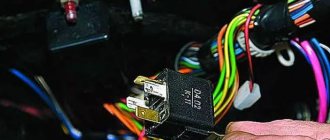
Hello to all subscribers! One of the common situations that happens, usually unexpectedly, is that the usual buzzing of the electric fuel pump in the rear of the car is absent when the ignition is turned on. As a result, the car engine refuses to start. I present an algorithm of actions if such a disaster suddenly happens. To begin with: photo 1 shows a fragment of the electrical circuit of the fuel pump.
Attention, working with electrical equipment is dangerous. If you are unsure, seek the help of a qualified professional.
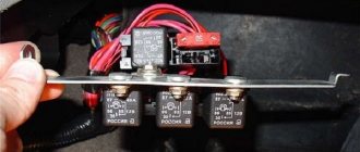
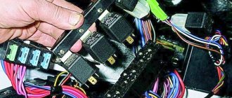
First of all, the driver should first remove the side console on the passenger side (there are 3 relays with fuses there). Our electric fuel pump relay is the lower one. (Some cars from 2007 have 2 relays, but the fuel pump relay is the top one - see the repair manual). Directly above the bottom relay is our fuse. The first step is to make sure that this fuse is working properly (photo stage 1).
If the fuse is working and its contacts and its connector are not oxidized, then you need to make sure that the relay is working properly. You can immediately install a known-good relay and turn on the ignition. If the situation is corrected, then install the side console and have a good trip. If nothing has changed, then it is necessary to determine where the problem arose. To do this, you need to have a voltmeter or multimeter or a probe. But we will not determine the voltage value with a probe, and in this situation you need to know the voltage value - I’ll tell you why later. The second step (photo step 2) is to determine whether there is control voltage at the fuel pump relay. We connect the multimeter, turn on the ignition and determine the voltage value. If there is no voltage, then there is an open circuit coming from the main relay or from the ECU. If there is tension, then move on.
Stage 3 (photo stage 3) is to determine whether the power goes further directly to the fuel pump itself. If the power does not come out, the culprit is most likely the relay due to possibly burnt contacts. If the voltage goes away, but its value is 10 volts, then most likely the relay contacts are also burnt. At this voltage, the pump motor will not start. We change the relay and check. If the power goes further and its value is 12 Volts, then the culprit is the wires going to the electric motor of the pump or the pump itself.
Next you will have to remove the rear seat to get to the electric fuel pump. We remove the hatch and see the fuel pump chip. There are 3 wires on the chip: 1-minus, 2-plus of the fuel level sensor, 3-plus of the fuel pump itself. Unfortunately, I won’t tell you the sequence and location on the chip yet. In any case, when the ignition is on, there should be 2 pluses and one minus. In photo 4 (photo stage 4) we connect one by one to the contacts of the fuel pump chip and look at the presence and magnitude of voltage. If there is voltage, then the culprit is the electric fuel pump itself, and without removing it, most likely the cause cannot be eliminated.
Be careful with electricians and remember that the fuel pump control circuit can also break a faulty security alarm relay. Smooth roads everyone.
Tips for motorists
The electric fuel pump on a VAZ-2114 passenger car is located in the fuel tank, and after the ignition is turned on, voltage is supplied to its terminals through a 15 amp fuse F3 and relay R2, located under the panel on the passenger side in the car interior.
The first thing the driver of the “fourteenth” does after the fuel pump fails is to unscrew the two screws that secure the cover on the right side of the console under the panel, covering three relays and three fuses, and check the integrity of fuse F3, which is located next to two relays located one behind the other and the state of the contacts where the fuse is inserted. If it is intact, you need to check the fuel pump relay (you can replace it), which is located next to the fuse (it is the middle one among the relays available there).
If everything is in order with the fuse and relay, then the driver’s next action will be to get to the fuel pump terminals. To do this, you will have to lift the rear seat cushion and remove the cover at the bottom of the car body by unscrewing the screws that secure it. In the opened hatch you will see three terminals, one of them is negative, and two are positive (gray and black wires), which supply voltage to the fuel pump and fuel level indicator. You have to check whether voltage is supplied to the positive terminal of the fuel pump motor. This can be done using a control lamp. When you turn on the ignition, it should light up for 3-5 seconds (this is the time it takes to pump gasoline from the tank into the fuel rail before turning on the starter).
If the light comes on and the fuel pump does not work, this means that voltage is supplied and you need to check its value using a tester, since if the voltage is below 10 volts, the electric motor of the fuel pump will not start. The voltage drop occurs due to oxidation of the contacts, so you will have to check the condition of the contacts of both the negative and positive wires. You can also check the serviceability of the fuel pump by applying voltage to its terminals directly from the battery using two long wires. If the above actions do not help, then the fuel pump will have to be removed from the fuel tank and either replaced with a new one, or disassembled and looked for a fault inside it (for example, the brushes are stuck or worn out).
Diagnostics
A malfunction of the VAZ 2114/2115 fuel pump can be caused by:
- malfunctions in the device’s power supply circuit;
- failure of starting and protection elements (relay and fuse);
- wear of electric motor parts.
Checking the electrical circuit
At the beginning of the diagnosis, you should check the electrical circuit of the fuel pump. To do this you will need:
- car tester (multimeter);
- crosshead screwdriver;
- two pieces of wire about 2 m long.
Checking the electrical circuit is carried out in the following order:
- Turn on the ignition without starting the engine. When the key is in the first position, a click should be heard, characteristic of turning on the relay, followed by a slight whirring of the pump electric motor. If there is no click, the relay is faulty or is not receiving power. If there is a click, but no buzzing, the wiring coming from the relay or the pump motor itself is faulty.
- Under the glove compartment, find an additional mounting block consisting of three relays and three fuses. The pump relay is located in the middle, and the fuse is located to the left of it. Remove the fuse from its socket, test it with a multimeter, and if the result is negative, replace it. When replacing the fuse, please note that it is rated for a maximum of 15 A.
- Set your multimeter to voltmeter mode. Connect one probe of the device to the relay terminal to which the pink wire fits, and the second to the car body. Turn on the ignition. The device should show the on-board network voltage in the range of 11.7–12.4 V. If there is no voltage, the problem may be a broken wiring or a malfunction of the ignition contact group. In this case, it is better to contact an auto electrician. If power is supplied, check that the relay is working. With the ignition on, use a screwdriver or a piece of wire to close the contacts to which the pink and gray wires go. This closes the circuit bypassing the relay. If the fuel pump works, replace the relay.
- Be sure to check the connection of the pump's negative wire to ground. Often it is the lack of “ground” that causes interruptions in the operation of the fuel pump. Remove the plastic trim from the center console near the parking brake handle. Under it there is a “negative” wire of the pump, screwed to the body with a self-tapping screw. Unscrew it, clean the contacts, screw it back and repeat the test.
- Then check the fuel module. Remove the rear seat, peel back the carpet and sound insulation. Unscrew the two screws securing the gas tank flap and disconnect the electrical connector on the fuel module cover. Using two wires, supply power to the pump directly from the battery. If the pump works, the wiring is faulty; if it doesn’t work, the pump itself is faulty.
Pressure check
If the pump is working properly, but the engine begins to operate intermittently, you should check the fuel pressure in the system. For this you will need:
- pressure gauge (can be a tire gauge with a measurement limit of 5–7 kPa);
- petrol-resistant hose with a diameter of 10–12 mm and a length of 50–80 cm;
- two clamps for a hose of the appropriate diameter;
- Phillips screwdriver;
- nipple cap;
- dry rag.
The verification procedure is as follows:
- In the engine compartment on the engine fuel rail, locate the pressure measuring fitting (on the right side).
- Remove the plastic cap (plug) from the fitting.
- Using the nipple cap, unscrew the spool valve from the fitting. When unscrewing the spool valve, fuel may spray out of the fitting. To remove it, use a dry cloth.
- Place one end of a gas-resistant hose onto the fitting and secure the connection with a clamp. Connect the other end of the hose to the pressure gauge fitting and also tighten the clamp.
- Ask an assistant to turn on the ignition. Wait a few seconds and watch the meter readings. With a working pump, the pressure gauge should show a pressure of 2.8–3.2 kPa for engines with a volume of 1.5 cm3 and 3.7–3.9 kPa for engines of 1.6 cm3. If the pressure is noticeably higher, the pump is faulty.
Fuel pump fuse and its functions
The fuel pump safety device, not only on the VAZ-2114, but also on other passenger cars, is just a small element in the vehicle’s fuel system. It has a relatively small size, but carries an important functional load.
The main function of this element to protect the functions of the fuel pump is to open the conductive circuit of the automobile fuel system. This need arises in case of overload of electrical circuits. As soon as such an overload occurs, the fuse element melts as a result of the high temperature, and the electrical circuit becomes open.
The safety element is small in size, and its design is quite simple:
- the outer casing is made of plexiglass;
- inside the device there is a conductive element made of plates and fusible material;
- the body is marked in the form of the Latin letter “F” (this designation indicates that the safety device is intended for an electrical circuit with low power).
Thanks to the metal plates and the fusible material between them, the fuel pump fuse perfectly conducts electric current, but at a power that corresponds to the markings on the body of this part. If the power indicators in the electrical circuit are higher than the required value, the low-melting material immediately begins to melt, and the current-carrying circuit opens.
Thus, the fuel pump is saved from possible overloads.
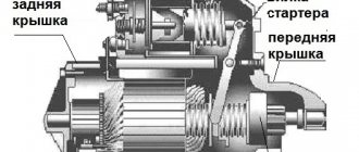
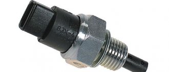
Location of the VAZ 2114 starter relay
Starter protection is designed to protect the circuit of the corresponding unit from overload or short circuit. In appearance, it is a standard four-pin device suspended on a bolt inside the engine compartment.
In this case, the injector or carburetor is designed in the same way - the block is suspended independently. The exact location of the element is impossible to describe. Thanks to the “special” approach of the designers, the hitch may differ depending on the year of manufacture. Therefore, it is best to start your search from the starter terminals and move along the wires to the device itself.
Locating the starter relay
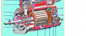
The starter retractor is an electromechanical device installed directly inside the unit housing.
The part is responsible for the clutch of the engine flywheel with the electric motor gear. The search is carried out by visual inspection. The retractor is located in the same housing as the main unit and has two large contacts coming from the ignition switch and the battery.
Retractor design
The VAZ 2114 starter solenoid relay is located on the housing of the starting electric motor and is securely fastened to it. The device consists of separate windings and a contact group.
Mechanism of action
Operating principle of the device:
- when turning the ignition key, power is supplied to the retractor winding;
- the working plate, under the influence of current, is pressed against the contacts;
- power is supplied to the starter;
- the engine turns over and the engine starts.
Signs of malfunction of the retractor relay on the VAZ 2114
There are a number of symptoms that indicate a device failure. The symptoms are specific to this part and are difficult to confuse with other problems.
Typically, masters highlight:
- nothing happens after turning the ignition key;
- the starter fires, but does not turn off, which is accompanied by a characteristic sound.
No clicking of the solenoid relay
If there is no characteristic sound of the solenoid relay operating, the problem should be looked for further:
- the contacts of the working plate have oxidized;
- there is damage to the ground cable;
- The solenoid coil of the relay is burnt out.
There is a click, but the starter does not turn
If after turning the key there is a characteristic sound, but then nothing happens, the components are checked.
- Charging the battery. If there is no voltage on the windings, clicks may appear, but the current will not be enough to start the motor.
- Damage or wear to the commutator.
- Oxidation of the retractor element.
The relay is activated, the starter starts the engine, but does not turn off
The most common cause is a clogged starter armature. In this case, the bendix wedges and its working part does not disengage. In second place is a breakdown of the ignition cylinder - the key release may not work, or the contact group does not move easily enough.
Instructions for replacing the relay on a VAZ-2114
Replacing the starter solenoid relay, as well as the engine itself, is a responsible process that requires close attention and extreme care.
Starter relay installation diagram
The electrical circuit for connecting the starter relay is not complicated. Any car enthusiast can carry out installation work, provided he has sufficient experience and a minimum set of tools.
It is also useful to know about connecting an additional relay.
How to replace the starter relay
To replace a unit, you must follow a sequence of steps.
- Securely lock the machine in place.
- Remove the terminals from the battery.
- You will need to disconnect the red wire from the relay.
- Using an open-end wrench No. 8, unscrew the screw of the brush assembly and remove the wire connected to it.
- Loosen and remove the tie rods securing the device to the ground.
- Dismantle the power cable and remove the device.
- Assembly is carried out in reverse order.
Checking work
The most reliable way to check is the “scientific poke” method. After assembling the device, you will need to start the engine. If the procedure was successful, the module operates normally.
Starter Interlock Relay Location
The starter interlock device is a separate unit that prevents the rotation of the electric motor armature after starting the power unit of the machine. Thanks to a well-thought-out design, after turning the ignition key, a group of contacts is closed, passing current to the starter. After the motor spins up and the circuit opens, the diode closes and the excited windings are de-energized.
The exact location of the block differs depending on the year of manufacture. The type of power plant also affects the installation.
Where is the fuel pump fuse on the VAZ-2114
In modern passenger cars, the manufacturer installs several special safety blocks in the current-carrying circuit at once in case of unforeseen situations that could damage the vehicle. This is done to reduce the risk of fire. Such fuses localize the entire electrical circuit to key areas where short circuits are most likely. Any vehicle has instructions that contain detailed diagrams of the location of all parts.
The VAZ-2114 also has a fuel pump safety device located under the hood. More precise location of this part:
- open the hood;
- look towards the windshield;
- there is a plastic box on the ECU;
- This box contains the fuse we need.
On the VAZ-2114 the fuse is marked as follows - Fuel Pump 15A.
VAZ 2114: fuse and relay diagram
On the fourteenth model with an 8-valve engine, two power supplies are installed. The first is located inside the engine compartment. More specifically, the block is located under the windshield on the right side in the direction of travel of the car. Externally, the device looks like a black box with a plastic lid.
The indoor unit is located in the cabin, under the feet of the front passenger on the left. The side part of the instrument panel is made in the form of an inspection hatch that provides access to the protective elements.
Connection diagram for mounting block 2114
The figure schematically shows the terminals and wiring connections of the main mounting block. The double index indicates the number of the pad and plug.
Pinout of mounting block connectors
The fuse mounting block has several terminals for connecting on-board wiring.
The following is the pinout of terminal block Ш1:
- 1 – window regulator;
- 2/3/5, 6/8 – ignition system;
- 4 – electric motor of the stove.
Ш2
- 1 – aft windshield wiper;
- 2/15 – turn signal activation buttons for left and right, respectively;
- 3 – ignition system relay;
- 4 – checking the serviceability of the lighting lamps;
- 5 – emergency warning button;
- 6 – front left door;
- 7/9/16 – reserve system output;
- 8/11/12/14 – dump controls for high beams, dimensions, handbrake displayed on the dashboard;
- 10 – rear fog light switch;
- 13 – illumination of the interior of the car;
- 17 – body weight.
Ш3
- 1 – speedometer connection line;
- 2 – emergency warning button;
- 3 – turns;
- 4 – lubricant level diode in the engine crankcase;
- 5 – mass;
- 6 – antifreeze level in the expansion tank;
- 7 – ABS control;
- 8 – switch for head optics and backlight;
- 9 /11/12/18-20 – washer control button;
- 10 – connection of a portable light bulb;
- 13 – adjustment of external lighting;
- 14 – control of dimensions;
- 15/17/21 – reserve outputs;
- 16 – oil pressure gauge.
Ш4
- 1 – monitoring and control of the stern window heating mechanism;
- 2/12 – switches between low and high beam;
- 3/8 – tidy;
- 4 – key for turning on external optics;
- 5 – tidy rheostat;
- 6/11/14 – spare terminals for connecting auxiliary equipment;
- 7 – windshield cleaning device regulator;
- 9/10 – keys for turning on the dimensions and horn, respectively;
- 13 – block of steering column switches;
- 15 – head optics wipers;
- 16-18/20 – controls for brake fluid and antifreeze levels and battery charging;
- 19 – fog light button;
- 21 – connection of an electronic tachometer.
Ш5
- 1/2/3/6 – buttons for switching on the low and high beam;
- 4 – starter;
- 5 – drive of the head radiator fan.
Ш6
- 1/4-6 – reserve contacts;
- 2/12 – reverse button;
- 3/11 – connection of the turn signals of the front of the car;
- 7 – wiper switch;
- 8/10 – dimensions;
- 9 – switch for engine compartment lamp;
- 13 – sensor in the brake expansion tank.
Ш7
- 1/4 – reserve inserts;
- 2/3 – front optics cleaner motor;
- 5 – DUM;
- 6 – horn;
- 7 – speedometer;
- 8 – DTOZH;
- 9 – generator output;
- 10/14 – BUEM;
- 11 – engine compartment lamp sensor;
- 12 – expansion tank sensor;
- 13 – ABS sensor;
- 15 – power supply to the ignition coil;
- 16 – DUOZH;
- 17 – fog light relay.
Ш8
- 1 – fog light relay;
- 2/3 – front fog lights;
- 4 – ignition coil;
- 5/6 – generator output;
- 7/8 – starter and foglight relays.
Ш9
- 1 – reserve;
- 2/9 – turn signals for the rear of the car;
- 3/18 – rear wiper motor;
- 4 – power supply for fog lights;
- 5 – tailgate door end switch;
- 6 – similar element of the front right side;
- 7/13 – “chandelier” in the salon;
- 8 – button indicating that the handbrake is turned on;
- 10/19 – heated rear window;
- 11 – number plate illumination;
- 12 – front left door;
- 14 – feet;
- 15/17 – dimensions;
- 19 – heated rear window.
Interpretation of fuses and relays of injection models
Injection-type models use a different mounting block design. Consequently, the arrangement of elements and fuse links may differ.
For example, we take a diagram of a mounting block type 3722010-60
| Item number | Area of responsibility |
| F1 | Aft fog lights |
| F2 | Hazard alarm and turn signals device |
| F3 | Lighting devices and control lamps |
| F4 | Heated rear window and terminal for connecting a portable lamp |
| F5 | Radiator Fan Fuse |
| F6 | Window lifters |
| F7 | Heater motor, cigarette lighter, heated rear window |
| F8/9 | Front fog light switches |
| F10 | Illumination of the instrument panel and indication of warning lamps, left side of the dimensions |
| F11 | Right side side lights |
| F12/13 | Low beam headlights |
| F14/15 | Long range lighting |
| F16 | Turn signals and their breaker |
| F17-20 | Reserve sockets |
Separately, you should consider the protective inserts of the fuse box.
| Number in the diagram | Purpose |
| K1 | Wiper drive |
| K2 | Turns and emergency lights |
| K3 | Lobovukha cleaner |
| K4 | Control of dimensions and turn signals |
| K5 | Power windows throughout the car |
| K6 | Klaxon |
| K7 | Heated stern window |
| K8/9 | Long and short range operation of head optics |
Decoding fuses and relays of block 2114-3722010-18
Older injection-type models are equipped with different fuse blocks. Here the location of the fuse links is as follows:
- F9/8 – fog lights;
- F1/7 – head optics cleaners, their contacts and valves, glove compartment lighting, equipment warning lamps;
- F16 – turn signals, hazard warning switch, oil pressure, TPS and handbrake indicator lamps;
- F3 – interior lighting, reversing lamp;
- F10 – fuse for rear license plate illumination, engine compartment lighting, dimensions control, cigarette lighter illumination, heater buttons, left side of dimensions;
- F11 – right side of dimensions;
- F2 – control of emergency gang operation;
- F4 – power fuse protecting the heated stern glass, portable socket;
- F15 – high beam head optics;
- F14 – light switching controller and corresponding lamp;
- F13/12 – right and left low beam.
Additionally, there is a decoding of the protective relays
- K1 – protective insert for headlight washers;
- K2 – emergency lights and turns;
- K3 – windshield wipers;
- K4 – indication of warning lamps;
- K5 – activation and operation of power windows;
- K6 – horn circuit;
- K7 – heated rear window;
- K8/9 – low and high beam headlights.
Explanation of the additional fuse and relay block
The auxiliary block does not have a large number of protective inserts. There are only three relays and fuses here:
- 1 – main distributor relay;
- 2 – controller power supply;
- 3 – pump protection.
There is also an equal number of control inserts:
- K4 – fuel pump;
- K5 – head radiator fan;
- K6 – main relay of the controller.
Checking the fuel pump fuse on a VAZ-2114
Experts recommend regularly checking the fuel pump safety device on the VAZ-2114. The easiest way to get to this part is from under the hood, that is, from the outside of the vehicle. To do this, you must follow the following step-by-step instructions:
- Open the hood lid.
- Find the plastic box on the engine control unit.
- Open the small unit, which opens and closes with latches.
- Find the appropriately marked safety device (located at the top).
- Remove the safety element:
- for this you will need forceps, tweezers or a clamp;
- grab the safety device with a tool;
- pull the fuse towards you;
- remove from the nest.
- Perform a visual inspection of this device:
- cracks and chips on the body;
- burnt fusible materials inside;
- carbon deposits on the internal plates;
- contacts are damaged.
If the contacts of the safety device are intact, then it can still function. But in such cases it is not worth the risk; it is best to replace the damaged part with a new one.
If there are obvious signs of combustion on the fuel pump safety device, replacing it will not be enough. You will also need to check other details:
- the entire section of the current-carrying circuit for breaks in it;
- pump relay (may stick);
- fuel pump contacts (terminals may oxidize);
- the fuel pump itself.
According to the marking, the safety element accepts a current of 15 A; you can find a similar one for sale in specialized stores without much difficulty.
Experts warn that if the breakdown problem lies not in a blown fuse, but in another part or in the wiring itself, replacing it will not be enough. It is necessary to determine the reason why this element failed. If this is not done, the new fuel pump fuse will burn out in the same way as the previous one.
Rail pressure VAZ 2114
What to do if the fan on the VAZ 2114 (2115,2113) does not work?
What exactly is a fuel pump? This is an element of the fuel system that allows fuel to pass through due to pressure. Therefore, if you take pressure measurements, you can get answers to many questions. Let's give an example of normal pressure readings when checking in certain modes.
| Check mode | Normal indicator |
| At idle | 2.5 atm |
| When ignited | from 3 atm |
| Without pressure regulator tube | 3.3 atm |
| When the drain is pinched | 7 atm |
| When you press the gas pedal | 3-2.5 atm |
We recommend measuring with a small range of atmospheres on a pressure gauge (up to 7 atm). This will reduce errors to a minimum. Having a pressure gauge at hand will allow you to significantly save on professional diagnostics.
Contacts
The fuel pump includes three wiring:
• Plus (positive); • Minus (negative); • Fuel level indicator. So, failure of the pump may occur due to a simple violation of the integrity of the wires. So if the pressure check shows normal, then we definitely examine the condition of the wiring. To check, you will need a 12V lamp, which is attached to the external connectors of the pump with positive and negative contacts. Turn the ignition key. If the lamp blinks, contact is present. In this case, you will have to check the condition of the internal contacts.
Checking the contacts of the fuel pump VAZ 2114
Fuel pump motor VAZ 2114
If the pressure and wiring are normal, let's try to check the serviceability of the motor. It is this element that is responsible for moving fuel through the system. • To check it, you will need the same 12V lamp; • Attach it to any motor terminal; • Turn the ignition key; • If the lamp blinks, you will have to get rid of the motor and buy a new one.
Don't jump to conclusions. Before checking, look at the condition of the terminals and motor wiring.
Weight
The contacts are fine, but the fuel level sensor may provide incorrect information. In this case, you definitely need to check the weight of the pump responsible for dispersing the fuel. It often turns out that after prolonged use or driving on difficult road sections, the mass simply loses its fastening strength. Accordingly, if the mass falls off, the pump will not be able to work. The mass is attached to the pump under the dashboard in the area of the hand brake. Therefore, when the driver turns on the handbrake, there is a possibility of hitting the ground contact, which is why it will fall off. Putting the mass back in place is not that difficult. The problem is caused by the path to it. You'll have to:
• Get to the bottom through the interior; • Remove the plastic under the handbrake; • Remove the floor covering; • Remove the grounding contacts; • Clean; • Attach it to the fuel pump as firmly as possible.
Fuel pump relay VAZ 2114
The fuel pump relay is located exactly where the ground is. Therefore, there should be no problems with the search. With an ideally working fuel supply system, when the ignition is turned on, the relay instantly creates pressure inside the system, and then turns off.
If this process is disrupted, you will have to:
• Lift the front facing panel, which covers the contacts of the audio system and air conditioning; • Look from the front passenger side; • Find three relays; • The lowest one is our desired pump relay; • Turn the ignition key; • If you hear a characteristic click from the relay, it is working properly; • If there is no click, check the contacts. The reason is either them or a failed relay.
Fuel pump fuse VAZ 2114
All that remains is to check the condition of the fuse. This stage will make sure who the real culprit of the problems is - the pump itself or its fuse.
• Getting to the fuse is as easy as getting to the relay - through the hood or from the inside. The first option is preferable. • Raise the hood and look in the area near the windshield. • There is a dark-colored box located directly on the electronic engine control unit. • Open the drawer and look inside for the topmost fuse. • It has a current strength of 15A, as well as an inscription in English - Fuel Pump, that is, a fuel pump. • Examine its external condition by removing it from the box. • If the contacts are intact, then everything with the fuse is normal. • If burnt contacts are clearly visible, consider purchasing a new device. Its price is affordable, so finding and replacing should not be a problem.
Fuel pump fuse VAZ 2115
The fuel pump relay is located under the dashboard. On the passenger side, a side panel is opened that covers the beard on which the radio, on-board vehicle, and heater controls are mounted. We see a strip with three relays and fuses.
The pump relay is the lowest. Its fuse is also at the very bottom. When you turn the key, the relay turns on for 5 seconds in order to pump up pressure in the system and turns off. After the engine starts, control of the pump passes to the computer.
The mass of the pump (and fuel level sensor) is attached to the stud securing the handbrake to the body under the carpet. To get to it you need to remove the vestibule between the passenger and driver seats. There are 3 wires going to the fuel pump. first +, second minus, third fuel level sensor.
Replacing the pump on a VAZ
When all the measures described above do not help, you will have to seriously look at the fuel pump. In particular, it is definitely necessary to clean the primary filter, and the unit itself is replaced only if necessary, when there is no doubt that it has become unusable.
The replacement procedure is as follows:
- disconnect the negative connector from the battery;
- remove the rear seat;
- remove the hatch;
- disconnect the two outer wires supplying power and fuel lines;
- unscrew the bolts holding the pump;
- pull it out.
Do not rush to remove the unit from the VAZ-2114 injector; act carefully - there is a risk of damaging the float. Clean the filter mesh and install a new fuel pump in reverse order.
After installation, you need to check whether it will work. Turn on the ignition and start the engine. Next, measure the pressure in the system with a pressure gauge.
Clean the filter mesh and install a new fuel pump, proceeding in reverse order. After installation, you need to check whether it will work. Turn on the ignition and start the engine. Next, measure the pressure in the system with a pressure gauge.
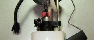
Operating principle and design features
The VAZ 2114 fuel pump is located inside the car’s gas tank, which is why access to it can be problematic if you don’t know which side to approach. To free up access to the fuel pump, you need to remove the rear seat from the fourteenth, under which you will find a rectangular hatch hiding access to the fuel module.
Just fold back the back seat and see for yourself
In addition to the pump itself, the VAZ 2114 fuel module includes:
- A float sensor that monitors the fuel level in the gas tank;
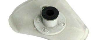
- Chamber for fuel intake;
- Mesh filter for coarse cleaning.
The gasoline pump has a built-in electric motor, which pumps up the pressure of the pumped fuel. The motor itself is powered from the vehicle's on-board network. The VAZ 2114 gasoline pump is located so that even with a minimum level of fuel in the tank, it is constantly washed with gasoline, as this is necessary for normal cooling of the unit, which gets very hot during operation.
The main working element of a gasoline pump is a membrane, which during operation performs reciprocating movements. During normal operation, when the device is fully operational, the following pressure levels must be maintained in the fuel rail:
- For 1.5 l engine. – from 285 to 326 kPa;
- For 1.6 liter engine. – from 375 to 390 kPa.
As evidenced by reviews from owners of fourteenth VAZs, in practice BOSCH pumps have proven themselves to be the best.
Unlike domestically produced units, they cost almost 20-30% more, but at the same time they have an order of magnitude better build quality and reliability. The estimated cost of the fuel module for a 1.5 liter engine of the fourteenth is 2.5 thousand rubles, for 1.6 liters. – 2.6 thousand
However, rational savings are possible here - in most cases it makes sense to purchase a fuel pump separately, rather than the entire module, since, as a rule, the pump itself “dies”, and the remaining parts of the module remain in working order. Its cost, if taken separately, is 1-1.5 tr.
which power supply is responsible for the cigarette lighter, fuel pump and heater
The VAZ 2114 fuse box is a device within which all the safety components that provide protection for certain devices are concentrated. If problems occur in the operation of automotive equipment, the first thing to look for is a blown fuse. You can read more about the electrical circuit, as well as replacing the power supply, below.
Location and electrical diagram
What is the power supply circuit in the Chetyrka, the injector, where is the fuse (fuse) for the fuel pump and the cigarette lighter, which fuse is responsible for the instrument panel? All working parts are located in the power supply unit, which, in turn, is installed in the engine compartment, if you look at the car in front, then on the left, opposite the driver’s seat. If there is an overvoltage in the power grid, it is the PP that burns out first (the author of the video is the Ramanych channel).
The Fours, like all other domestically produced cars, use a single-wire on-board network system. All equipment that consumes energy is connected to the power supply and is equipped with its own switch, which opens the circuit in case of overvoltage. This occurs in order to prevent overheating of the wires and, accordingly, a possible fire. But you need to take into account that not all consumers are protected by safety devices in the unit. Some equipment draws more voltage, such as the coil circuit, battery circuit, or engine starting system.
If you open the lid of the box, you will be able to see the location and electrical circuit of the power supply - the device contains 9 relays and 20 PPs. On the back of the cover there is a diagram of the parts - with its help you can find out the purpose, that is, which fuses are responsible for the stove, dashboard lighting, central locking, etc. It’s worth mentioning separately about the control panel. Many car enthusiasts, faced with a problem when the backlight on the dashboard does not light up, begin to disassemble the panel and look for a problem in the power supply, but this is not entirely true. First of all, it is recommended to check the PP number f16 - it is responsible for the dashboard lighting.
Now let's take a closer look at the purpose of the elements in the block, starting with the relay:
- K1 - protects the front light brush circuit from overvoltage;
- K2 - protects the electrical circuit of the turn signals and alarms from overvoltage;
- K3 - detail for protecting the electrical circuit of the windshield cleaning system;
- K4 - allows the light source to operate in normal mode, ensuring the operation of other light bulbs;
- K5 - such relays are equipped with cars equipped with electric windows, it is responsible for their operation;
- K6 - this relay is used to protect the horn - steering wheel horn circuit;
- K7 - provides protection for the electrical circuit of the rear window heating system;
- relays K8 and K9 are used to ensure the operation of lighting sources in low and high beam lamps.
Instructions for removing and replacing the power supply with your own hands
Replacing a power supply unit is not a particularly complicated procedure, but if you have never encountered the need to perform this task before, then it makes sense to entrust the procedure to an electrician. However, there is nothing difficult about this, so if you strictly follow all the steps indicated in the instructions, you can perform this procedure yourself. To complete this task, you only need a new power supply and a 10mm wrench.
Stages
So, how to remove and replace the power supply with your own hands:
- First you need to turn off the ignition and open the hood. The power supply itself, as mentioned above, is located in the niche between the engine and the glass, opposite the driver’s seat. The device has a plastic cover, it is fixed on plastic fasteners. You need to press the lid with your finger and lift it, then remove it.
- Remove all parts from the installation locations. The PPs differ from each other in their nominal values; during further installation, it is important that they are installed correctly according to their nominal values.
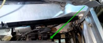
- Then you will need to remove the plugs that are connected from the engine compartment directly under the power supply. To gain access to the connectors, it is necessary to dismantle the plastic protective casing, it is marked with the middle arrow in the figure below. The casing itself is fixed using plastic clips. The other two arrows in the photo mark the bosses on the bracket; these clips are inserted into them and need to be removed. Removal is carried out using a flat-tip screwdriver. Please note that the clips themselves will most likely break during dismantling, since they harden over time, so new ones will be required for further installation.
- After the connectors in the engine compartment are disconnected, you will need to disconnect all the plugs that are located in the cabin. They can be found behind the steering column; in some Fours they are closed using sound-proofing material. When disconnecting, we recommend marking the connectors so that there are no problems with future connections.
- When all the pads are disconnected, we proceed to dismantling the power supply itself. The device is fixed on two nuts, which you need to unscrew using a 10mm wrench.
- The power supply unit is removed, after which its seat must be thoroughly cleaned. After completing these steps, the device is replaced with a new one. The power supply must be securely fixed in the installation location; to do this, tighten the bolts that secure it as much as possible. Connect all connectors, install the PCB and relay in place, and then check the functionality of the installed device. If you did everything correctly, the new power supply will work.
Signs of a fuel pump failure
A faulty fuel pump is quite easy to identify, since it is characterized by characteristic signs of failure. For example: while driving, the car suddenly stalls - after turning it on again, the engine begins to make uncharacteristic sounds, while the starter does not stop turning. After the car starts up, the picture repeats itself - the fourteenth engine stalls again. It is also possible that the car starts every once in a while - problems usually arise after sitting at neutral speed.
Let's determine the most typical signs of a fuel pump malfunction:
- The engine refuses to start. Of course, there can be many reasons for this problem - the same spark plugs, or the ECU, but the possibility of a fuel pump malfunction is also worth taking into account;
- The pressure level in the fuel relay differs from normal values;
- The motor is tripping. As a rule, if the fuel pump does not pump as it should, the engine begins to twitch quite noticeably because gasoline is not burned properly in the working cylinders;
- The engine growls at low speeds. One of the most truthful signs, which indicates either an immediate breakdown of the pump, or that the low-purity filter is clogged and the mesh needs to be replaced.
There are quite a lot of possible breakdowns that could cause the fuel pump to fail. The following parts of the unit design can present an unexpected surprise: fuse, fuel pump relay, ground, electric motor, contact system. Let's look at each of them separately.
Pressure level
In order to get most of the picture of what is happening, it is enough to measure the pressure in the fuel rail. For this, it is necessary to use a pressure gauge that has a small measurement range (preferably up to 7 atmospheres), since devices with a large range can produce significant inaccuracies.
Rail pressure measurement
Under the hood of the fourteenth there is a pressure fitting; unscrew its cap and connect the pressure gauge to it. Normal indicators should be as follows:
- When the engine is idling – 2.5 kPa;
- At the moment of ignition - 3 kPa;
- With a pinched drain hose – 7 kPa;
- When gaining speed - 2.5-3 kPa.
If the pressure gauge needle does not move when the ignition is turned on, then the gasoline pressure regulator is most likely broken. When there is no change as the speed increases, the fuel pump itself has failed, but if the needle moves very slowly, which indicates that the pump is pumping, but poorly, the fuel pump screen is clogged.
Checking wiring contacts
If the fuel pump does not work, do not rush to change it - perhaps the problem is in poor-quality wiring. There are 3 wires connected to the pump: to the gasoline level sensor, and positive and negative to power the motor.
No special tools are required to check the wiring - a regular 12-volt light bulb is enough. We connect the light bulb to the negative and positive wires of the pump, and turn on the car’s ignition - if the light blinks, then everything is fine with the wiring.
When you have determined that the external wiring of the fuel pump is normal, you need to move on to checking the motor. This is done with the same light bulb, the wires of which are connected to the external terminals of the motor. If the light comes on when you turn on the ignition, then you need to change the motor.
Symptoms of a problem
A malfunction of the fuel pump of VAZ 2114/2115 cars can be diagnosed by the following symptoms:
- when the ignition is turned on, there is no sound of the pump running;
- the engine does not start or starts with difficulty;
- the power unit is unstable at idle, the speed “floats”;
- “dips” appeared during acceleration;
- the motor has lost power.
The same signs also appear when other elements of the fuel system malfunction.
Before you begin diagnosing or replacing the fuel pump, you should make sure that:
- the fine fuel filter is not clogged (it is changed every 7 thousand kilometers);
- the injectors and fuel pressure regulator are operating normally;
- The sensors for mass air flow, throttle position, and oxygen quantity are working properly.
If the detected malfunction is accompanied by the lighting of the “CHECK” lamp on the dashboard, you should set the error code and decipher it.
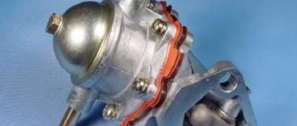
Fuel pump ground and relay
In the fourteenth, the mass of the fuel pump is fixed under the dashboard, next to the handbrake lever, during use of which the mass can be touched and shifted from its normal position. To fix this, remove the plastic around the handbrake, clean the ground contacts and reattach it.
Next to the ground there is a VAZ 2114 fuel pump relay. The relay is necessary so that during ignition the required pressure level is immediately created in the system.
A few words about where the fuel pump relay is located: after removing the plastic around the handbrake, you will immediately find 3 different relays - one of them is from the fuel pump.
It is better to immediately replace a broken relay with a new one; it is not expensive.
How to change the pump
If it turns out that the relay for the VAZ 2114 fuel pump, the motor, the ground contact, and all other electrical elements of the circuit are working, all that remains is to replace the damaged pump with a new one.
You can do it like this:
- Disconnect the battery ground terminal.
- Drain the fuel from the tank.
- Remove the rear passenger seats.
- Remove the plastic cover covering the pump.
- Disconnect the wires and hoses going to the pump.
- Unscrew the fuel pump fasteners using a size 7 wrench.
- Remove the pump from the tank.
Installing a new fuel pump is done in exactly the same order, but in reverse order.
Checking the fuse
First, let's figure out where the VAZ 2114 fuel pump fuse is located: you can find it under the hood, on the windshield side. There is a drawer on the electronic control unit that needs to be opened. In the box we need a fuse that says Fuel Pump 15A above it. If the fuse for the VAZ 2114 fuel pump is blown, you need to install a new one.
The fuse blows due to incorrectly connected alarm contacts or the anti-theft system.
Changing the fuel pump yourself
If the fuel pump in the VAZ does not pump, and all of the above system components are normal, it is necessary to clean the filters, and, if necessary, completely replace the unit.
Before starting work, you must completely drain the fuel from the gas tank. To do everything with our own hands, we need a screwdriver and a set of keys. Replacing the VAZ 2114 fuel pump is carried out according to the following algorithm:
- We de-energize the car by removing the “-” terminal from the battery;
- We take out the rear row of passenger seats;
- Unscrew the plastic cap that covers the pump;
- Remove the power wires from the device and disconnect the fuel supply hoses;
- We dismantle the main fastenings of the fuel pump; for this we need the 7th key;
- Now you can remove the fuel pump on the VAZ 2114 and remove the device.
It must be removed carefully, since the float sensor for determining the fuel level is a very delicate structure that is easy to damage . Inspect the fuel pump - if necessary, clean or replace the strainer, however, it may be necessary to completely replace the unit.
We study the signs of a fuel pump failure if it does not pump fuel
The non-pump is one of the key components of the VAZ 2114 fuel module. The gasoline pump helps ensure that gasoline is supplied to the engine at the required level of pressure.
Fuel pump for VAZ 2114
Any guarantees from the manufacturer with the actual service life of the fuel pump have little in common, since its durability directly depends on the operating conditions - even the highest quality VAZ fuel pump can quickly fail due to bad gasoline.