Many motorists, especially beginners who have just purchased a VAZ-2114, have wondered how the 8-valve injection engine that is installed on this car works. This article will discuss the design of the motor, its main characteristics, as well as dismantling and repair features. This information will be very useful for beginners and those who do not know how the main power unit works.
Video about the VAZ-2114 engine
Video review of the VAZ-2114 engine operation, features and characteristics.
Relay and fuse block diagrams for VAZ 2115
The Lada 2115 was first released in 1997 and finished production in 2012. Over such a long period of time, the electronic components of the car have changed significantly.
It is not surprising that modifications of the mounting blocks have changed more than once, and with them the fuses of the VAZ 2115. An old-style car with a carburetor required one installer in the engine compartment. With the advent of a new 8-valve injector, a second unit was needed, installed in the cabin under the dashboard. Some of the new relays were placed under the steering wheel during the 2007 and 2008 upgrades.
The design of the mounting block box has become more modern over time. To make life easier for drivers, a diagram was placed on the lid and tweezers were attached for replacing elements.
Where is the correct connector?
Most often it is located under the torpedo. By the way, it can be located on both the right and left sides. On certain models, the device is located near the steering column. Can be located to the left and below it. For cars that have a Europanel, the connector is located under the cigarette lighter.
Attention! The required connector can be covered with a decorative panel.
It is worth mentioning that two additional contacts, which are located on the diagnostic block of the VAZ 2114, are needed for the external air temperature sensor. After you make the connection, you will need to activate the K-line. It is necessary in order to transfer all important information to the device.
This is done as follows:
- The meter wire is connected to the second contact of the connector block.
- The second end is led to the diagnostic connector.
- The connection is made using the M-socket at the EURO 2 block, or to the seventh socket of the EURO 3 block.
- Connect the on-board computer and install it in the planned location.
Relay under the hood
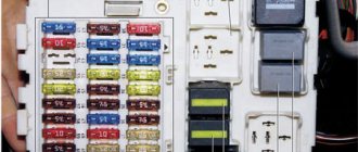
The main one is the fuse box near the engine. The vast majority of fusible protective elements and almost all relays are located here. During the existence of the model, its modifications changed several times. The most common modern block was presented in 2008. In this release, the arrangement of individual elements has changed slightly and new ones have been added.
You can find the block in the engine compartment above all the devices in the engine compartment. It is protected by a cover that can be easily opened by pressing two latches.
Diagnostics
After all additional work has been completed, you can proceed directly to diagnostics using a diagnostic scanner. In practice, it is easier to use a laptop with a diagnostic program installed instead. Before starting work, turn on the ignition. All work to assess the condition of the engine is carried out with the ignition on. Attention! It is forbidden to start the engine! We connect to the connector and launch the diagnostic program. Depending on its interface, you will first see either graphs with numbers or a list of indicators, again with numbers. From all this we can draw primary conclusions about the operation of the motor. Next, it “throws out” a list of detected errors. To decrypt them, you will have to look into the text file (usually it is downloaded along with the program). All errors that appear during engine operation are indicated there.
VAZ 2115 fuse diagram
The most common models are 3722010 (since 2004) and 21150 3722 010 10. The set of protective elements of electrical equipment in them is not very different from each other, but there are differences, and they are reflected in the decoding of the diagrams below.
The main mounting block under the hood of the car.
| Item no. | Power, A | What protects |
| 1 | 10 | Lamps for rear fog lights and PTF turn-on indicator |
| 1* | 10 | Headlight cleaner motor and relay (contacts). Headlight washer activation valve |
| 2 | 10 | Turn signals, breaker relay and hazard warning lamp |
| 3 | 7.5 | Interior lighting front, center, trunk Ignition switch Engine management system Brake lamps On-board computer |
| 3* | 7.5 | Rear lights (brake light) Body interior light |
| 4 | 20 | Cartridge for connecting a portable lamp Heated rear window (contacts) |
| 4* | 20 | Cigarette lighter Socket for portable lamp |
| 5 | 20 | Horn Cooling fan motor |
| 6 | 30 | Power windows Power relay (contacts) |
| 7 | 30 | Heater motor Windshield washer Headlight wiper motors (in operating mode) Cigarette lighter Glove compartment lamp Rear window heating relay (winding) |
| 7* | 30 | Headlight wiper motor Winding Heater motor Window washer Rear window wiper motor Windshield and rear window washer activation valve Cooling system fan activation Rear window heating relay coil Indicator lamp Glove compartment lighting |
| 8 | 7.5 | Right PTF |
| 8* | 7.5 | Left PTF |
| 9 | 7.5 | Left PTF |
| 9* | 7.5 | Right PTF |
| 10 | 7.5 | Left dimensions License plate lamps Engine compartment lamp Instrument lighting switch Illumination lamps for switches, instruments, cigarette lighter, ashtray, heater control levers Illumination panel for heater levers |
| 11 | 7.5 | Right dimensions |
| 12 | 7.5 | Right low headlight |
| 13 | 7.5 | Left |
| 14 | 7.5 | Left high beam headlight High beam indicator lamp |
| 15 | 7.5 | Right high beam |
| 16 | 15 | Turn signals, relay-breaker for turn signals and hazard warning lights (in turn signal mode) Reversing light lamps Lamp health monitoring relay On-board monitoring system display unit Instrument cluster Insufficient oil pressure lamp Parking brake activation lamp Brake fluid level lamp Battery low warning lamp Trip computer ( if installed) Generator field winding (in engine starting mode) |
| 17 | — | Reserve |
| 18 | — | Reserve |
| 19 | — | Reserve |
| 20 | — | Reserve |
Additional work
For more detailed diagnostics, inspect the car for body damage. Be sure to check the level of all technical fluids. Inspect the suspension and steering for any play. Compression must . Its values should range from 9.5 to 11 atmospheres.
In this case, the readings of all cylinders should be approximately the same. The significant difference between them serves as a reason to take a closer look at the motor. You also need to check the condition of the battery . The voltage should be about 12.7 - 13.5 V (it varies). As an additional check, it would be useful to check the valve adjustments. Clamping one or more valves will result in an engine power error. To avoid digging up the injector in vain, it is better to check the condition of the valves in advance. Check the functionality of the spark plugs and high-voltage coils (high-voltage coils).
Description of "brains"
The VAZ 2114 ECU is an on-board computer of the vehicle, designed to control the main systems of the car. The parameters of the control module affect both the functionality of certain regulators and the operation of the engine as a whole. That is, the importance of this system cannot be denied.
Controller Location
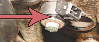
In VAZ 2114 and VAZ 2115 cars, the control module is installed under the center console of the car, in particular, in the middle, behind the panel with the radio. To get to the controller, you need to unscrew the latches on the side frame of the console. As for the connection, in Samar modifications with a one and a half liter engine, the mass of the ECU is taken from the power unit housing, from the fastening of the plugs located to the right of the cylinder head.
Location of the ECU in the Chetyrka
In cars equipped with 1.6- and 1.5-liter engines with a new type of ECU, the mass is taken from the welded stud. The pin itself is fixed on the metal body of the control panel near the floor tunnel, not far from the ashtray. During production, VAZ engineers, as a rule, do not securely fix this pin, so over time it can become loose, which will lead to the inoperability of some devices.
Design and principle of operation
The control unit of the electronic system operates in accordance with the indicators received from the sensors:
- speed;
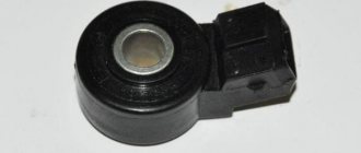
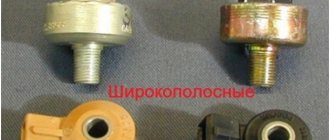
- detonation;
- lambda probe;
- fuel injection phases;
- crankshaft position;
- throttle position;
- air flow meter;
- antifreeze temperature.
In accordance with the data received from these controllers, the control module controls the following systems:
- ignition;
- adsorber;
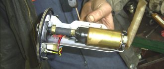
- injectors, as well as a fuel pump;
- ventilation and heating system;
- programs for diagnosing vehicle performance;
- idle speed regulator (video author - Evgeniy Vekhter).
As for the device, the control module structurally consists of the following components:
- RAM or random access memory. This module contains basic data about recently identified errors detected by the electronic system in the operation of various components. When the driver turns off the ignition, the RAM unit is updated, causing this data to disappear.
- PROM is the main element of the system; it contains the firmware of the control module. It should be noted that this memory block contains all the necessary data on the calibration of the “four” systems along with the general engine control algorithm. Unlike RAM, EPROM is a permanent memory, so the data stored in it is retained even after the ignition is turned off. If necessary, this module can be reconfigured, that is, reprogrammed, which can lead to improved power as well as vehicle dynamics.
- ERPZU - the primary function of this module is to protect the car. The EEPROM memory contains information from the anti-theft installation - passwords, as well as encoding of the main parameters. Starting the engine will only be possible if the EEPROM successfully checks with the data contained in the immobilizer memory.
Typical malfunctions: their symptoms and causes
What are the signs that indicate a faulty ECU:
- there are no control signals coming from actuators (IAC, flow meter, various sensors, etc.);
- there is no signal for interaction with the ignition system, fuel pump, injectors and other elements;
- when connecting a diagnostic tester, there will also be no connection with the electronic system;
- Burnt contacts and mechanical damage to the device may also be a sign.
What reasons contribute to the failure of the control device:
- electrical circuit shorted or broken;
- improper electrical repairs, during which errors were made, in particular, we are talking about installing or repairing an anti-theft system;
- lighting a dead battery from a car with the engine running;
- a breakdown of the unit can be caused by incorrect connection of the battery terminals - plus instead of minus and vice versa;
- disconnecting the battery contacts when the engine is running;
- moisture on the electronic system module board;
- mechanical damage to the device as a result of an accident (the author of the video about repairing the control module in a garage is the Auto Practice channel).
Two distributed injection systems with and without feedback
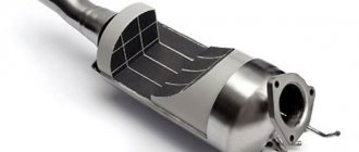
The feedback system is used mainly on export vehicles. It has a neutralizer and an oxygen sensor installed in the intake system, which provides feedback. The sensor monitors the oxygen concentration in the exhaust gases, and the electronic control unit uses its signals to maintain an air/fuel ratio that ensures the most efficient operation of the converter. Only unleaded gasoline should be used as fuel. The use of leaded gasoline will damage the converter, oxygen sensor and system failure.
In an injection system without feedback, a converter and an oxygen sensor are not installed, and a CO potentiometer is used to adjust the CO concentration in the exhaust gases. This system also does not use a gasoline vapor recovery system. The figure shows the design of this particular system, since it will mainly be used on cars sold in Russia.