If a car owner independently monitors the technical serviceability of his four-wheeled friend, then he must feel his car and know exactly where this or that element is located in order to quickly replace a component that has become unusable with a new one.
For example, the driver may notice the following:
- the furnace fan will start to work intermittently;
- The windshield wiper and glass heating either turn on normally or refuse to work;
- the engine started to have trouble starting.
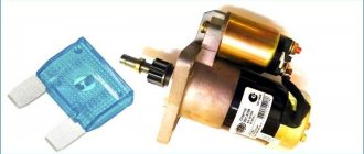
You should not immediately look for a breakdown in the starter or car module, because most often such a breakdown is caused by a starter relay that has become unusable. Experts do not recommend repairing such an element, since a failed element, even if it is thoroughly repaired, will very soon show signs of malfunction again, so the entire replacement operation will have to be repeated again. Replacing the so-called relay yourself is quite simple, but before doing this you should know exactly where the ignition relay is located on the VAZ-2114. We will deal with this issue, as well as with independent replacement of the “relay”, further in this article.
Operating principle
The VAZ 2114 ignition relay is structurally similar in design to other electronic relays.
Its main purpose is to start the starter and, as a result, initiate the start of the engine itself. At the same time, the relay is responsible for other equally important tasks, for example, for protecting the starter from too high voltage or, on the contrary, for starting the engine when the battery is dead (thus, it corrects the voltage in the power circuit going to the starter) .
In addition, by breaking the electrical circuit after starting the engine, the main relay thereby protects the ignition switch contacts from burning or even melting.
Location of the ignition relay VAZ 2114
No clicking of the solenoid relay
The absence of a click may indicate that either there is no voltage supplied to it, or there are problems with the pull-in winding. First of all, we check the wiring. To do this, visually inspect the positive wire going to the relay from the battery, and then the thin wire from the ignition switch. If possible, check the voltage level with a voltmeter (multimeter), connecting its positive probe to the terminal on the relay from which the wire goes to the battery, and the negative probe to ground. The device should show battery voltage. If this indicator is lower, you need to look for a problem in the wiring.
Interpretation of fuses and relays of injection models
The main electrical fuse module 2114-3722010-60 is located under the front engine compartment. This arrangement allows for quick access to all electrical systems of the car.
Block location
Please note that the location of the electrical fuse module may depend on the type of equipment and year of manufacture of the vehicle. As a rule, this is the upper right part of the engine compartment, under the front windshield. The mounting block is made of plastic in the form of a rectangular box. To protect against accidental opening, the box is equipped with special latches. To open the module, you need to snap off the two protective brackets and lift the top plastic protection. Under the cover are all the main control relays and electrical fuses of the vehicle.
To quickly remove the fuse, special plastic pliers are located on the plastic protection cover. With their help, you can very easily get any element. You need to grab the top edge of the plastic case with pliers and carefully lift the element.
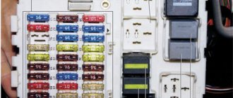
For the convenience of the user, on the top plastic cover there is a complete diagram, made in the form of a schematic image, which shows all the electrical fuses and relays indicating the current strength (A).
Fuse and relay diagram for injection models
Table 1. Explanation of fuses and relays 2114-3722010-60
| № | Current, A | Explanation of fuses |
| F1 | 10 | Rear fog lights, rear fog light indicator lamp |
| F2 | 10 | Turn signals and turn signal breaker relay. Alarm system. Hazard warning lamp |
| F3 | 7,5 | Interior and luggage compartment lighting systems (interior lamp, luggage compartment lamp, ignition key illumination). Brake brake lamp, on-board computer backlight lamp. Engine control lamp |
| F4 | 20 | Rear window heating control. Portable lamp connection socket |
| F5 | 20 | Relay for monitoring and turning on the sound signal. Cooling system engine switch fuse and relay |
| F6 | 30 | Control and relay switching on electric windows |
| F7 | 30 | Electric motor control - heating system, interior heater, windshield washers, headlight cleaners. Interior cigarette lighter, glove box lamp. Turn on the heated rear window. |
| F8 | 7,5 | Turning on the right fog lamp |
| F9 | 7,5 | Turning on the left fog light |
| F10 | 7,5 | Side light for the left side body, indicator light for turning on the side lights (on the display), lamps for illuminating the license plate and engine compartment, illumination lamp for switches, cigarette lighter, heater control levers. Instrument lighting switch. |
| F11 | 7,5 | Right side body marker light |
| F12 | 7,5 | Front right low beam headlight |
| F13 | 7,5 | Front left low beam headlight |
| F14 | 7,5 | Front left high beam headlight. Light indicator lamp. |
| F15 | 7,5 | Front right high beam lamp. |
| F16 | 15 | Body turn signals, relay-breaker for turn signals and hazard warning lights. Control relay and reverse lamps, indicator lamps for the on-board instrument control system, lamps for oil pressure, handbrake activation, brake fluid level, battery charge. On-board computer, engine generator winding. |
| F17-F20 | Spares | |
| № | Relay circuit | |
| K1 | Headlight cleaners | |
| K2 | Turn signals and hazard warning lights | |
| K3 | Windshield wiper | |
| K4 | Monitoring the serviceability of brake light lamps and side lamps | |
| K5 | Window lifters | |
| K6 | Sound signal | |
| K7 | Heated rear window | |
| K8 | High beam headlights | |
| K9 | Low beam headlights |
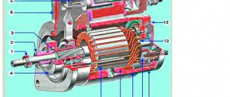
Starter wiring diagram
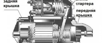
To understand the electrical part of the starter, let’s first get acquainted with its circuit and try to figure out how it works, what elements it consists of, what task the individual elements of the circuit perform.
The driver inserts the key into the ignition switch (6) and turns the key to start the process. Electric current from the battery (2) is sent to the generator (3) and to the solenoid relay mounted on the starter (1). When the generator is running, it begins to generate electricity and directs it to the tires of the mounting block (4), from where the current flows to the auxiliary starter relay and ignition switch. The relay closes the circuit and directs current to the coil of the solenoid relay, which in turn causes the starter to rotate using bendix. And he starts the engine.
Signs of a relay malfunction
Sure signs that the relay has failed may include:
- interruptions in the operation of the stove fan;
- problems with turning on the windshield wipers and heated windows;
- failures to start the engine.
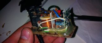
All these factors, and especially their combination, directly indicate that the device is broken and should be replaced. But before you begin the repair, you should find out where the ignition relay is located on the VAZ 2114? You should look for this electronic element under the decorative trim-casing, to the left of the steering wheel. In order to gain access to the relay, this casing must be removed.
In some cases, you can try to remove the relay without removing the casing. This can be done by carefully placing your hand underneath the casing. True, this method requires a certain skill and an accurate understanding of the location and method of attaching the relay. For this reason, when replacing the device for the first time, it is recommended to dismantle the casing.
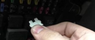
Ignition relay VAZ 2114 under a protective cover
Another, although less rare, but still common problem is overheating of the ignition relay. So, if after a long trip (during which many consumers were turned on, the operation of which is controlled by this relay - windshield wipers, glass heaters) it became very hot, then you should immediately begin searching for the cause, without waiting for the device to burn out or other problems in the on-board network.
As a rule, the high heating of the main relay is due to its low amperage in combination with a large number of consumers (the standard model 14 ignition relay is designed for a current of 70 Amps). In order to check this, it is enough to disconnect a number of devices from the relay (with the exception of the starter, of course) and check its condition after the trip.
If the relay remains cold, then the reason for overheating lies precisely in its low power. To solve this problem, you should install a new relay of a similar design, but designed for a higher current.
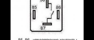
Ignition relay contacts
Starter, ignition, rear fog lamp relay
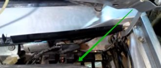
In order to carry out quick checks and repairs, the ignition system relay is installed under the front dashboard of the car, behind the hood release handle. It is located just below the central dashboard. The module is closed with a plastic plug, which must be opened slightly to test for functionality.
Starter, ignition, rear fog lamp relay
Next to the indicated relay, there is a similar one for the rear fog lights and the starter.
The main task of the relay when igniting is to reduce the applied load to the contacts. When the engine starts, the relay turns off some electrical circuits in the vehicle system. The system is used not only in injection, but also in carburetor engines.
In the event of a malfunction or malfunction in the ignition system, it is necessary to monitor the operation of the relay. For this purpose, open the box and carefully remove the desired element. It is attached using contacts to special grooves. The first thing to do is look at the oxidation of the contacts, if necessary, clean them with a soft cloth or treat them with a special liquid.
To check functionality, you need to use a regular multimeter. We connect to incoming connections and check the numbers. If there is no short circuit when current is applied, it means the element is not working. Replacement is carried out in a similar manner. It is necessary to use a standard element with the number of amperes indicated on the housing.
Where is the VAZ-2114 ignition relay located: photo diagram and video
Even before buying a car, I heard about problems with electrical systems in Samara. So I had to face this myself.
Since I’m not much of an electrician or mechanic, I still started digging for information on the Internet. At the beginning of winter, as always happens, the heater fan and the rear window heating stopped working when the ignition was on (everything worked when the ignition was off). In winter, it’s simply not possible to drive without a heater, or you can, but like in a tank, with a scraper in your hand. I started digging for information on this part. I didn’t find anything intelligible, but even then I began to blame the contact group of the ignition switch or something connected with it, since the F7 20 A fuse was in order, the mounting block also became in order after removing it, cleaning and drying it in the fall (gifts from The previous owner removed the fire pit by covering it with half a 5 liter plastic bottle) and visually did not find any jambs in the wiring.
I removed and connected the black box, again not without swearing. Well, why couldn’t AvtoVAZ engineers make the wiring with chips 5 cm longer? Did you spare the wires or what?
I had no experience in replacing or reassembling the lock, it was winter, so in short I didn’t go there.
I drove in the winter, you won’t believe it!)) On the handbrake. Since the alarm is on autostart, the handbrake is not tightened, and the car does not stall when the ignition is off, but the heater was working)))
I could have driven like this for another month until it warmed up, but then this heater shut down completely (if it weren’t okay, as my great-grandmother said), even with the handbrake, taking with it the windshield washers, the rear wiper, and the rear heating. glass, and lighting for the junk drawer, in short, it looks like everything that hung on the F7. The wipers continued to work. I looked at fuse F7, which is intact. I started digging for information again.
Most of the advice focused on the ignition switch unloading relay at best and on the wiring, mounting block and short circuit at worst. I decided to start with the easiest one. It turned out that the ignition switch had nothing to do with it at all. Some electricians advised, like buy a new one and don’t worry about rebuilding the old one. Moreover, it would still have to be removed in order to buy a similar one from the 10... But I show promise as an inquisitive car owner and decided not to spend money on it until I find out everything and look at the condition of its contact group.
Anyway, I bought a relay, it costs 38 rubles. He crawled under the steering wheel with a flashlight in his teeth, legs up. Again, not without swearing and strong language. Some advice was to move it first, wake up the relay without replacing it after identification, throw it off - put on the chip and tighten the nut on the stud. (well, it’s very uncomfortable there because). The one with it also has the rear fog light relay attached. Tightened it, moved it, everything worked. And you no longer need to drive with a handbrake. No replacement needed!
Actually, why did I write all this down? In principle, there is information on the Internet and on the website, but in some places there are no photos, or it is not clear where the relay is, in others there are no symptoms of the disease. I decided to have everything in one place.
I would be glad and grateful if someone read to the end and this material will be useful to someone.
Comments 11
Explain, as someone who has already figured it out, to someone starting to figure it out: does this relay generally remove the load from the lock? That is, if it fails, can any part that is powered by the lock fail, or just the part that failed in yours? It’s just that the symptoms are similar to yours, but my fuel pump still refuses to pump today...
Look on the net for what this feature is responsible for, what hangs on it, I saw it somewhere on the drive. As far as I know, there isn't much hanging on it. What exactly is your problem, please elaborate?
Even if I didn’t get it, why would I turn off the ignition? Start it and drive) Well, what are the problems with the stove? Naturally, when the engine is turned off, it will not heat up, since the coolant heats up as it passes through the system... I’m still at a loss)))
I answer, the stove stopped working when the ignition was on and the car was running, so that I wouldn’t freeze in the winter, I drove with the ignition off))) the car has an alarm with autostart Starline A91, you start it, lift the handbrake, turn off the ignition - the car won’t stall until there’s a button on the key fob press. That's how it's set up. I myself did not immediately guess about this, at first glance, stupid solution to the problem)) You have to drive the right way))
- Editing history
no, well, I know this feature, I saw it once on one 14k))) on mine, I pressed the button, the locks closed and that’s it)) everything is simple and disgraceful))) but I don’t even understand about the stove, I just didn’t get into it in its deep technical part, but there doesn’t seem to be anything electronic there, you move the regulator and a faucet opens a flow of hot coolant through the heater radiator) recently, by the way, I had to change this faucet, the passenger side was filled with antifreeze up to the tomatoes! I was cursing when my dad and I were changing this miracle mechanism, they remembered all the AvtoVAZ engineers))))
Yes, there is no special electronics on the stove, the resistor is only for the regulator, ala AvtoVAZ climate control, either it blows in the face or in the legs, there is no third option)) the relay somehow influenced the entire circuit of fuse F7. (heater, washer, rear wiper , heated rear window).
well, a fan, I think)))
Idiot question, how did you manage to drive with the handbrake?
))) I bought a car and needed to tighten the handbrake (I think not on the cable but on the rear pads) but due to the circumstances described, I did not repair it))) How did you drive? Started it up, raised the handbrake, turned off the ignition)
So they write that disc brakes hold the handbrake perfectly, but they don’t work for long.
Materials: https://www.drive2.com/l/3427414/
see also
Comments 133
Hello, I have a VAZ 2114. The plus on the ignition module has disappeared, where would you recommend dropping the engine control relay? I changed the fuses in order. When I turn the key, the switches click, but there is no plus on the ignition module.
Contact an electrician
Greetings. I have a VAZ 21120. The problem here is that I started the engine, turn it off, but it does not stall, I took out the key, but the engine and the tidy are working, turn it off by paying attention to the main relay. At the same time, I put a new relay on 30a, nothing changes, I put a relay from Ford on 40a, everything works in normal, normal mode, but the engine does not start. What could this be, please tell me
Good day, friends! Greetings from Kazakhstan! The problem is the cooling fan not working. I changed the temperature sensor, removed the fan sensor chip, it was in the way. I assembled everything, and when the highest temperature is reached, I wait for the fan to turn on. It won't turn on. I had to resort to forcibly turning on the fan by disconnecting the sensor chip. The car is a VAZ 2114. If you had such a problem, please share. C/u Timur. I will be immensely grateful.
If there is no signal sent to the engine coolant radiator fan, then it is either the coolant sensor, or the fan relay, or a fuse, or the ECU does not give a turn-on signal. IMHO.
Good day, can you tell me what I might have a VAZ 2114, a week ago the car sat for a day and wouldn’t start, after 2 days I decided to try to start it - it started as if nothing had happened, I drove for a week, the same situation, the car didn’t start for a day again won’t start, the fuel pump is fine It buzzes, the starter turns but there is no spark... I drove it every day. Dampness and rain outside, but what does this affect? Maybe they sent me a relay to see what else it could be?
Good afternoon I have a VAZ 2114. When accelerating sharply, the car accelerates too quickly, then stops, and the traction disappears. I stop, the speed freezes at 2000 rpm, and does not drop. Who had this problem? Please tell me. I will be immensely grateful. Best regards, Timur.
Do they drop when you turn off the ignition?
Yes. The car stalls with a shudder. When restarted it will start.
I would check the timing marks first.
Timing marks? I didn't think so. Thanks Pavel. I'll check and write an answer.
I had something similar on the 2114. It turned out that the generator pulley on the crankshaft had shifted a little, cutting off the pin.
That's it. I'm okay with this. Following your advice, I turned the crankshaft. The belt fell off by two teeth. Thank you very much. The check did not go out, I think there was some kind of error. But the engine began to run smoother.
Do they drop when you turn off the ignition?
The revs fluctuate a little and it stays fine.
I would reset the battery terminal for a few minutes. Then I would check the VUT valve and the VUT hose.
I will definitely do it. But explain what VUT is.
I would reset the battery terminal for a few minutes. Then I would check the VUT valve and the VUT hose.
Isn't this a vacuum cleaner?
I would reset the battery terminal for a few minutes. Then I would check the VUT valve and the VUT hose.
How to identify a malfunction
To determine which fuse needs to be changed, look at the block cover. It contains symbols of the electrical circuit elements; choose the fuse that corresponds to the non-working element of the VAZ 2114. Replacing the PP is also not difficult. You have already opened the hood, found the power supply unit, and were able to open it (by unlatching the latches on the sides of the unit). Now take tweezers and pull out the burnt fuse and install a new one in its place.
Important! If any fuse fails, it is important to replace it with an identical one, no more or less current.
There are two ways to find out that an element has burned out. Firstly, visually. If its middle part is intact, it is intact; if it is burnt (black, melted, etc.) then it’s time to replace it. Secondly, use a multimeter to measure the voltage at the ends of the PCB. To do this, start the car, close the circuit, that is, turn on the device that is faulty, and measure the voltage at the ends of the PP. If a fuse element burns out, there will be voltage at one end and not at the other.
Explanation of the additional fuse and relay block
To turn on the main systems of any car, the manufacturer has designed the installation of auxiliary fuses. As a rule, they are located in the center console area. Each auxiliary module consists of several important relays and fuses.
In this particular case, the box is located to the left of the glove compartment, behind the side trim of the center console. To quickly access the box, you need to remove part of the plastic protection. The protection is attached to Phillips bolts, so you need to prepare the appropriate screwdriver.
Location of the additional fuse and relay box 2114, 2115, 2113Additional unit in the passenger compartmentDiagram of the additional unit
Table 3. Explanation of the additional fuse and relay block
Replacing the block
There are malfunctions in which car enthusiasts have to dismantle the mounting block to check it. These malfunctions are associated with the following reasons:
To remove the power supply, you need to remove its cover (you can read how to do this above), disconnect all the wires from it. Further, if the unit is completely faulty, it can be easily removed and a new one installed by reassembling it in the reverse order.
Advice! When disconnecting, be sure to mark the wires so as not to forget what to connect and where when reassembling.
We have discussed how to diagnose problems with PPs and relays, now let’s see how to identify problems with conductive paths and contacts:
- Even an experienced electrician has a hard time identifying this type of damage. Even if the problem is identified, soldering has to be done with very high precision, which requires high qualifications and a lot of time;
- The main problems associated with contacts in the VAZ 2114 power supply arise due to corrosion and contamination of the contacts. You can usually just clean up the contact with a knife or sandpaper. If it breaks off, you can solder it, but this is very labor-intensive and difficult; one wrong move and replacing the block cannot be avoided.
It’s always better to see once, so look at this review of the VAZ 2114 fuse box:
Operating principle, design and characteristics of fuses
The principle of operation of fuse links is deciphered by their name. Fuses are made of low-fusible conductors that can withstand a certain amperage. Depending on the purpose and voltage of the circuit being served, fuses are divided according to the current strength they can withstand. Typically, VAZ 2114 uses inserts from 5 to 30 Amperes.
Purpose of fuses
The main purpose of the fuse is to protect devices and equipment from overloads and short circuits. If the maximum limit is exceeded (short circuit inside the wiring circuit), the part is destroyed, which leads to an open line. Consequently, the part remains undamaged.
Common faults
Among the frequent calls to the service station are:
- wiring burnout;
- water entering the contacts and, as a result, closing them;
- damage to wires;
- malfunctions of electronic units.
With rare exceptions, the fuse box itself breaks down.
Checking and replacing fuses and block
To check the fuse for serviceability, remove it from the socket and visually inspect it. If the part is intact, there will be no soot or traces of oxidation on it. Direct replacement is carried out using the pliers included in the kit. It is strictly forbidden to pull out the inserts by loosening them - you can break the legs.
Repairing the block is getting more complicated. Here you will need to perform the following sequence of actions:
- open the mounting panel cover;
- find and unscrew the 4 mounting screws;
- Carefully lift the module and disconnect the terminal blocks.
It is important to exercise extreme caution when performing the procedure - the part can be easily damaged.
This is interesting: How to remove the abs error
How to check the operation of the fuel pump?
First, you should check the fuse. To do this, check the instructions for its location. Next, you should check the voltage at the pump. Before doing this, be sure to check if everything is in order with the battery. The voltage at the fuel pump terminal must be checked using a multimeter or tester. The instruction manual always indicates the required voltage.
Using a tester, check the voltage supply to the fuse. Often this is where the electrical circuit breaks.
If the search does not yield results, then the voltage should be checked on the contacts themselves. All contacts must be in place and connected to ground. A broken contact or its oxidation leads to failure of the fuel pump system. If no broken contacts are detected, but the voltage drops by more than 1 volt, then the problem is in the wiring or oxidation of the contacts. There should be no short circuit in the wiring.
If, after checking the voltage, contacts and fuse, you do not find any problems, then the problem lies in the fuel pump itself. In this case, the fuel pump will most likely require replacement. In practice, it most often turns out that replacement is a last resort. First, you should try to restore and test the fuel pump again.
Before you check the fuel pump, you need to remember that, as mentioned above, pressure is the most important characteristic of the fuel pump, so it is worth measuring its level.
How to check the pressure in the fuel rail?
You will need a pressure gauge that measures pressure in the range from 7 to 10 atmospheres. If you choose a pressure gauge with a large margin, you risk getting less accurate measurement results. Specialized stores sell a kit for measuring pressure, but you can also design your own device.
If you want to assemble the device yourself, you will also need a hose with an internal diameter of 9 millimeters. You will also need plumbing tow, with which you can seal the connection between the pressure gauge and the tube. All parts are connected and tightened using a clamp. You will also need a car spool. Next you need to perform a series of actions:
- Place the car on a level surface that is prevented from rolling, turn off the ignition and open the hood.
- Check that the injection nozzles have access to the fuel rail.
- Find the fuel pressure plug and remove it. Then you should unscrew the nipple using the spool.
- Prepare an empty container (a regular bucket will do) and a clean rag. This is necessary to collect residual fuel, which under pressure can splash out in different directions. Therefore, take care of the safety of your skin (especially your face and eyes).
- Connect the device to the fitting and begin checking the mechanism.
Checking the pressure in the fuel rail should occur in four operating modes of the power unit:
- when the ignition is on;
- at idle engine speed;
- code the fuel pressure regulator tube is reset;
- when the drain tube is compressed.
Fuel rail pressure measurement results
The results may vary slightly for different car models, but in general they should be as follows:
- when the ignition is turned on, the pressure must be at least 3 atmospheres,
- at idle engine speed - at least 2.5 atmospheres,
- when the pressure regulator tube is reset - at least 3.3 atmospheres,
- when squeezing the drain tube - at least 7 atmospheres.
Fuel rail pressure fluctuates slightly during preparation. When you press the pedal, it suddenly takes on a value of 3 atmospheres; when you release the pedal, it drops to 2.5 atmospheres. When fuel enters the fuel system, turn off the ignition and begin observing the pressure gauge. The pressure in this case should drop to 0.7 bar and remain unchanged.
If the pressure drops to zero, there may be a problem with the fuel pressure regulator. In this case, the regulator must be replaced immediately. The cause could also be the fuel pump check valve.
It is necessary to observe the behavior of the pressure gauge even at 3,000 engine speeds. A drop in pressure will indicate a faulty fuel pump. Sometimes the fuel pump cannot reach the required pressure for a long time. In this case, the problem lies in a clogged fuel filter, which needs to be replaced, or in a dirty fuel pump mesh (read more about where the fuel filter is located).
If the above methods do not reveal a malfunction of the fuel pump, you will have to diagnose other units (DPZD, IAC, mass air flow sensor, compression in the engine and some other indicators and parts).