Some car owners ask search engines where the VAZ 2114 starter fuse is located, but they do not find an answer, because the VAZ 2114 and earlier models of cars from this manufacturer do not have a starter fuse. On several sites, in response to requests for the location of the fuse, huge reviews have been written about the mounting block, but they also do not essentially answer the question posed, because there is no fuse in the mounting block .
The protective function is assigned to the auxiliary relay - a compact device that is located under the steering wheel next to the hood release handle.
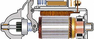
How it works
The device works as follows:
- The battery supplies power to the starter coil;
- The coil acts on the armature due to the influence of the magnetic floor;
- The armature moves and compresses the return spring;
- This causes the bendix to mate with the splines located on the flywheel;
- When the contact elements close, the pull-in winding is deprived of power, and the armature is held inside the system due to the magnetic field;
- After closing the contacts and starting the engine, power stops going to the holder coil, and the armature returns to its place due to the action of the spring. As a result, the bendix disengages.
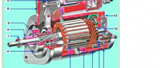
Operating principle
When the ignition is turned off, the armature, thanks to the spring, is in the extended position. The Bendix gear, however, is not engaged with the flywheel crown. When we turn the ignition key to the second position, voltage is applied to the relay contacts. The magnetic field created by the retractor coil drives the armature. It moves backward, compressing the spring, and closes the contacts through which voltage is supplied to the starter. The retracting winding is turned off at this moment, and the holding winding is turned on.
During movement, the armature moves the fork along the rotor shaft. She, in turn, moves the bendix, bringing the gear into engagement with the flywheel. When we release the ignition key, the voltage on the holding coil stops flowing, and the armature returns to its original position under the influence of the spring. The fork, at the same time, disconnects the Bendix gear and the flywheel crown.
Malfunctions and their symptoms
If you visually inspect the relay when it malfunctions, you may notice stuck contacts, traces of charring on the wiring, burnt windings, and signs of wear.
But it is not at all necessary to disassemble the assembly to recognize the signs of a faulty solenoid relay. They look like this:
- The engine runs, but the starter still turns. At the same time, the sound is too loud and uncharacteristic;
- When the ignition is turned on, the starter does not spin, although the relay makes a characteristic click;
- The ignition is turned on, but the starter is idling and the engine does not respond.
All this suggests that there is a high probability of your transmission on the VAZ 2114 breaking. Therefore, it must be removed and a new element installed in place of the damaged one.
Installation process
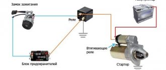
- We prepare the wiring. We crimp the connectors.
- The new VAZ 2110 starter relay must be mounted under the hood in a place so that it is definitely not flooded with water from puddles and rain. Many specialists install the relay on the stud of the washer reservoir.
- We bring the wire from the relay to the starter and connect it to the place of the red wire (it is with the “dad”). This is the connection point for the traction relay. This way we energized the coil of the new relay.
- We put a new wire with an 8 (mm) ring connector onto the positive terminal of the starter and tighten it tightly with a bolt. This wire goes to pin 87 in the new relay. I hope the VAZ 2110 starter connection diagram is clear to everyone.
- From the new relay on pin 30 we pull a wire with a “female” connector to the starter, to the place where the traction relay is connected.
- We connect the lead from pin 85 on the new relay to ground.
- We cover all wiring with a corrugated sleeve and thoroughly insulate it so that the wiring and contacts are not exposed to moisture.
- We do a test drive.
That's it, the additional VAZ 2110 starter relay (diagram attached) has been successfully installed.
Where is the starter fuse located on the VAZ 2114?
As already mentioned, there is no fuse on the VAZ 2114 starter. Perhaps the error was caused by connecting the starter through the mounting block. But this device serves as a kind of distributor, a conductor of electric current with low resistance through the busbars. The second reason that forces car owners to look for where the starter fuse is located on the VAZ 2114 is the information that the Priora has such a fuse. And it, together with the auxiliary relay, is located in the mounting block, which, unlike the VAZ Samara.
Pinout of mounting block 2113, 2114, 2115
Diagram of the VAZ-2113, 2114, 2115 mounting block Option No. 1.
K1–relay for turning on headlight cleaners; K2–relay-interrupter for direction indicators and hazard warning lights; K3 – windshield wiper relay; K4 – lamp health monitoring relay; K5 – power window relay; K6 – relay for turning on sound signals; K7 – rear window heating relay; K8 – headlight high beam relay; K9 – relay for turning on low beam headlights;
Diagram of the VAZ-2113, 2114, 2115 mounting block Option No. 2.
Numbering of plugs in the connecting blocks of the VAZ 2113, 2114, 2115 mounting block
New model mounting block VAZ-2113, 2114, 2115. Location of fuses and relays.
K1–relay for turning on headlight cleaners; K2–relay-interrupter for direction indicators and hazard warning lights; K3 – windshield wiper relay; K4 – lamp health monitoring relay; K5 – power window relay; K6 – relay for turning on sound signals; K7 – rear window heating relay; K8 – headlight high beam relay; K9 – relay for turning on low beam headlights; F1–F20—fuses; X11 – terminals of the wiring harness block
Table of circuits protected by fuses on the VAZ 2114
| Fuse number | Current strength, A | Circuits protected by a fuse |
| F1 | 20 | Rear fog lamp switching relay. Rear fog lamp lamps. Rear fog lamp switching indicator |
| F2 | 10 | Direction indicators, relay-interrupter of direction indicators and hazard warning lights (in hazard warning mode) Hazard warning lamp |
| F3 | 7.5 | Front interior lamp. Central interior lamp. Luggage compartment lighting. Illumination lamp for the ignition switch. Lamp for monitoring the engine management system. Brake light bulbs. Trip computer (if installed) |
| F4 | 20 | Socket for connecting a portable lamp. Relay for turning on the heated rear window (contacts). Rear window heating element |
| F5 | 20 | Sound signal. Horn relay. Cooling fan electric motor. Fan fuse. |
| F6 | 30 | Electric windows. Power window relay (contacts) |
| F7 | 30 | Heater electric motor. Heater fuse for VAZ 2114, VAZ 2115. Electric motor for windshield washer. Headlight wiper motors (in operating mode) Cigarette lighter fuse. Glove box lighting lamp. Rear window heating relay (winding) |
| F8 | 7.5 | Fuse for fog lamps VAZ 2114, 2115 - Right fog lamp |
| F9 | 7.5 | Fuse for fog lamps VAZ 2114, 2115 - Left fog lamp |
| F10 | 7.5 | Side light lamps on the left side. Indicator lamp for turning on the side light. License plate lamps. Engine compartment lamp Instrument lighting switch. Fuse for backlight lamps of switches, instruments, cigarette lighter, ashtray, heater control levers |
| F11 | 7,5 | Side light lamps on starboard side |
| F12 | 7,5 | Right headlight (low beam) |
| F13 | 7,5 | Left headlight (low beam) |
| F14 | 7,5 | Left headlight (high beam). High beam indicator lamp |
| F15 | 7,5 | Right headlight (high beam) |
| F16 | 15 | Direction indicators, relay-interrupter for direction indicators and hazard warning lights (in turn indication mode). Reversing lamps. Relay for monitoring the health of lamps. On-board control system display unit. Instrument cluster. Insufficient oil pressure indicator lamp. Parking brake indicator lamp (brake light fuse). Brake fluid level indicator lamp. Low battery indicator lamp. Trip computer (if installed). Generator excitation winding (in engine starting mode). Front windshield wiper. Seat heating control. |
Sources
- 2shemi.ru/raspinovka-montazhnyh-blokov-avtomobilej-vaz
- ladaautos.ru/vaz-2115/opisanie-montazhnogo-bloka-vaz-2115.html
- galantmotors.ru/document/shema/2114/2114_rele_predohraniteli.php
- drive2.ru/l/5419303/
Where is the starter relay located on the VAZ 2114?
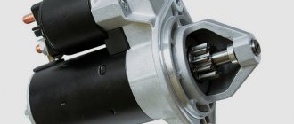
The VAZ 2114 starter has two relays. The first is a retractor; it is mounted together with the starter in one housing. The second relay is an auxiliary one. Sometimes it is mistakenly called unloading. This relay is located under the instrument panel, next to the ignition relay and rear fog light relay. This little relyushka spoiled the blood of more than one car owner who was unaware of its existence. A four-contact relay, forced to withstand a serious load every time the car is started, fails quite often, and it is useless to repair it. It's better to change it right away. When this relay fails, the starter will no longer turn. In response to turning the key, only dry clicks are heard.
How to make a start button instead of an ignition key in a car with your own hands
In older cars, often the wires from the starter itself are connected directly to contacts inside the contact group, which close when the ignition key is turned. When the starter is activated, a very large amount of energy is consumed, which means a large current flows (the contacts strike a spark). Over time, a burnt deposit forms on the contacts or they completely burn out, no longer providing reliable contact. Newer vehicles have a separate relay that closes the starter contacts when the ignition key is turned.
The main advantages of using a relay in the starter power circuit:
- Such a system is more reliable, since the relay is designed for high currents and lives much longer. - The relay can always be replaced - The contact group behind the ignition key works for a very long time, since it turns on only the relay that takes the main load.
Regardless of whether your starter is turned on by a relay or directly by a contact group, all operations to connect the starter are still performed by turning the key.
First you need to determine which contacts are responsible for the start and connect them to the start button.
To do this, you need to disassemble the plastic protection under the steering wheel of your car. Very often, a connector with all the necessary wires is connected to the contact group of the key well at the back. There should be locking tabs on both sides of this connector. You need to press on them and pull out the connector.
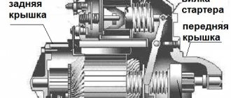
Dismantling and replacement
To make it more convenient to replace the relay, it is recommended not to be lazy and still remove the starter itself. This will allow you to simultaneously check the condition of the starter while replacing the relay.
First, disconnect the negative terminal from the battery. Otherwise, you will be seriously shocked. There is little pleasure in this. Plus, this will lead to burnout of the wiring, which will be extremely difficult and time consuming to change.
The removal procedure described below concerns an assembled relay, which has the ability to replace individual structural elements.
- Disconnect the negative terminal from the battery.
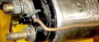
- Disconnect the red terminal from the relay. This is a red wire.
- Using an 8 mm wrench, unscrew the nut securing the brush assembly. You will find it behind the relay.
- Remove the contact that this nut held in place.
- Unscrew the fastening of the solenoid relay to ground. We are talking about coupling bolts.
- Next, you need to dismantle the power wire, after which the relay itself is pulled out.
- The fastening nuts are unscrewed from the end part, which allows you to remove the upper part of the relay.
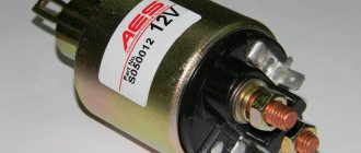
- It is advisable to immediately replace the relay core with a new one.
- Install a new relay.
- Proceeding strictly in reverse order, reassemble the assembly, which will allow you to complete the replacement of the unit.
- When separating the relay into its two component parts, be sure to ensure that the core does not slip out and the spring does not jump out.
We can say that replacing the gearbox on a VAZ 2114 is not so difficult. It is much easier to replace a non-separable relay, since to replace it it is enough to unscrew all the fasteners in the same way and disconnect the contacts.
Electrical diagram of VAZ 2115
Such models are marked with the numbers F2 10A Direction indicators, relay-breaker for direction indicators and hazard warning lights in hazard warning mode. Then release the pressure, turn off the power to the fuel pump and turn on the ignition. In some cases, the problem in the operation of certain devices is solved by reconnecting the plug if it is a question of poor contact of the device with the electrical network. Lift the pump assembly and pull out the electrically powered fuel pump. It has an anti-theft device. In this case, the blocks “12” are connected to the washer pump, and the wires connected to the pumps “13” and “14” are connected to the corresponding solenoid valves.
As a result of the change in the circuit, changes were made to the design of some electrical circuits. Table 7. Distributive fuel injection systems are controlled electronically.
Using a screwdriver, unscrew the 2 screws that fit the fuel lock and pull it out. Learning to read a car's electrical diagram. Part 1. Auto electrics.
Checking work
Sometimes, despite more than obvious signs of breakage or wear of the retractor, in reality everything turns out to be wrong. The car may behave similarly with some other malfunctions.
Therefore, in order to figure out whether the relay works or not, and also who is the real culprit for the violation of the functionality of the system, we will conduct several checks.
- Check the starter. Turn the ignition key. The starter should begin to turn, and the relay should make a characteristic click. If the starter is not doing its job, replace it. Relyukha has nothing to do with it in this case.
- Check the solenoid relay. To do this, there are two copper bolts on the back cover. Two contacts are attached to them. If the starter starts turning, then your relay has definitely failed and needs to be replaced. In this case, you should not remove the starter, which will allow you to get more accurate test results.
- If you have removed the starter, the check is performed slightly differently : Connect the contact wire of the retractor relay to the positive terminal of the battery;
- The second contact connects the starter ground and the battery charger;
- When the contacts are placed on the relay terminals, the relay should turn on with a characteristic click;
- If the operation is too slow, uncharacteristic, check the condition of the contacts. They often burn out or oxidize.
Engine control circuit (January 5.1, Bosch M1.5.4N)
- Fragment of the mounting block;
- Electric engine cooling fan;
- Automotive anti-theft system status indicator;
- Automotive anti-theft system control unit;
- Coolant temperature sensor;
- Air flow sensor;
- Throttle pipe;
- Block connected to the throttle position sensor;
- Block attached to the idle speed control;
- Controller;
- A block connected to the air conditioner wiring harness;
- Oxygen sensor;
- Knock sensor;
- Crankshaft position sensor;
- Speed sensor;
- Adsorber;
- Accumulator battery;
- Main relay;
- A block connected to the anti-lock brake system wiring harness;
- Diagnostic block;
- Main relay circuit protection fuse;
- Controller protection fuse;
- Fuse for protecting the electric fuel pump and its relay;
- Relay for turning on the electric fuel pump;
- Electric fan switch relay;
- A block connected to the instrument panel wiring harness;
- A block connected to the instrument panel wiring harness;
- Ignition module;
- Electric fuel pump with fuel level sensor;
- Spark plug;
- Injectors;
- F — Front harness wire going to the “B+” terminal of the generator;
- G - Front wiring harness wires.
The order of conditional numbering of plugs in blocks:
- A - Controller;
- B — Control unit of the automobile anti-theft system;
- B — Indicator of the status of the automobile anti-theft system;
- G - Pads 26;
- D - Throttle pipe;
- E - Air flow sensor;
- F - Electric fuel pump and oxygen sensor;
- 3 — Speed sensor;
- And - Ignition module.
Purpose of plugs in block 26:
- To the low-voltage tachometer input in the instrument cluster;
- —
- To the engine management system control lamp in the instrument cluster (from the controller);
- To the dome light switch located on the driver's door pillar;
- To the engine control system control lamp in the instrument cluster (+ power supply);
- To the trip computer (fuel consumption signal);
- To the instrument cluster (vehicle speed signal);
- To terminal “15” of the ignition switch (plug 4 of the switch block).
Differences between starter and relay failure
In order not to confuse what exactly has failed - the starter or the solenoid relay, there is an excellent method for recognizing the “culprit”.
- Remove the starter, connect the negative terminal of the battery to ground;
- The design of the device has copper bolts and a tongue-shaped element;
- The positive wire from the battery is connected to this “tongue”;
- If there is contact, the solenoid relay clicks and starts working;
- If not, then you will have to go to the store for a new relay.
The performance of the starter can be checked differently. To do this, the negative wire from the battery is attached to the starter ground, and the positive wire is attached to a bolt (contact goes from it to the solenoid relay). If the starter starts turning, then everything is fine. Your hypothesis about the problem relay was once again confirmed. Just before checking, make sure that the contacts themselves are in good condition and not damaged. Many people forget about this, which leads to incorrect conclusions regarding the performance of the two elements.
But there is one more very important point. Even if all the facts indicate that the starter or retractor relay is not working, another unit - the ignition switch - may still be the cause of ignition problems. Take the time to check its serviceability before buying new parts.
Preliminary safety notes
- Voltage above 36 volts is considered dangerous to humans. Electric shock of 0.1 ampere is fatal. The situation is aggravated by high humidity and metal flooring.
- The starter is a DC electric motor capable of delivering 260 amps at maximum load.
- Interfering with bare hands or metal tools into the current circuits of a switched-on unit is dangerous to health. Dismantling, repairs, and installation must be performed with the battery power turned off.
- Testing windings for interturn short circuit and insulation breakdown to ground is performed with a megger. The generator of the measuring device produces voltage up to 2500 volts. It is prohibited to touch the contacts during the verification process.
- Electric motor equipment requires care and experience. Printed and electronic publications are not deprived of the right to errors or typos. An incorrect wrench size will quickly become apparent. A play on Russian words will sound, untranslatable into foreign languages. Things will go further. The inaccuracy of the diagram is hardly noticeable.
- At the first symptoms of uncertainty or lack of knowledge, you should contact a professional auto electrician. The safety of car wiring and on-board electronics is valued above personal ambitions.
Some useful tips
To ensure that the solenoid relay lasts as long as possible, listen to these tips:
- If the battery is discharged, the starter turns slowly and its speed is not enough to start the engine, stop trying to start the car. This will not only cause the battery to become deeply discharged, but also damage the starter relay.
- When starting the engine, do not turn on the starter for more than 15 seconds. This will lead to an overload in its circuit, due to which the relay contacts may burn out, its windings and the starter windings may burn out.
- When choosing a replacement solenoid relay, do not buy cheap products. It is better to give preference to parts from well-known manufacturers, and buy them only in specialized stores.
There is a click, but the starter does not turn
If you clearly hear the relay click when you turn on the ignition, the problem is most likely in the starter itself. Perhaps the brushes are worn out, or there is a break in one of the windings. In any case, further diagnostics without dismantling the device is impossible. If a break in the windings is detected, you can try to restore the starting device by entrusting it to winding winding specialists. If things are generally bad with it, it is better to buy a new starter 2114. The price for it varies between 3700-5000 rubles.