The speed sensor is an element of the vehicle's electronic control system.
It depends on its readings how much fuel will be supplied, how much air will bypass the throttle valve when idling, and what the speedometer readings will be. The speed sensor of a VAZ car is based on the use of the Hall effect, that is, a stream of pulses is transmitted from the device to the car's ECU, the frequency of which is proportional to the speed of the car. Auto electronics, analyzing incoming data, selects the required idle speed and sends a signal to a device that regulates the engine idle speed, which optimizes the composition of the air-droplet mixture entering the combustion chamber, bypassing the throttle valve.
During a distance of one kilometer, the speed sensor transmits over 6000 pulses to the ECU. Based on the parameters of the time analysis of inter-pulse signals, the on-board computer transmits data to the dashboard, thereby determining the speedometer readings.
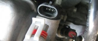
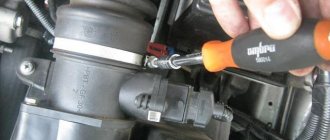
As in many other cars, the VAZ speed sensor is located in the upper part of the gearbox housing, not far from the engine oil level dipstick. You can get to it from two sides: from above, by opening the hood and disconnecting the adsorber, and from below, using the inspection hole for convenience.
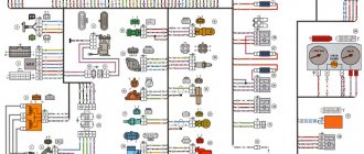
VAZ speed sensor pinout and DS connection diagram
The speed sensor is an element of the vehicle's electronic control system. It depends on its readings how much fuel will be supplied, how much air will bypass the throttle valve when idling, and what the speedometer readings will be.
The speed sensor of a VAZ car is based on the use of the Hall effect, that is, a stream of pulses is transmitted from the device to the car's ECU, the frequency of which is proportional to the speed of the car. Auto electronics, analyzing incoming data, selects the required idle speed and sends a signal to a device that regulates the engine idle speed, which optimizes the composition of the air-droplet mixture entering the combustion chamber, bypassing the throttle valve.
During a distance of one kilometer, the speed sensor transmits over 6000 pulses to the ECU. Based on the parameters of the time analysis of inter-pulse signals, the on-board computer transmits data to the dashboard, thereby determining the speedometer readings.
As in many other cars, the VAZ speed sensor is located in the upper part of the gearbox housing, not far from the engine oil level dipstick. You can get to it from two sides: from above, by opening the hood and disconnecting the adsorber, and from below, using the inspection hole for convenience.
Description
speed sensor mounting harness (cable) kit is intended for self-assembly of the speed sensor harness in a workshop.
This kit allows you to reduce workshop costs and, just as importantly, speed up the tachograph installation process by selecting the most convenient wire length.
Standard speed sensor harness pinout:
There are also harnesses for a pseudo-standard that you may encounter, there is a color scheme due to the range of wires. As a rule, manufacturers of harnesses arrange the pinout according to the following rule:
During the information assembly it is necessary to pay attention to the quality of the wire used. Please pay attention to the technical wire specifications when purchasing; the required cross-section:
- are 4x0.75
- twisted pair
- Gasoline-resistant Oil
After the final assembly of all the cables, connectors (wire) must be laid in a non-flammable corrugated pipe, we draw your attention to the fact that at the moment it is difficult to find a non-flammable corrugated pipe, this is due to the large predominance of Chinese suppliers in the Russian market. The corrugation is checked very simply, look and set it on fire, the non-flammable one goes out on its own, the Chinese one burns a little quieter than gunpowder. I think it is recommended to explain why it is recommended to use non-flammable Pri.
unnecessary installation of the finished sensor harness car at speed, please note that installation is carried out in all heating elements from a distance (manifold, muffler, autonomous, radiators, heater, flame extinguisher)
The speed sensor harness is laid next to the main vehicle electrical wiring harness, fastening is done using protected thermal ties (for external street All).
Every car must be equipped with a working speed sensor (DS). This device allows you to accurately determine the speed of a vehicle and display information about it on the speedometer. Operating a car with a non-working DS is not allowed, as this can lead to an emergency on the road. How to check the speed sensor and replace the device yourself - read about it below.
Pinout DS 2109, 2110, 2112, 2114, 2115
If you understand how to connect the speed sensor, then there is the following pinout that you should follow. At the same time, it is important to understand the essence of the operation of the DS to study the circuit diagram of the sensor, which is attached to this article.
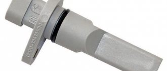
The factory speed sensor of VAZ cars is manufactured with some differences in connections to the block connector. The square-shaped connector is used in Bosh electronics systems. The circle-shaped connector is used in electronic systems such as January 4 and GM.
When connecting a sensor, you should choose devices with contact group digitization such as “-”, “A”, “+” (internal designation on the block contacts) instead of digital designations such as “1”, “2”, “3”. In addition, preference should be given to devices with a metal-type rod, since plastic rods are very short-lived.
Speed identifier in vehicle design
Repairing any kind or replacing a speed sensor is a simple procedure, but it requires a clear understanding of its structure in the car’s design. Without knowing such information, answer questions like:
- How to check the speed sensor for proper operation?
- Where is the speed sensor located?
- How to remove the speed sensor?
- What is the connection diagram for the speed sensor?
- How to replace the speed sensor?
and many others will be impossible.
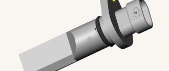
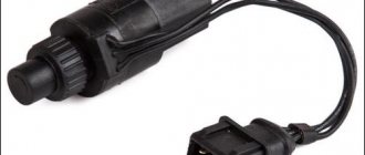
To begin with, let us repeat that the location of the speed sensor on almost all cars involves its installation in the speedometer drive (often called the sensor drive). Often, to find the speed ID, it is enough to find the wire coming from one of the front wheels and follow it to the place where it is next connected. The device he approached is a speed sensor, which is often located at the gearbox. The part almost always looks similar to the images below:
Having answered the question about where the identifier is located, you can already think about what the pinout of the speed sensor is. The typical option involves the use of wires going to:
- the sensor itself is from the speedometer drive;
- directly to the speedometer;
- main relay;
- "ground";
- controller;
- in some cases - other machine components.
Often the contact diagram of the speed sensor corresponds to the following picture:
As you can see, there are no particular difficulties in terms of location and connection of the device. Read more about how to check and remove the speed sensor below.
How to check the VAZ speed sensor
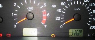
A failed speedometer sensor in a VAZ car is easily determined - in this case, the speedometer stops working, and it may also show some signs of life, but display incorrect information.
Using a tube, pliers or other available tools, rotate the sensor axis. In this case, you should see the voltmeter readings changing: the higher the speed, the higher the voltage (from 0.5 to 10 V). If this does not happen, the sensor requires replacement.
Replacing a car speed sensor
As for its location, look for the DS in the engine compartment in close proximity to the exhaust manifold. To be honest, the place where it is installed cannot be called ideal. While the car is running, the manifold heats up. The sensor wires rub against it, which over time leads to malfunctions and short circuits. Therefore, experts recommend that the first step is to properly insulate the wiring, and also use some kind of clamps so that the wires do not come into contact with the collector. This significantly extends its service life.
If the check shows that the DS is faulty, it needs to be replaced. Repairing sensors and similar small electronic devices is a thankless task. In a garage environment, this is unlikely to be possible, and the only thing that can be done is to clean the contacts from oxidation (this can be a problem).
It doesn’t matter whether you have an injection car or a carburetor with a Europanel - the connection of the speed sensor to the instrument cluster is identical.
Replacing the VAZ speed sensor: step-by-step instructions:
- Drive into the pit - it will be more convenient to work from below - and wait until the engine cools down.
- Turn off the vehicle's power by removing the cable from the negative terminal of the battery. Do not close the hood after this, this will provide you with lighting.
- Locate the speed sensor on the transmission. Clean it and everything near it with a rag to remove any dirt.
- By pressing the spring clip, disconnect the wire block from the sensor.
- Dismantle the sensor itself by unscrewing it counterclockwise - with your fingers or an open-end wrench to “22”.
- Carefully, so as not to break anything, install a new part in place of the removed part. Connect the wire block to it and the procedure for replacing the speed sensor can be considered complete.
How to properly connect a new DS? It is important here that the device rod fits correctly into the fixing sleeve, otherwise rotation will not be transmitted to the sensor. If the sensor fits into the socket the first time, then everything is in its place, and if something prevents it from moving, then the rod did not fit into the bushing.
CLICK HERE AND OPEN COMMENTS
Sorry, I didn’t understand the location of the sensor? Either write about the exhaust manifold or write about the box. These are completely different places! But my flexible shaft goes to the speedometer, which means I don’t have a sensor!
Source
Functionality check
There are several options for diagnosing DS.
The first way to check is with a multimeter:
- First you need to dismantle the DS.
- Then, using a tester, you should determine what each contact on the connector is responsible for; you need to find exactly the pulse one.
- After this, the positive probe of the tester must be connected to this contact, and the negative probe to the power unit or car body.
- Next, you should install a piece of tube on the controller axis and start rotating it at low speed. At the same time, monitor the controller readings - the higher the rotation speed of the DS tube, the higher the values on the tester display and the voltage parameter will be (the author of the video is the REMONTYCA channel).
Second method, without removing the controller:
- Using a jack, you will need to lift the front wheel of the car. Which one - right or left - does not matter.
- Then the tester should be connected to the DC wiring.
- After this, you begin to rotate the car wheel with your hands and monitor the readings on the tester display. If there are impulses, then this indicates that the DS is operating in normal mode.
If you don’t have a multimeter, you can diagnose the DC using a test light or any other 12-volt lamp.
The verification procedure is similar to the method described above:
- First, you need to disconnect the pulse cable from the DC.
- With the ignition on, using a tester, you need to find the positive and negative contacts.
- Then the front wheel of the car is raised on a jack.
- Next, the control must be connected to the signal wire. The wheel must be rotated - if at this moment the minus light on the control panel lights up, this indicates that the DS is working (the author of the video is the PivovarovNikolay channel).
As for a 12-volt light bulb, it must be connected to a battery, as well as a signal contact. If a working DS is used, the light source will blink. If the diagnostics showed that the DS is working, then it is necessary to check the functionality of its drive. To do this, jack up the front wheel, feel for the DS drive, then rotate the suspended wheel with your foot and control with your hand whether the device rotates or not.
How to check the speed/speedometer sensor on a VAZ 2110 and where it is located
The speed sensor is an element of the vehicle's electronic control system. It depends on its readings how much fuel will be supplied, how much air will bypass the throttle valve when idling, and what the speedometer readings will be. The speed sensor of a VAZ car is based on the use of the Hall effect, that is, a stream of pulses is transmitted from the device to the car's ECU, the frequency of which is proportional to the speed of the car. Auto electronics, analyzing incoming data, selects the required idle speed and sends a signal to a device that regulates the engine idle speed, which optimizes the composition of the air-droplet mixture entering the combustion chamber, bypassing the throttle valve.
What is it for?
The speed sensor has a lot of work to do. It informs the electronic control unit about the correct fuel supply, determines and sets the ignition timing, and is responsible for the quality of the air-fuel mixture.
Scheme
The sensor collects all kinds of data and transmits them in the form of signals to the electronic control unit. There, the information is checked and appropriate adjustments are made to the operation of the injection engine.
VAZ 2110 speed sensor wire pinout
Straight to the point, a break began to appear on one of the wires at a break. The difficulty was that it was not possible to remove the contacts from the chip right away (I couldn’t find any information on such a petty procedure on the Internet, there was one post where a man couldn’t remove it and sawed it off! The connector) he tore off one wire and, without torturing the remaining ones, cut off the entire connector. In general, the essence of the message, the internal appearance of the connector is misleading and at first glance it seems that the antenna that holds the contact alone is a lie! there are two of them!
To remove the contacts you will need an awl, in my case half a honey. tweezers, another difficulty is that the mustache is springy, that is, we pull the wire and press the mustache, but pull it moderately so as not to press the mustache into the plastic of the connector. Regarding the silicone inserts, they create resistance, but the moment when the contact is released is basically noticeable. If you are reading this article after you have already torn off the wire)), then it will be easier to remove it by pressing with a small flat screwdriver across the contact plates, in this case there will be room for the awl to press the mustache, but you will have to suffer.
Now recovery. The contact for restoration is very inconvenient; in the place where the wire is crimped, it has greater strength, so I don’t recommend trying to open it and insert a new wire. The maximum that I could do, without causing much damage, to remove the remnants of the wire, was to open the crimping area with a small clock screwdriver, hitting it with a hammer, but the contact must be placed on a convex surface.
Connected by soldering. If you follow my path, then get ready for inconvenience; soldering contacts to wires will be inconvenient. We put silicone plugs on the wires, strip the wires to a length of 3-4 mm, tin (I use Zil-2 flux, a 100 W soldering iron) and move the plug to the edge of the wire so that about 1 mm of its insulation is visible. We insert the wire into the contact using rotational movements. Having aligned it at the junction, apply acid. We solder carefully so that the tin does not flow into the contact and solder its insides; it will be almost impossible to remove the tin and the functionality of the contact will be lost. In the photo: the top contact is soldered, the middle contact is prepared for soldering, the bottom wire is tinned.
That's it, after soldering we go through with a dry brush to remove any remaining acid (not necessary, since during soldering it all basically boils away), spread the mustache a little, remove dirt from the connector and insert the contacts into place, pushing the contacts from the side of the silicone plug, resting against it with a screwdriver until you hear a characteristic click.
Schematic electrical diagrams, connecting devices and pinouts of connectors
The speed sensor is an element of the vehicle's electronic control system. It depends on its readings how much fuel will be supplied, how much air will bypass the throttle valve when idling, and what the speedometer readings will be.
The speed sensor of a VAZ car is based on the use of the Hall effect, that is, a stream of pulses is transmitted from the device to the car's ECU, the frequency of which is proportional to the speed of the car. Auto electronics, analyzing incoming data, selects the required idle speed and sends a signal to a device that regulates the engine idle speed, which optimizes the composition of the air-droplet mixture entering the combustion chamber, bypassing the throttle valve.
During a distance of one kilometer, the speed sensor transmits over 6000 pulses to the ECU. Based on the parameters of the time analysis of inter-pulse signals, the on-board computer transmits data to the dashboard, thereby determining the speedometer readings.
As in many other cars, the VAZ speed sensor is located in the upper part of the gearbox housing, not far from the engine oil level dipstick. You can get to it from two sides: from above, by opening the hood and disconnecting the adsorber, and from below, using the inspection hole for convenience.
Principle of operation.
The principle of operation of the VAZ 2110 speed sensor is based on the Hall effect: by transmitting electrical impulses (in VAZ cars, by the way, only 6 such impulses are used) to the ECU, the sensor informs it about the rotation speed of the driving rollers of the machine, on the basis of which the control unit not only acts to the speedometer needle/mileage display, but also monitors engine operation by sending the necessary signals to the idle speed controller and throttle position sensor.
Purpose and location
As we noted above, the sensor determines the speed of the vehicle and transmits the received data to the speedometer, where they are reflected. Speedometers are either pointer or liquid crystal.
The shaft is the main element of the product. It rotates and passes near a special mark once per circle. At this moment, a pulse is sent to determine the number of revolutions per minute.
The number of signals depends on the rotation speed of the shaft, the value of which is coordinated with the transmission shafts and wheel diameter. Thanks to this, information from the speed sensor is converted and sent to the speedometer.
The DS consists of three elements - the speedometer drive, the casing and the controller, through which the product is connected to the vehicle's electrical network. Depending on the make and model of the car, the appearance and design may vary.
The location of the speed sensor is also different. Before checking it, you need to find the device.
Common mounting locations are the transmission output shaft or transfer case (for all-wheel drive vehicles).
Older models used a cable that was screwed onto the speedometer drive. Today its place is taken by a speed sensor, connected using ordinary wires.
How to check the VAZ speed sensor
A failed speedometer sensor in a VAZ car is easily determined - in this case, the speedometer stops working, and it may also show some signs of life, but display incorrect information.
Using a tube, pliers or other available tools, rotate the sensor axis. In this case, you should see the voltmeter readings changing: the higher the speed, the higher the voltage (from 0.5 to 10 V). If this does not happen, the sensor requires replacement.
Checking induction DC and with reed switch
Note that speed controllers differ in the signal coming from the wheels. Taking this fact into account, the DS check is also built:
- WITH REED SWITCH. The signals are rectangular in shape. The cycle is from 40 to 60 percent. Switching occurs at a voltage from 0 to 5 Volts or when the battery voltage is reached.
- INDUCTION. With these speed sensors, the signal is in the form of waves, so the voltage changes based on the speed at which the wheel spins. This can be seen on the oscilloscope. Otherwise the principle is identical to what happens on the crankshaft angle controller.
Replacing a car speed sensor
As for its location, look for the DS in the engine compartment in close proximity to the exhaust manifold. To be honest, the place where it is installed cannot be called ideal. While the car is running, the manifold heats up. The sensor wires rub against it, which over time leads to malfunctions and short circuits. Therefore, experts recommend that the first step is to properly insulate the wiring, and also use some kind of clamps so that the wires do not come into contact with the collector. This significantly extends its service life.
If the check shows that the DS is faulty, it needs to be replaced. Repairing sensors and similar small electronic devices is a thankless task. In a garage environment, this is unlikely to be possible, and the only thing that can be done is to clean the contacts from oxidation (this can be a problem).
It doesn’t matter whether you have an injection car or a carburetor with a Europanel - the connection of the speed sensor to the instrument cluster is identical.
Replacing the VAZ speed sensor: step-by-step instructions:
- Drive into the pit - it will be more convenient to work from below - and wait until the engine cools down.
- Turn off the vehicle's power by removing the cable from the negative terminal of the battery. Do not close the hood after this, this will provide you with lighting.
- Locate the speed sensor on the transmission. Clean it and everything near it with a rag to remove any dirt.
- By pressing the spring clip, disconnect the wire block from the sensor.
- Dismantle the sensor itself by unscrewing it counterclockwise - with your fingers or an open-end wrench to “22”.
- Carefully, so as not to break anything, install a new part in place of the removed part. Connect the wire block to it and the procedure for replacing the speed sensor can be considered complete.
How to properly connect a new DS? It is important here that the device rod fits correctly into the fixing sleeve, otherwise rotation will not be transmitted to the sensor. If the sensor fits into the socket the first time, then everything is in its place, and if something prevents it from moving, then the rod did not fit into the bushing.
How to check the speed sensor, what types they are and where they are located on VAZ 2110 (2111, 2112 or 2115) cars.
What should be done in such cases
In the first case, we do not necessarily need to change the speed sensor itself. First, we have to familiarize ourselves with the connection diagram of the device and all the electrical wiring. First, let's check the contacts. They need to be cleaned and it is advisable to insulate them somehow - liquid rubber or oil-water-resistant electrical tape are quite suitable. If you don’t have this on hand, you need to at least lubricate them with Litol or some other product that you have in your garage.
Secondly, if the cause has not yet been eliminated after cleaning and sealing the contacts, we carefully review all the wiring, since even minor damage to them will lead to this type of malfunction. Most often, the rupture occurs near the contacts or near the exhaust manifold.
When is diagnostics needed?
Due to the limited number of pulses and for many other reasons (motor oil, dirt has gotten on the sensor, contacts or wires located near the speed sensor have oxidized, there is mechanical damage to the part, etc.) in the “tens” it is often possible to observe flaws in the operation speedometer or its complete inoperability. At the same time, most often, problems arise when coasting at idle and the “CHECK” system lamp turns on (error code “24”). Be that as it may, any of the mentioned signs requires the car owner to mandatory diagnose the speed sensor, because the causes of malfunctions may lie in it, or they may lie in a completely different place.
Some recommendations
- The search for the cause of the speedometer's inoperability should begin with an external inspection of the DS and the wires going to it. Wires often break in close proximity to the plug.
- If the speed sensor is covered with a layer of dirt or oily, you need to remove it, wipe it, reinstall it and check the speedometer readings again. Perhaps after this the instrument needle will again begin to show speed normally.
- If you cannot figure out the problem yourself, you should contact an electrician at a car service center.
Speed sensor
Carburetor models use a cable mechanical speedometer system, so there is no speed sensor. It's simply not needed.
Speed sensor malfunctions
Typical symptoms of failure of the electronic speed sensor may be:
- lack of electrical signals - error code P0500;
- intermittent electrical signals with EMF - error code P0503;
- the arrow moves chaotically in different directions, incorrect readings or other types of incorrect operation of the speed indicator;
- unstable operation of the engine at idle: interruptions, floating speed, etc.;
- increased consumption;
- power failures, when you press the pedal the engine does not “pick up” speed, etc.
There can also be several reasons for problems with the Electronic Speed Sensor, for example:
- power supply circuit break,
- oxidation of contacts,
- breakage of connecting wires or wear of the mechanical drive of the sensor.
Signs and causes of malfunction
Symptoms indicating the need to check the speed sensor have already been indicated above. The main signs of a malfunction are the absence of readings on the speedometer, increased “gluttony” of the engine, malfunction of the engine at idle, deterioration in dynamics, etc.
A breakdown of the sensor may be indicated by engine stopping while driving, failure of the electric power steering wheel, or increased sensitivity of the FLS (for example, for Lada Kalina).
Common causes of sensor failure:
- violation of the integrity of contacts;
- oxidation at joints;
- open circuit;
- insulation melting;
- wear of the speedometer cable, etc.;
- strong vibration of the device;
- dirt ingress;
- temperature changes;
- Other reasons.
If you ignore problems, engine malfunctions occur and wear on its elements increases.
As a rule, the cause of problems is dirty contacts, which should be cleaned and treated with Lithol.
If there is a break in the electrical circuit, the damage should be looked for near the connection connector. This is where the wires are most susceptible to bending and breaking. Sometimes the insulation becomes damaged where the exhaust manifold is mounted.
When exposed to high temperatures, the insulation can be damaged, which leads to short-circuiting of the wires.
With prolonged use, the speedometer cable wears out, which eventually develops cracks and breaks, which leads to failure of the controller.
An equally common cause of speed sensor failure is a broken circuit, so before replacing the device you need to make sure it is working properly.
To begin with, you should discard the power supply and examine the contacts from the point of view of contamination. After cleaning, the surface is treated with Litol lubricant.
During the test, measure the resistance in the grounding circuit; it should be equal to one Ohm.
When analyzing a fault, consider the following:
- If the controller is working properly and the gear is intact, it is possible that the device is not receiving power or there is a short circuit in the network.
- The readings on the dashboard involve the ECU and ABS, so you need to check the integrity of the wire running from the speedometer to the unit. It happens that the dashboard itself fails.
- On cable-driven machines, the cause of the malfunction is often hidden in old oil on the gear or a worn square at the end of the cable.
Before replacing the sensor, make sure what is causing the problem. The algorithm of actions is as follows:
- take the cable out of the box, twist it and look at the speedometer’s reaction;
- check the electrical part of the speed indicator;
- if there is no voltage, you need to make sure the fuses are intact;
- remove the speed sensor, install the cable in the KPI and drive a short distance (if there is no data on the speedometer, we can talk about a breakdown of the DS).
Finding out the cause of the malfunction requires an integrated approach, as does checking the sensor (discussed below).
Also read about signs of a malfunctioning mass air flow sensor.
Vehicle traffic control
This function is performed by the speed sensor, which takes part in the formation of the fuel mixture by the controller. It replaced the mechanical cable drive previously installed on carburetor VAZ 2112 models. The operating diagram of the element is as follows:
A malfunction of the speed meter is indicated by such signs as failure of the speedometer, unstable operation of the power unit and loss of idle speed when coasting. An indirect sign can also be the short-term display of the “Check Engine” sign on the instrument panel. If you pay closer attention, increased gasoline consumption will become noticeable. If the sensor fails, you can continue driving, but you should replace it as soon as possible. The product cannot be repaired.
How to find out if our device is faulty
We may not always notice problems right away. This can turn into a huge problem - from a fine for speeding to road accidents and accidents.
Let's look at the main symptoms of a malfunction:
- It seems to you that the speedometer does not display the speed of your car correctly.
- Faulty idle.
- Lately you have been experiencing increased gas mileage.
- You can hear from the sound of the engine that it is not working at full power.
If we consider the complaints of car owners, then most often problems arise precisely with stopping the engine when the car is coasting, or during gear changes when the clutch is depressed.
How to check the speed sensor
Most often, the failure of the EMF is a consequence of a break in the electrical circuit. Therefore, it is first advisable to check the integrity of the wiring and the condition of the connectors (contacts).
It is easy to check the functionality of the electronic sensor with your own hands if you have a multimeter. To do this, you must first dismantle the product. Then determine the contact through which electrical impulses are transmitted.
It is usually located in the middle of the block.
- Connect it to the positive lead of the measuring instrument.
- Having closed the negative cable to the machine body, rotate the EMF rod within a speed of 5 mph.
- Check the multimeter readings.
- As the rotation intensity increases, the device readings (frequency and voltage) should increase proportionally.
Instrument panel test on video (speedometer self-diagnosis)
There are some things we don't specifically consider.
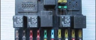
Power to the circuit shown in the previous chapter comes from main relay 6. It is also called the “ignition relay”. There is also fuse 1 in the circuit.
Additional relay and fuse box
When the ignition circuit is broken, both the speedometer and the ECU module do not work on the VAZ-2112, and the engine does not start at all. So advice about checking the relay would seem stupid.
Advice for those who have an oscilloscope
If you still decide to dismantle the sensor, connect a 1 kOhm resistor to its output (to the middle terminal). The resistor tap is connected to the “plus” of the power supply. By turning the shaft by hand, pulses can be observed at terminal 2. There are six pulses per revolution.
VAZ speed sensor pinout and DS connection diagram
The speed sensor is an element of the vehicle's electronic control system. It depends on its readings how much fuel will be supplied, how much air will bypass the throttle valve when idling, and what the speedometer readings will be.
The speed sensor of a VAZ car is based on the use of the Hall effect, that is, a stream of pulses is transmitted from the device to the car's ECU, the frequency of which is proportional to the speed of the car. Auto electronics, analyzing incoming data, selects the required idle speed and sends a signal to a device that regulates the engine idle speed, which optimizes the composition of the air-droplet mixture entering the combustion chamber, bypassing the throttle valve.
Description
The speed sensor harness (cable) installation kit is designed for DIY workshop assembly of the speed sensor harness.
This kit allows you to reduce the costs of the workshop and, what is also important, it allows you to speed up the process of installing the tachograph by selecting the most convenient wire length.
Pinout of standard speed sensor harness:
There is also a pseudo-standard for harnesses that you may encounter, meaning the color scheme of the wires. As a rule, harness manufacturers arrange pinouts according to the following rule:
When assembling, you need to pay attention to the quality of the wire used. Pay attention to the technical characteristics of the wire when purchasing; the prerequisites are:
- Section 4x0.75
- twisted pair
- Benzo-Oil resistance
After the final assembly of all connectors, the cable (wire) must be laid in a non-flammable corrugated pipe, we also draw your attention to the fact that at the moment it is difficult to find a non-flammable corrugated pipe, this is due to the large predominance of Chinese suppliers in the Russian market. The corrugation is checked very simply, set it on fire and see if the non-flammable one goes out on its own, the Chinese one burns a little quieter than gunpowder. I think it’s unnecessary to explain why it is recommended to use non-flammable.
When installing the finished speed sensor harness on a car, pay attention that it is laid away from all heating elements (manifold, muffler, radiators, auxiliary heater, flame extinguisher)
The speed sensor harness is laid next to the main wiring harness of the vehicle, fastening is done using thermally protected ties (for outdoor street installation).
All connections are sealed.
Location of all elements
On VAZ 2110-2112 cars, electronic sensors are located as follows:
- Coolant temperature control. Installed in a large pipe coming out of the engine on the right side (in the direction of travel).
Wires go from all electronic monitoring devices to the processor, which must be checked periodically, since insulation failure often causes replacement of the measuring elements themselves. Naturally, such a replacement of a VAZ 2110 speed sensor or other device will not produce results without installing new wiring.
Replacement instructions
If the malfunction is confirmed and the sensor needs to be replaced, the work is done according to the following algorithm:
- Turn off the ignition, open the hood and remove the terminal from the battery.
- Search for speed sensor. It can be located in different places, it all depends on the car model. This information can be found in the service book.
- Cleaning from contaminants. This is necessary to avoid foreign elements getting into the transmission.
- Removing the power connector and unscrewing the device. If you cannot disconnect the controller, you should treat the connection location with WD-40. It is not recommended to apply excessive force, as this may lead to damage to the integrity of the case. After applying the specified liquid, you need to wait some time.
- Removing the old and installing a new sensor, connecting wires.
- Resetting errors on the ECU (for models that have an electronic unit). If this work is not done, the light on the dashboard will light up, and the ECU will send signals about a breakdown.
Pinout DS 2109, 2110, 2112, 2114, 2115
If you understand how to connect the speed sensor, then there is the following pinout that you should follow. At the same time, it is important to understand the essence of the operation of the DS to study the circuit diagram of the sensor, which is attached to this article.
The factory speed sensor of VAZ cars is manufactured with some differences in connections to the block connector. The square-shaped connector is used in Bosh electronics systems. The circle-shaped connector is used in electronic systems such as January 4 and GM.
When connecting a sensor, you should choose devices with contact group digitization such as “-”, “A”, “+” (internal designation on the block contacts) instead of digital designations such as “1”, “2”, “3”. In addition, preference should be given to devices with a metal-type rod, since plastic rods are very short-lived.
. 2705, 33021 “”
. 9.51. : 1 , 2 5-54, 3
, p. 9.51. 5-54 10 3, 6+1 200250. :
. 9.52. : 1, 2, 3, R1 -0.25-10, V1 102
. 9.53. : 1 ; 2 ; 3 5-54
, . 9.53. 5-54 1 6 , 122 200250 . 240 1000+100 -1, 960 4000 -1.
P. 9.54. : 1 ; 2 ; 3 1, 4, R1 -2-330, R2 -2-120, R -2-15
, . 9.54. RI, 0, R2 1/2, R3. . : 330+15, 11+5. 70 ( ) 118+10 .
25 14001900 , 80 200270 .
. 9.55. : 1 ; 2 ; 3 1 ; R1 -2-250
. 9.56. : 1 ; 2 ; 3 1 ; 4 ; R1 -2-180 ; R2 -2-60
, . 9.56. R1 1.5 /2, R2 4.5 /2. .
290330 , 1,5 /2 170200 , 4,5 /2 5080 .
30 I (5-48). , . 12 14 +0.4 .
Preparatory activities
Proper replacement of the speed sensor on a VAZ 2110 implies the mandatory purchase of a new device that meets all the requirements of your car.
Connector
Basically, when purchasing a device, follow two basic rules.
- Choose a sensor whose connectors inside the block are marked -, A and +. Usually the designations 1, 2 and 3 are used there. There is no fundamental difference between them, it will simply be much easier to carry out the pinout with such markings. It is the incorrect connection that often becomes the reason that you have to seek help from a service station. And these are completely different financial costs.
- The rod on the element must be made of metal. If the stem is plastic, it will last you about 6 months. It is not in your best interest to replace regularly. But don’t forget to check the metal rod for play, correct rotation, and the presence of a washer in the package.
Installation process
The whole process can be divided into several stages:
- inspecting the car to determine whether it is necessary to replace the speed sensor and speedometer;
- selection and replacement (if necessary) of the speed sensor and speedometer;
- connecting the tachograph wires to the speed sensor and speedometer;
- examination;
- calibration and activation of the CIPF unit (performed in a specialized center).
Now about each point in more detail.
Speed sensor and speedometer
When inspecting the vehicle, you need to pay attention to the speed sensor and speedometer. If the speedometer is mechanical with a cable, then it definitely needs to be replaced, and you will also need to install a speed sensor. It is possible to use a pass-through sensor to keep the old speedometer, but this option is only a last resort. When installing a tachograph on a Kamaz , you may encounter speed sensors in the form of a small generator, which, depending on the speed, changes the voltage that is supplied to the speedometer, in which a motor is installed, the rotation speed of which directly depends on the voltage. When installing a MAZ tachograph, we may need an adapter for installing a new speed sensor; it can be picked up in a store or machined (for special extreme sports enthusiasts).
Now we connect the device to the on-board network
The tachograph connection diagram is usually different, this is caused by the huge number of not only car brands, but also their modifications. As a rule, the main wires to be connected during installation are: - power supply +12\24 Volts. It is taken from 1 power circuit or pulled from the battery; - weight. It is connected to the housing or pulled from the terminal block with ground. if there is no mass on the body/body of the vehicle (for example, MAN cars); — ignition. As a rule, it is located on the ignition switch (toggle switch) or under the dashboard, designated as ACC; — turning on the headlights/low beam. Designed to automatically adjust the brightness of the tachograph display, taken from the fuse box in which the fuse is from the light or from the wire to the headlights under the dashboard; — power supply for the speed sensor. Power goes from the tachograph to the sensor. Everything is simple here, according to the diagram on the sensor we apply a plus; — weight of the speed sensor is the same; — signal from the speed sensor. We simply connect from the sensor directly to the connector; — output to the speedometer. Connected for the speedometer to work. The connection is made from the tachograph, and not from the speed sensor. Twists “all in a bunch” are not allowed! — additional equipment as necessary (fuel level sensors, temperature sensors and additional equipment).
How to check the VAZ speed sensor
A failed speedometer sensor in a VAZ car is easily determined - in this case, the speedometer stops working, and it may also show some signs of life, but display incorrect information.
Using a tube, pliers or other available tools, rotate the sensor axis. In this case, you should see the voltmeter readings changing: the higher the speed, the higher the voltage (from 0.5 to 10 V). If this does not happen, the sensor requires replacement.
Source
Subtleties of checking for different car models
Depending on the vehicle, the location, malfunctions and details of the check may vary.
VAZ-2110
A common malfunction on the “ten” is incorrect operation of the odometer, expressed in incorrect speed data. The cause may be a broken speed sensor or drive.
Sometimes the malfunction is due to oxidation of the connectors or damage to the wiring.
The sensor is located near the collector, so the cause of the breakdown may be damage to the wiring due to high temperature.
To check the performance of the product, you can use one of the three methods discussed above.
If the device is faulty, replacement will require a 21 or 22 key. When purchasing a new speed sensor, it is recommended to choose a product with a metal rod. It lasts longer and is more reliable.
Kalina
As with other models, a popular reason for DC failure is damage to the wiring (oxidation, rust, poor contact, melting wires, etc.). A multimeter is used for control.
The probes are connected to the central contact (“plus”) and to the body (“minus”). When vibrations occur, the voltage should vary from 0.5 to 10 V.
You can check the operation in other ways - by hanging the wheel or using a test lamp.
The location of the Lada Kalina DS is shown below.
Priora
There are a number of features in checking the Lada Priora speed sensor. Often a problem with it is indicated by error P0501.
Algorithm of actions:
- Inspection of the controller.
- Checking the quality of grounding at the contact connection.
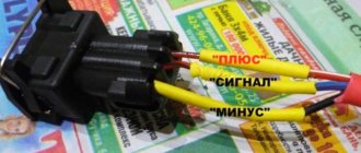
- Reference voltage measurement. The Priora speed sensor has wires of different colors. It is located behind the collector.
Brown has a minus sign and pink has a plus sign. The signal wire is made in gray color. Using a multimeter set to voltage measurement mode, you need to check the reference U. The optimal value is from 12 V. If there is no voltage or it is less than the set parameter, you need to charge the battery and look for a breakdown elsewhere (ECU or power supply circuit). - Checking the quality of connector connections using a thin needle or plate. It is important that the contact groups do not fall out of the connector.
- Checking the speed sensor using an oscilloscope (the wheel must rotate at a speed of more than 5 km/h).
Before checking the DC, it must be removed from the vehicle, but the wires must not be disconnected.
Next, turn on the ignition and check the output voltage. To do this, you need to slowly change the rotation speed of the axis. The curve should have a voltage of five to one volt in the reverse direction.
If the voltage remains unchanged, this indicates a breakdown. An additional sign of failure is the engine stopping when changing gears, failure of the electric power steering.
To check the speed sensor, you can use a simulator - a device that changes the pulse frequency by pressing plus or minus. Using the product you can also check the machine's ECU.
Gazelle
To check the Gazelle speed sensor, you need to take the following steps:
- Unscrew the screws that secure the hatch near the gearshift knob.
- Remove and unscrew the DS chip.
- Check the operation of the device, starting with checking the grounding on the third contact. The first contact should have a voltage of +12 V. The black wire is “negative”, the yellow wire is “positive”. Green goes to the DS and instrument panel.
It is worth considering that the “positive” signal is sent to the DS and the reverse signal. If the reversing lights turn on after moving the gearshift knob to the appropriate position, there is no need to check the fuses.
Nissan
Nissan uses two input signals from the automatic transmission control unit - from the speed sensor and the vehicle speed sensor.
The first determines the rotation speed of the secondary shaft and sends information to the unit, and the second is used as an additional controller. It sends data when the master node is faulty.
The Nissan speed sensor is built into the speedometer assembly and plays the role of an additional device. Symptoms of a malfunction are dropping into neutral or illogical gear shifting.
The sensor itself is located behind the left fender liner, and to replace it you need to remove the left plastic protection (using the example of a Nissan Liberty).
If error “2” appears, you need to check the DC chain, the integrity of the wires and connectors. Studying the operation of the controller itself is carried out according to the standard scheme:
- removing the speed sensor (VSS) from the transmission housing;
- connecting a voltmeter to the terminals and switching the multimeter to AC mode;
- rotation of the drive gear (there should be a voltage with an amplitude of about 0.5 V);
- If there is no U, the sensor needs to be changed.
If tension is present, you need to look for another reason.
To replace the DS you need:
- put the car on a jack;
- discard the wiring from the sensor;
- unscrew the coupling bolt, loosen the clamp and remove the device from the transmission;
- check the condition of the o-ring (if necessary, replace it);
- Put the product in the reverse order.
Niva
The Niva's speed sensor is located on the transfer case. It is made in a plastic case, and inside there is an electronic part.
The device is highly fragile, so you need to be careful.
Check procedure:
- disconnecting the sensor;
- connecting the red (“positive”) probe to the product contact;
- connecting the minus to ground;
- fixing the tube on the shaft for rotation;
- switching the device to voltage measurement mode;
- shaft rotation and U control (this parameter must be changed).
To replace, you need to disconnect the terminals from the battery, press the plastic lock and use a wrench to unscrew the sensor (to simplify the work, you can use WD-40.
VAZ 21093 injector
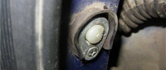
The VAZ 21093 injector speed sensor is located on the speedometer drive mechanism (at the gearbox). To find it, just open the hood and remove the adsorber.
Performing the last step is not necessary, but it is easier to get to the desired point in another way. On the right CV joint side there is a wire that goes to the gearbox. It connects to the connector of the desired sensor.
In the case of injection VAZ-2109, the main sign of a speed sensor failure is the engine stopping at idle or when the clutch is pressed.
Also, a light on the dashboard lights up asking you to check the engine (code 24). For control, one of the three methods discussed earlier is used.