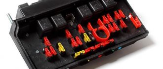
Oka brand cars are equipped with cylindrical type fuses. Total number of modules: 10 pieces, relays - switches 5 pieces.
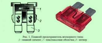
Due to ineffective design and outdated technology, fuses often fail and melting elements burn out. The process of replacing with new ones is not at all complicated, but it is not always rational. Many car enthusiasts practice installing knife-type modules. This is a modern design with a melting element in the center.
Installation of blocks is no more difficult than cylindrical ones; every car enthusiast can cope with the task.
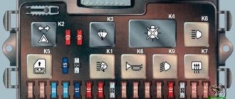
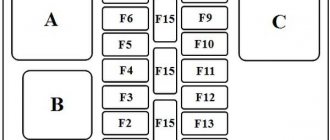
Fuse installation diagram
| Marking | Scheme |
| Fuse (1) / 15 | Stove heater |
| Fuse (2) / 10 | Fan activation sensor |
| Fuse (3) / 5 | Windscreen wipers |
| Fuse (4) / 5 | Carburetor solenoid valve |
| Fuse (5) / 15 | Turn signals. Alarm |
| Fuse (6) / 20 | Tail lights, oil pressure, battery |
| Fuse (7) / 20 | High beam, low beam, dimensions |
| Fuse (8) / 15 | License plate light |
| Fuse (9) / 5 | Power socket, interior lighting |
| Fuse (10) / 5 | Cigarette lighter |
The cost of the original fuse block assembly (hereinafter referred to as the BP) starts from 1,200 rubles. high-quality analogues from 800 rubles.
Symptoms of failure
To check the functionality of the generator, a test lamp is included in its connection diagram. If the device is working properly, the control lights up before the engine starts, indicating that the circuit is in working condition, and after the power unit starts, the light should go out.
It is by the indicator lamp, as well as a number of indirect signs, that a generator malfunction can be identified:
- The signal does not light up when the ignition is turned on, while the other measuring instruments are working. Such a problem may indicate a malfunction of the light bulb itself or an open circuit in its power supply;
- It does not light up and other devices do not work. This may indicate a blown fuse, an open circuit in the instrument panel, or a faulty lock or ignition relay;
- The light glows when the engine is running. This may occur due to breakdown of rectifier diodes, regulator malfunction, short circuit or breakage of stator windings, weak drive tension;
- The lamp works normally, but the Oka generator does not charge (the battery is often discharged). This problem can arise as a result of broken contacts in the wiring suitable for the device, a malfunction of the regulator, a malfunction of the rectifier, broken commutator wires, wear of brushes or slip rings;
- The lamp works fine, but the battery is being recharged (it often boils). Here the reason should be sought in the voltage regulator.
The control lamp allows you to identify mainly electrical faults. As for mechanical breakdowns, they manifest themselves in the form of extraneous noise when the engine is running - hum, squealing, whistling. Often such symptoms are caused by loosening the drive tension. But if adjusting the belt does not eliminate the noise, then you should check the condition of the bearings.
Replacing fuses on Oka
The PSU installation process is quite simple and intuitive. At the preparation stage, we check the availability of:
- Collar;
- Heads on "10";
- A new old-style power supply unit (cylindrical type) or a knife type, if the owner decided to upgrade;
- Additional lighting as needed if work is carried out in conditions of limited visibility.
Replacement steps:
- Place the car on a flat surface, open the driver's door wide;
- We wedge the rear row of wheels with wheel chocks and squeeze the parking brake lever. This is necessary for personal safety during work;
- Open the hood, unscrew the power terminals from the battery to prevent a short circuit in the on-board circuit;
- We snap off the cover from the power supply unit and squeeze the plastic clips on the sides;
- Using a 10mm socket, unscrew the mounting bolts on the sides. We remove the power supply from the seat.
Next, we insert a power supply with knife-type fuses; if we are upgrading the equipment or identifying a faulty module, we replace it with a new one.
- Screw the bolts and put on the protective cover.
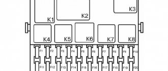
Replacing the turn signal and hazard warning relay
You will need a “10” key
. The turn signal and hazard warning light relay, type 494.3747, is located behind the instrument cluster and is secured with a nut to the front panel stud.
The relay is marked on the cover of its housing.
14. Press out the two spring latches located on the sides of the instrument cluster from the inside of the instrument panel and.
15. . remove the combination from the instrument panel.
16. Unscrew the nut securing the speedometer cable and.
17. . Disconnect the speedometer cable from the instrument cluster.
18. Label the terminals and wire connectors.
19. Disconnect the pads from the instrument cluster and remove the combination.
20. Unscrew the relay mounting nut and remove the relay from the body front stud.
21. Disconnect the relay from the wire block (shown by the arrow). Install the relay in the reverse order of removal.
Refueling the car GENERAL INFORMATION You will need a canister of gasoline a funnel Warnings Use gasoline with an octane rating of 91–95. Using gasoline with a lower octane number may result in malfunctions.
Instrument cluster – Checking the sensor and coolant temperature indicator. Location of lamps in the instrument cluster (reverse side) 1 – fuel reserve warning lamp; 2 – instrument cluster illumination lamps; 3 – control lamp for turning on the side light; 4 - .
Headlight switching relay To switch on the headlights, relays of type 904.3747-10 are used, installed in the mounting block. The relay switching voltage at a temperature of (23±5)°C is no more than 8 V, and the winding resistance is (85±8.5).
The turn relay installed (including) on the Oka was born in agony. You can read about this in a book about the history of VAZ. I have long wondered why 4 contacts are used, but the connector is 6-pin, I found the answer in the Khodasevichs’ book. Initially, the relay was 5-pin and pin 5 served to block the subsystem for monitoring the health of the lamps. Then it was abolished, but the connector was not changed for compatibility.
And with the advent of the “tens”, they finally switched to separate indication of turns. At one time, I “wrote with boiling water” about this. Accordingly, 11116 has an old relay and the left and right turn indicators are connected by a jumper and connected to pin 3 of the relay. When lisalis-n installed such a tidy for herself, she complained that something was wrong - both turns were blinking together. So, in order to do it as it should, and not as expected, you need to change the relay and redo the tidy. It is better to change the relay first (a new relay works without an indicator at all)
Scheme 11115 of the instrument panel is identical to 2110 (2114) so we find either two contacts connected by a blue jumper or contacts 5 and 6 of the second connector. Photo of connectors here
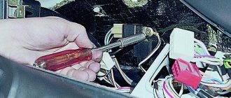
How to identify a blown fuse
It is quite simple to assess the condition of cylindrical type modules, as well as knife type ones. In both cases, a melting element is laid in the center of the fuse.
As soon as the current exceeds the permissible value, the plate instantly melts, opening the contacts. A small black spot forms, which is evidence that the part is faulty.
The module is removed from its seat using special plastic tweezers. In life, an accessory is often lost, so it is practiced with your fingers. After replacement, we put the power terminals on the battery, start the engine, and test the system.
Lamp burned out
Naturally, if any light source does not turn on, the first thing that comes to mind is that the light bulb has burned out. The design of car lamps is such that the low beam may indeed be absent, but the high beam remains available. Halogen lamps have two filaments. It is quite possible for one of them to rupture - in this case, the light for which it is responsible will be absent.
To replace the bulb, the services of an auto electrician are not required. It is enough to open the hood with the ignition off, remove the protective box on both sides of the headlight, pull out the contact group, disconnect the spring clips, remove the burnt out bulb and install a new one.
A little subtlety:
The flask should be wiped with alcohol before installation, otherwise it will burn instantly. It is also not recommended to handle the bulb with unprotected hands: there is always some greasy and damp secretions on them, which can damage the light bulb. The best way to do this (replace the lighting) is with a dry cloth or rag.
Common causes of fuse failure
- Systematic (periodic) power surges in the network;
- Oxidation of contacts on terminals, end switches;
- Damage to the insulating layer of the wiring, which leads to a “short-circuit” to ground, the car body;
- Damage to the body, impact, collision with oncoming traffic;
- Water entering the housing, condensation formation;
- Installing the module in a low current range;
- Unprofessional installation by the owner of the equipment.
Disassembly
Disassembling the generator, in general, is not difficult, with the exception of one point - removing the pulley. You can fix the rotor in order to loosen the pulley fastening nut using a special tool. device An alternative removal option is to fix the pulley itself in a vice using elastic attachments (for example, a belt can be placed between the pulley and the jaws).
The general operating technology of the generator is as follows:
- Remove the pulley (using a tool or a vice);
- Disconnect the capacitor wire and dismantle the capacitor itself;
- Unscrew the regulator mount and remove it;
- Unscrew the coupling bolts;
- Use a puller to tighten the front cover;
- Remove the rotor;
- Unscrew the fasteners of the stator leads to the rectifier;
- Remove the stator;
- Unscrew the nuts securing the rectifier to the back cover;
- Remove the rectifier;
After disassembly, all that remains is to remove the front bearing, which is installed in the front cover, for which you need to unscrew the bolts holding the fastening washers together.
Having finished disassembling, we clean all parts and troubleshoot. Some types of faults can be determined visually, but for such faults as breaks and short circuits of the windings, the Oka generator needs to be checked using measuring instruments. For example, to test the regulator, you need a charger with regulated voltage.
This component is checked like this:
- We connect a charger to the output and ground of the regulator, and a 12-volt light bulb (control) to the brushes;
- We apply a voltage of 12 volts, and the lamp should light up;
- We increase the voltage to 15 V (in a working regulator the control should go out);
If the lamp does not light up at 12 V or does not go out at 15 V, the regulator is faulty and requires replacement. As for the stator windings, it is better to entrust their inspection to an experienced auto electrician.
Assembly of the unit is carried out in reverse order
In this case, special attention should be paid to the correct connection of the generator, or rather all its terminals and wires
If an auto electrician determines that the device cannot be repaired, it will have to be replaced with a new one. And what makes the generator suitable for Oka is indicated above.
Recommendations for caring for BP
- Strictly observe the time intervals for technical inspection, even when the factory warranty has expired;
- Buy mainly original parts;
- Carefully check the catalog article numbers with the data specified in the vehicle’s operating manual;
- In the absence of experience, carry out repairs in certified workshops, where they provide a quality guarantee;
- To a lesser extent, use the services of unverified craftsmen, suppliers of parts and components.
Main malfunctions and why the starter does not turn?
Malfunctions of the Oka starter, as well as the power electric motors of cars, are divided into two categories - mechanical and electrical. The first includes:
- Wear of armature support bushings;
- Damage to gear teeth;
- Jamming of the retractor relay armature;
- Development of splines for the armature shaft;
The most common mechanical failure is wear of the support bushings, which subsequently becomes the cause of other breakdowns. Due to significant wear of the bushings, the position of the armature and, accordingly, the bendix are disrupted. As a result, it is more difficult for the gear to engage, the wear rate of the teeth increases, and they may crumble.
Electrical faults include:
- Breakage of stator windings, armature, solenoid relay;
- Heavy wear of collector plates;
- Critical wear of brushes;
- Closing the windings;
- Burning of “nickels” of power contacts;
To this category of breakdowns you can also add problems with the power circuits of the electric motor and relay.
Turn relay VAZ 2101
Malfunctions of the Oka starter manifest themselves in different ways:
- The starter does not turn on, there are no additional sounds;
- You can hear the activation of the solenoid relay, but the electric motor does not turn;
- The starter rotates, but picks up speed;
- Extraneous sounds are heard when turned on (crunching, grinding);
If such signs occur, the unit should be repaired.
Differences between old and new PSUs
- There are no significant differences in functionality. Both blocks work equally efficiently. Another thing is that the modification of cylindrical type fuses is outdated and it is becoming more and more difficult to find components every day.
- Some creative motorists practice installing a power supply on Oka from Lada 10 - 15 models. Theoretically, such an upgrade is possible, but it will just require a lot of knowledge and experience in assembling electrical circuits.
- You need to re-solder the entire power supply, five relays - switches. Loop the parts onto one board and fix it to the frame under the dashboard. To ensure safe work, use the services of certified workshops and auto electricians.
- Remember that unprofessional intervention is more likely to harm than improve the efficiency of a particular unit.
- The average service life of an old-style power supply is 60 – 65 thousand km. The service life of blade type fuses is 80 – 90 thousand km. Depending on operating conditions, quality and professionalism of assembly, the interval can be increased to 5 - 10 thousand km.
- When purchasing parts, carefully check the catalog numbers with the data in the operating instructions for the technical device.
Electrical diagram of VAZ-11113 with symbols
The electrical circuit of the VAZ-11113 does not differ significantly from the VAZ-1111. The car was equipped with a modernized version of the power unit and some components that had virtually no effect on the electrics.
Contactless ignition diagram indicating the main elements and connecting wires
Contactless ignition VAZ-11113
- 1 - control relay;
- 2 — ignition switch with contact group;
- 3 - protective fuse;
- 4 - controller;
- 5 - sensor that determines the moment of spark supply;
- 6 - common ignition coil;
- 7 - candles.
The principle of operation of turn signals
Turn signals (direction indicators) are an essential part of the lighting equipment of any vehicle. On each vehicle they must be installed on both sides, front and rear (on trailers - only the rear) and are orange lights (in some countries red is allowed). Before starting the maneuver (the exact distance or time is not regulated by traffic regulations), the driver must turn on these lights on the side in which the turn will be made (in addition to the function of indicating a change in direction of movement, the turning lights provide an emergency signal).
The lamps should operate in flashing mode. This requirement is related to the peculiarities of human perception - we better notice not the intensity (brightness) of the signal, but its change. Therefore, a flashing flashlight quickly attracts attention, even if it is visible in peripheral vision. In addition, it is more difficult to confuse it with marker lights or other lighting equipment. Intermittent lighting in the most modern cars is provided using electronic units that include other operating functions. In machines developed in previous years (and they are the majority), the blinking function is provided by relay interrupters.
How should a relay work correctly?
The main requirement for the breaker relay is to generate an intermittent electrical signal with a frequency of 30-12 Hz to supply the turn signal lamps. Additional features are also desirable:
- control of the warning lamp on the instrument panel;
- monitoring the serviceability of lamp filaments;
- generation of a sound signal for audio monitoring of the turned on state of the turn signals.
In breakers built on electromagnetic relays, the sound is produced by itself - characteristic clicks occur during operation. In relays made on solid-state switches, additional elements are provided for this function.
Characteristics
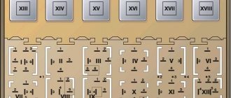
Fig.1. Design and connection diagram of the RS491 (RS491A) turn relay: 1 - adjusting plate; 2 - glass sleeve; 3 - string; 4, 10 — anchors; 5, 6 — contacts; 7 — adjusting bracket; 8 - elastic plate; 9 - core; 11 — support plate; 12 — control lamp; 13 - battery; 14 — ignition switch; 15- direction indicator switch; 16 — signal lamps for direction indicators; 17 — side repeater lamps.
Fig.2.
Diagram of light signaling for turns of a VAZ - 2101 car with a turn relay RS491 (RS491A), where: 1 - signal lamps; 2 — side repeater lamps; 3 — direction indicator switch; 4 — turn relay; 5 - control lamp; VZ - ignition switch. vote
Article rating
Maintenance, repair
Of all the car’s electrical appliances, only power supplies require maintenance:
- Battery (periodic recharging using chargers, monitoring the level and density of the electrolyte);
- Generator (periodic check of drive tension, replacement of worn graphite brushes).
It is also important to monitor the condition of the wire insulation and prevent it from being damaged to avoid a short circuit. Oxidation of contacts often occurs at the wiring junctions, which can lead to failure of electrical appliances
Most of the electrical network components are maintenance-free and must be replaced if they fail. Such elements include light bulbs, small electric motors, switches, relays, fuses, and sensors.
In the starter, generator, electric. In the heater and cooling system fan motors, mechanical breakdowns may occur - wear of bearings, bushings, brushes. All these components are repairable and it is often possible to restore their functionality by disassembling, troubleshooting and installing new parts to replace worn ones.