Logan » Maintenance and repair
Renault Logan 1 has 2 mounting blocks: in the cabin and under the hood. Even a novice car owner will not have any problems with replacing internal elements. The replacement procedure itself does not take more than 10 minutes.
This article will tell you about the fuse layout in Renault Logan 1, decoding and pinout.
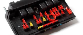
Fuse and relay boxes in the engine compartment
In the first generation Renault Logan, two versions of mounting blocks were installed: prefabricated (vehicles assembled before 05/17/2005) and single (vehicles assembled from 05/17/2005 to 2013).
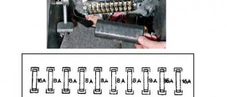
Option 1
It is assembled from 11 small blocks and is divided into two parts, attached to the edges of the battery. The location of the fuses and their explanation are shown in the photo and in the table below.
Circuit breakers
| Small block designation | Element designation | Denomination, A | Protected/maintained circuit |
| 597A | F1 | 60 | Security alarm; Outdoor lighting switch; Daytime Traffic Lighting |
| F2 | 60 | Outdoor lighting switch; Mounting block in the cabin | |
| 597V | F1 | 30 | Relay board power supply |
| F2 | 25 | Injection system | |
| F3 | 5 | Injection system and its computer | |
| 597C | F1 | 50 | ABS |
| F2 | 25 | ABS | |
| 597D | F1 | 40 | High speed electric fan, relay board |
Relay
| Small block designation | Element designation | Protected/maintained circuit |
| 299 | 231 | Fog lights |
| 753 | Headlight washer pump | |
| 784 | 474 | Turning on the air conditioning compressor |
| 700 | Low speed electric fan | |
| 1034 | 288 | Daytime Traffic Lighting |
| 289 | ||
| 290 | ||
| 1047 | 236 | Fuel pump |
| 238 | Injection block | |
| Other (separate relays) | 233 | Heater fan |
| 236 | High speed electric fan |
Option 2
The block is installed in the recess between the left shock absorber strut and the headlight.
Circuit breakers
| Designation | Denomination, A | Protected circuit |
| F1 | 60 | Ignition switch and all consumers powered from the lock; Outdoor Light Switch |
| F2 | 30 | Cooling fan (on a vehicle without air conditioning) |
| F3 | 25 | Fuel pump and ignition coils; Engine management system |
| F4 | 5 | Constant power supply to the engine control ECU |
| F5 | 15 | Not used |
| F6 | 60 | Cabin mounting block |
| F7 | 40 | Power circuits: air conditioning relay K4; relay K3 low speed cooling fan (on a car with air conditioning); relay K2 high speed cooling fan (on a car with air conditioning) |
| F8 | 25 | ABS computer circuits |
| F9 | 50 | ABS computer circuits |
Relay
| Designation | Served consumer |
| K1 | Heater fan motor |
| K2 | Cooling fan motor |
| short circuit | Cooling fan electric motor (for a car with air conditioning - through a resistor) |
| K4 | Air conditioning compressor electromagnetic clutch |
| K5 | Fuel pump and ignition coil |
| K6 | Oxygen concentration sensor (heating circuit); Speed sensor; Fuel injectors; Canister purge solenoid valve; Relay windings K2, K3, K4 |
| K7 (optional) | Headlight washer pump |
| K8 | Fog lamps |
Some tips when working on car electrical circuits
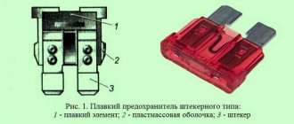
- If it is necessary to remove a burnt-out insert, do not use metal screwdrivers or other objects. Try to avoid them, otherwise a short circuit may occur in the electrical circuit;
- It is not recommended to disconnect the battery terminals while the engine is running and not turned off. If you don't do this, you may pay the price with your voltage regulator and other electronic equipment;
- if there is a need to carry out electric welding work on the car body, then the connecting terminals of the battery and the generator set must be disconnected, and the engine ECU must also be disconnected;
- when the engine is running, you need to be very careful not to accidentally touch the elements of the ignition system and high-voltage wires;
- Another rule that must be followed: it is necessary to periodically inspect the battery terminals and connecting terminals of the wiring for contamination and oxides. If any are found, immediate cleaning should be carried out;
- Before performing any operations on electrical equipment, you should carefully study the circuit diagram to which it is connected to understand how it works.
Violation of the integrity of some fuse links cannot be determined visually. To find out exactly where the short circuit occurred, use a test lamp. How it works? The suspected burnt fuse is removed from the circuit. A lamp is connected in its place. If it starts flashing, there is a short in the main wiring harness. Perhaps the insulation has broken through some of the wires.
Using this test lamp, you can check the electrical circuit for an open circuit. In this case, an additional power source is needed. The contact wires of the lamp are connected to the connecting ends of the circuit. If a glow is observed, it means that current is passing through it. Otherwise, you need to look for the break point.
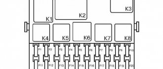
Block in the cabin
It is located at the left end of the dashboard and is closed with a lid.
On its back there are: a diagram of the location of fuses in Renault Logan 1, plastic tweezers and 4 spare fuses with ratings of 5, 10, 15, 30 amperes. There is no relay in the cabin. The explanation of the scheme is given in the table below.
| Fuse designation | Denomination, A | Protected elements |
| F01 | 20 | Windshield wiper; Heated rear window |
| F02 | 5 | Power supply for instrument cluster; Fuel pump and ignition coils; Power supply to the engine ECU from the ignition switch |
| F03 | 20 | Stop lights; Reversing lights; Windshield washer |
| F04 | 10 | Airbag computer; Turn signals; Engine management system diagnostic connector; Immobilizer coils |
| F05-F08 | – | Reserve |
| F09 | 10 | Low beam (left side); Low beam indicator on the instrument panel; Headlight washer pump |
| F10 | 10 | Low beam (right side) |
| F11 | 10 | High beam (left side); High beam indicator on the instrument panel |
| F12 | 10 | High beam (right side) |
| F13 | 30 | Power windows for rear doors |
| F14 | 30 | Power windows for front doors |
| F15 | 10 | ABS ECU |
| F16 | 15 | Driver and passenger seat heating switch |
| F17 | 15 | Sound signal |
| F18 | 10 | Side lights: left side; License plate lighting; Lighting: instrument cluster, controls on the instrument panel, console and floor tunnel lining; Switch box buzzer |
| F19 | 7.5 | Side lights: right side; Glove compartment lighting |
| F20 | 7.5 | Rear fog light lamps and warning light |
| F21 | 5 | Heated exterior mirrors |
| F22 – F23 | – | Reserve |
| F24 | 5 | Electric power steering pump |
| F25 | 5 | PGBN injection system |
| F26 | 5 | Airbag and seat belt pretensioner control unit |
| F27 | 20 | Rear wiper motor; Windshield wiper-wash switch; Headlight washer pump; Reversing light switch |
| F28 | 15 | Interior and trunk lighting lamps; Constant power supply to the head unit for sound reproduction |
| F29 | 15 | Hazard switch; Turn signal switch; Intermittent operation of the windshield wiper; Central locking; ECM diagnostic connector |
| F30 | 20 | Central locking power circuit |
| F31 | 15 | Fog lights |
| F32 | 30 | Heated rear window |
| F36 | 30 | Heater fan |
| F37 | 5 | Electric exterior mirrors |
| F38 | 10 | Cigarette lighter; Power supply to the head unit for sound reproduction from the ignition switch |
| F39 | 30 | Heater fan |
Renault Logan fuse diagram
The fuses and relays of the 2nd generation Renault Logan car perform one of the main tasks - instead of burning out the electrical circuit, they burn out themselves.
Only the relays also switch high currents in the protective casing of the switchboard.
These elements are located in two places in the second generation Renault Logan - in the power unit compartment and in the vehicle interior.
Fuse selection, original and analogue
Fuse table for Renault Logan 2nd generation, article number and approximate cost:
| vendor code | Name | Color | Cost, rub. |
| 243809584R | Block body | 1 900 | |
| 8200248099 | 25a | Grey | 350 |
| 7700410540 | maxi 40a | Orange | 350 |
| 7700410541 | maxi 50a | Red | 270 |
| 7700410542 | maxi 60a | Light blue | 180 |
| 7700410574 | mikro 10a | Red | 90 |
| 7700410576 | mikro 20a | Yellow | 100 |
| 7700410577 | mikro 25a | White | |
| 7700410578 | mikro 30a | White, beige, green | |
| 7700410572 | mikro 5a | Light brown | |
| 7700410550 | mini 15a | Light blue | |
| 7700410553 | mini 30a | Light blue | |
| 7700410548 | mini 7.5a | Brown | |
| 8200253921 | Relay 12v 40a | 2 700 | |
| 8200263342 | Relay 20a (p/t headlights) | 2 300 | |
| 7700844253 | Fan relay, 12v40a | Yellow | 400 |
| 7700414484 | Starter relay, 20a | Black | 1 000 |
Important information: when choosing fuses, preference should be given to original spare parts. However, to save money, similar options are also suitable, but you should find out in advance about the quality and service life of the elements.
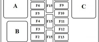
In a second-generation Renault Logan car, fuses and relays are located in two places, namely: in the engine compartment and in the passenger compartment.
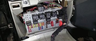
The mounting block in the power unit compartment is located on the left side under the cover. To gain access to the elements, remove the cover.
- Location diagram of the fuse box in the engine compartment:
- Here the fuses are responsible for the following.
- Ef 1. Right windshield heated component.
- Ef 2. Left windshield heating component.
- Ef 3. Anti-lock braking system control unit (50 A).
- Ef 4. Power supply circuits for fuses F28 – F31 in the passenger compartment.
- Ef 5. Power supply circuits for fuses F11, F23 – F27, F34, F39 in the passenger compartment.
- Ef 6. Anti-lock braking system control unit (30 A).
- Ef 7. Heated rear window and exterior mirrors.
- Ef 8. Front fog lights.
- Ef 9. Heated front seats.
- Ef 10. If there is an air conditioner, this is the compressor clutch.
- Ef 11. ECM main relay. Fuel pump relay, fuel pump, fuel quantity analysis device, ignition coil, air conditioning compressor relay winding, electric fan first speed relay winding, electronic engine control unit.
- Ef 12. Power unit cooling mechanism block.
- Ef 13. Power unit control mechanism.
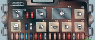
Diagram of the second fuse box of the second generation Renault Logan:
The purpose of the elements is as follows.
- F 1. Electric front window lifts.
- F 2 and F 3. High beam of the left and right headlights, respectively.
- F 4 and F 5. Low beam of the left and right headlights, respectively.
- F 6 and F 7. Dimensions on the right and left, respectively.
- F 8. Electric rear window lifts.
- F 9. Rear fog light.
- F 10. Sound signal.
- F 11. Central locking.
- F 12. ABS system, directional stability and brake signals.
- F 13. Climate control control unit, as well as interior and luggage compartment lighting.
- F 14. Steering angle device.
- F 15. Windshield washer and wiper, reversing light.
- F 16. Audio system, seat belt warning, heated rear window and windshield relay.
- F 17. Daytime running lamps.
- F 18. Brake alert.
- F 19. Control system.
- F 20. Airbags.
- F 21, F 22, F 23, F 28 and F 30. Reserve.
- F 24. Turn signals.
- F 25. Anti-theft system and electrical equipment control sensor.
- F 26. Dimensions, electric external rear view mirrors, turn signals, central locking and hazard warning switch.
- F 27 and F 29. Switches under the steering wheel.
- F 31. Instrument panel.
- F 32. Audio system.
- F 33. Cigarette lighter.
- F 34. Connectors for radio.
- F 35. Heated exterior mirrors.
- F 36. Electric drive of external mirrors.
- F 37. Starter.
- F 38. Windshield wiper.
- F 39. Climate control.
Replacing the fuse box
This procedure is required when the fuses begin to blow. This means that their service life has expired, or the problem is related to contamination, moisture and other factors that lead to rapid wear of the elements of the 2nd generation Renault Logan car.
To replace, the first step is to turn off the powertrain and remove both terminals from the battery. Then remove the fuse box cover. Unscrew the bolts and remove the spare part.
After dismantling, install a new unit.
Important information: if you are not confident in your abilities, it is recommended to contact a service center to repair the damage. Experienced mechanics will carry out the procedure quickly and at an affordable cost.
Source: https://loganlogan.ru/renault-logan-repair/predohranitelej-reno-logan-shema-zamena-i-blok-predohranitelej.html
Removal and replacement process
To replace failed parts, you will need plastic tweezers, included with the car, and a screwdriver with a narrow flat blade.
Under the hood
The procedure is as follows:
- Turn off the ignition and remove the key from the lock,
- Take puller tweezers.
- Open the driver's door.
- Remove the cover from the interior unit.
- Open the hood.
- Remove the mounting block cover by unlatching the latches on the desired side (for machines assembled before 05/17/2005) or by sliding the latches (for machines assembled after 05/17/2005).
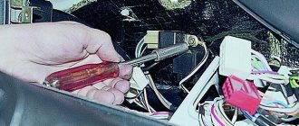
- Using tweezers or your hand, pull out the failed relay or fuse. If this cannot be done, you can use a screwdriver by inserting its tip into the slot on the fuse and pulling up.
- Eliminate the cause of the fuse-link burnout or relay failure.
- Install a new fuse or relay.
- Reinstall the removed parts in their original locations.
Renault Logan fuse diagram
The electrical circuit according to which the Renault Logan provides power to the cigarette lighter unit is very primitive. The standard source sends voltage to the fuse (10A), which is located inside the mounting module.
This fuse box is located in the cabin, or more precisely, above the Renault Logan hood release handle. Wires connect two objects: the mounting block itself and the corresponding socket on the console.
In this article we will tell you where a very important element is located - the cigarette lighter fuse, as well as other fuses and relays, as well as a fuse diagram for a Renault Logan car.
If a malfunction occurs, you should first make sure that the corresponding fuses are intact. Its markings are red and have the symbols “F38”. It is important to remember that there is no cigarette lighter symbol on the surface of the mounting block cover. The cigarette lighter fuse is powered by the audio system.
This forces you to navigate precisely by its designation. Therefore, you can easily find where the very important element, the cigarette lighter fuse, is located, since due to the numerous gadgets connected to it (laptops, smartphones, etc.), these fuses fail more often than others, not only on Renault Logan.
Among the most common causes of block burnout is the fact that a large number of simultaneously functioning energy consumers are connected to the Renault Logan on-board network. If any of the devices consumes a current whose value exceeds 10A, then subsequent burnout is guaranteed.
Here among the leaders is the electric pump. To prevent damage to the unit, the procedure for inflating the wheels should be performed with the audio system turned off, since the radio and the pump are powered through the same circuit.
Before connecting the hose to the nipple, pause, allowing the pump to run idle for a short time.
Another important cause of failure may be the incompatibility of the size of the pantograph plug with the power socket. Loose contact causes increased heating of the terminals. Upon reaching a specific temperature value, the terminals begin to melt and cause a short circuit. In such a situation, replacing a single fuse cannot be done. The entire block has to be replaced.
Location of the “F38” in the mounting block of the 1.4-liter Renault Logan:
Preventive actions
If you don't want to constantly stock up on tons of fuse sets, you should implement a strategy to counteract their frequent failures.
- The first and most common method is to use fuses on an analogue with a higher power. Experts recommend using devices with a power of 15A. The likelihood of burnout is minimized, and damage to the on-board network does not occur.
- The second measure will be the correct selection of the device. The packaging containers of the most diverse products indicate their power consumption. It’s great if they have their own element. To prevent burnout, carefully read the characteristics of the device you intend to purchase. This is a simpler action compared to “uprooting” the fuse from its socket.
- Thirdly, the plug must be connected correctly. Due to its inconsistency with the design features of the nest, the above problems arise.
To ensure correct connection, the location of the contacts must be horizontal, but not vertical (that is, on the sides, but not at the top and bottom). This action will prevent melting of the terminals in the Renault Logan car.
If a malfunction does occur and the fuses become unusable, then the only solution is replacement. The procedure is quite simple. In order to remove the fuses from the mounting socket, it will be enough to pry them with a flat-profile screwdriver.
About security measures
The fuse box is designed to prevent a fire hazard that occurs due to a short circuit in the electrical network of a Renault Logan car. Even the presence of a block does not allow you to be completely insured against trouble.
- Renault Duster rear view camera
- Comparison of Renault Duster and Kia Sportage 2
- Renault Sandero cabin filter replacement
Prevention options
In order not to constantly purchase a large number of fuses, you need to apply preventive measures.
- The most common way to avoid frequent failure of fuses is to replace them with a more powerful element. Experts recommend installing the device at at least 15 amperes. In this case, the likelihood of problems occurring and fuses blowing is reduced significantly.
- Secondly, you need to carefully select devices, since the electrical power is indicated on the packaging of DVRs, car radios and other products used in cars. To avoid blowing fuses, you need to carefully read their technical characteristics and only then connect them to the car’s electrical network.
- The third condition is that it is recommended to connect the plug correctly. Since due to a mismatch between the standards of the plug and socket of the device, certain problems may arise. The plug is connected correctly if the contacts are in a horizontal position, i.e. on the sides (not below and not above!). This arrangement will avoid burnout and melting of the terminals.
But if a problem does arise and the element burns out, then it will have to be replaced with a new one. This procedure is extremely simple; in Renault Logan you can get it out by prying it off with a thin flat-head screwdriver.
About the features of the system design
The design of the fuel supply system to the Renault Logan engine implies the presence of several components through which the fuel-air mixture under pressure enters the combustion chambers of the cylinders. The main elements of this system are:
- gas tank;
- main fuel line;
- fuel rail;
- return line;
- nozzles;
- pressure regulator;
- fuel gasoline pump;
- level sensor and filter.
Sometimes the fuel pump needs to be replaced. The functioning of the system under consideration is subordinated to an on-board computer, which, in real time, based on signals from various sensors, adjusts the operation in order to ensure that the mixture is supplied to the combustion chambers with an optimal ratio of fuel and air.
Fuel pump diagnostics
In order not to make a mistake when buying a new part, you should be sure that it is the fuel pump that is not working. To do this, you will have to carry out a number of diagnostic operations. So let's get started:
- The first diagnostic operation will be to simply turn on the ignition switch. If you turn the key to position No. 2, the fuel pump will create a certain sound that will be heard. If he didn’t appear, then that’s definitely the reason.
- The next step is to examine fuses and relays.
Examine the fuse (F02 (5 A)), which is responsible for the operation of the fuel pump, and determine its functionality. Change if necessary. Location of fuses in the main unit - Now you should diagnose the relay. To do this, you need to turn the ignition key several times, if it clicks, then everything is fine. It will not be possible to check the relay using diagnostic programs that work through the connector.
- If all of the above elements are intact, then the fuel pump is “dead” and must be replaced.
Brake light faults
View of the additional brake light from inside the car
If you decide to start or continue driving a car when the brake lights are faulty, this means exposing not only yourself, but also all other road users to danger. Therefore, lamps should be periodically monitored and maintained.
Among the problems, the most common cases are:
- During braking, the brake light does not work on one side.
- When braking, the brake lights on both sides do not work.
- Additional signal light does not work
Diagnostic and repair methods
Since the functioning and performance of these outdoor lighting elements directly depends on the performance of the vehicle’s electrical network, it is necessary to pay close attention to its condition. If all the brake lights on your car stop working at once, the reason for this is most often the failure of fuse F3 (for the passage of current with a force of no more than 20A) located in the Renault Logan interior fuse box
If all the brake lights on your car stop working at once, the reason for this is most often the failure of fuse F3 (for the passage of a current with a force of no more than 20A) located in the fuse box of the Renault Logan interior.
The location of the fuse we need is marked with a red marker.
This element is part of the direct power supply circuit to the brake lights. You can check the serviceability of the circuit using a known good fuse or using a tester (multimeter). If such manipulations do not bring the desired result, and the lights still do not work, then the search for the fault must be continued. The next step in the repair will be to check the wiring for evidence of breakage or chafing of the wire in the circuit.
Next, an element that can also cause a malfunction is the brake lamp switch on Renault Logan, which is installed on the bracket with the pedals. For more effective diagnostics, it is best to remove it from its seat. This work is carried out in the following order:
- Since the circuit of this sensor is constantly energized, you should disconnect the negative terminal from the battery.
- Next, remove the connector with wires.
- In order to pull it out from its place of fixation, you need to turn the sensor body 90 degrees and slowly pull it towards you until it is completely dismantled.
To check the sensor, you can use a tester and measure its resistance, or connect a known-good sensor. Checking the device with a tester is very easy; we connect the tester wires to the sensor connectors, and use our hands to operate on the protruding rod. A working device will thus show its functionality, but a broken one must be replaced.
The next step is to check that the mains voltage is reaching the working sensor. We connect the battery back to the network and use the equipment to check the voltage in the sensor terminals. If the result is positive, we put everything back together in reverse order and proceed to direct diagnosis and replacement of the brake light bulbs.
Key-dop
- When the ignition key is turned to the 2nd position, the fuel pump relay is turned on, which operates for several seconds, providing the required pressure in the fuel rail. The engine can then be started. This is the normal operating mode of the system.
- When the Renault Logan engine starts, the relay is activated again, ensuring that the pump operates continuously throughout the entire engine operation. Thanks to this, fuel is supplied to the ramp continuously through the fuel pump. In it, the regulator ensures that constant fuel pressure is maintained, eliminating the formation of excess (it returns to the tank via the return line).
- If interruptions occur in the operation of the motor, the first diagnostic measure will be to check the integrity of the pump fuse and relay. And if a breakdown is detected, the fuel pump needs to be replaced.
Renault Logan Loganenish Logbook Cigarette lighter burned out
Nexia fuses Quite recently I had some trouble. The radio stopped working, and so did the cigarette lighter. On the Logan there is one fuse for the cigarette lighter and the radio, I went and looked at the burnt fuse, changed it, decided to turn on the radio, but it still doesn’t work. The cigarette lighter doesn't turn on either. I went to the fuses again and it turned out that the fuse I had just inserted had burned out again. Look at the cigarette lighter and it has melted on one side inside.
Melted cigarette lighter
Without thinking twice, it was decided to remove the cigarette lighter (pull out the block from it) so that nothing would short-circuit.
But here the first set-up awaited, as you know, on Logan a lot of things are twisted on torexes, and I didn’t have such keys. Thanks to my colleague. who drives an Opel Astra of previous generations, it turns out that everything is also on Torex and he helped me out with the keys. First, he unscrewed two bolts under the cup holders in the front.
Then one bolt at the feet of the rear passengers under the plastic latch.
After that, I pulled out the lower part of the floor tunnel and pulled it through the handbrake and removed it.
Floor tunnel without bottom
Stand number two was waiting here; to remove the upper part, you had to unscrew the nut securing the upper part to the floor. It was impossible to get to it with any socket wrench, and I didn’t have a wrench with heads. I had to go back to the mercy of my colleague in the Opel. And armed with a twelve-point head and a wrench, the vile nut was defeated
Nasty nut
After this, the upper part was safely removed, the cigarette lighter can be turned off.
Cigarette lighter socket Under the removed top of the floor tunnel, a Dacia computer manufactured by Bosch was discovered. Here it turns out to be where it is located.
We're nowhere without Bosch. After that, the cigarette lighter socket was removed and everything was put back in place. The fuse was replaced (instead of 10 I put 15 on the forum, Logan swears that nothing bad will happen from this and I am inclined to believe them), the radio started working safely.
Now I’ll worry about buying a new cigarette lighter for the car, but having already called all the stores selling Logan spare parts, I discovered that no one has such a simple thing.