You have to remove the relay and fuse box on Lada Kalina and Grant cars if it is replaced with a new one, or to gain access to other parts, for example, the central locking control unit. Removing the mounting block with your own hands is not difficult if you know the location of all the fastening screws.
Required
: small ratchet with a cross bit.
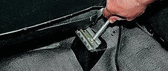
- Remove the steering column cover (lower the steering column clamp downwards and remove the fastening screws).
- Remove the cover of the mounting block (snap off the cover in the sequence: 1, 2, 3, 6, 4 and 5).
- Remove the right mounting block screw using a small ratchet with a Phillips bit.
The process of removing the fuse box is also shown in the video:
Let us remind you that you can find the design of the relay and fuse box here (for Lada Kalina and Lada Granta).
In a Lada Granta car, the block where the fuses are located is a very important element that ensures the safety of the on-board electrical network. Without this unit, any pantograph can be damaged if a short circuit occurs in electrical lines. Among the likely consequences of such unpleasant phenomena as a short circuit, fire of wiring is present in the foreground. In view of this, the process of installing the fuse box is of particular importance. The driver must know where the fuses are in his car.
About fuses in Grant
Sometimes failures of elements in the vehicle's electrical on-board network occur. For domestic models, this malfunction is much more relevant in comparison with foreign analogues. The causes of damage to the electrical network can be very different. Among the most common factors causing blackouts is the usual overvoltage. Most likely, after this phenomenon, the owner will need to replace the corresponding fuse. A painfully familiar model, the Lada Granta, can serve as an example.
In the car we are considering, the lion's share of electrical circuits and current collectors is protected by fuses. We should not forget about the lack of protection for three nodes:
- battery charging circuits;
- generator electrical circuit;
- starter.
Recommendations for use
Set of protective elements for a car
- We strongly recommend that when operating a Lada Granta car, you have spare parts on hand in the electrical fuse box.
- The magnitude of the current on the protective elements differs according to the color of the shell.
- Often the reason for the failure of any consumer may not be the fusible elements. Before changing the fuse, check the condition of the entire electrical circuit. Proceed to replacing the fuse only after identifying and eliminating the cause of its blown.
- Some consumers are powered through the cigarette lighter socket and if the plug does not match it, the fuse element may burn. In this case, it is recommended to replace the plug with a suitable one.
- A common cause of a blown fuse is moisture ingress due to seams and process holes not being sealed properly. In this situation, you need to carefully inspect the entire electrical circuit route so that this malfunction does not happen again.
- Be careful when working with electrical equipment. Change protective elements and relays only after making sure that the engine is turned off and the ignition is turned off.
Sorry, there are no surveys available at this time.
Features of the first mounting block
Once you know where the blocks are, you can talk about their features. Another significant difference between the Lada Grant and representatives of previous generations is its numerical composition. Now it is equal to 32 units. For a detailed understanding, you will need to carefully familiarize yourself with the block diagram. For example, fuse F1 has a function to protect the circuits of such current collectors:
- ignition coils;
- nozzles;
- motor and fan control unit.
Element F2 is responsible for the safety of the electrical power window mechanism circuits.
F3 and F4 respectively “monitor” the safety of circuits belonging to:
- hazard warning lights and windshield wipers;
- airbag.
Elements F9 and F10 are “entrusted” with controlling the wiring to the side lights.
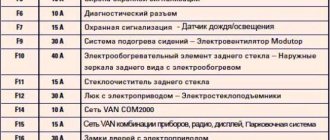
It is important to remember that each safety element has a current limit that it can withstand.
- F8, “standing guard” of the rear window heating circuit, is designed for a maximum of 30 Amps;
- F6, which controls the operation of the reversing light, can only withstand 7.5 A.
It is easy to guess that these values of this parameter are directly dependent on the required electrical consumption of a particular pantograph.
To familiarize yourself in detail with the circuits and the fuses that protect them, it is recommended to resort to the diagram (Fig. 3).
If we move on to the consideration of relays, then in the Lada Granta they are present in the amount of 12 units. These elements are designed to maintain the functionality of many current collectors (heating system fan, starter, electric fuel pump, etc.).
Types of fuses
There are two types of devices installed in a Korean car. The main ones are responsible for the operation of wires with a high current layer, the typical ones are responsible for the operation of wires with a low current level. In total, a Korean foreign car produced after 2011 has 46 fuses, 16 in the interior, and 30 under the hood.
Element ratings range from 10 A to 80 A. Small fuses can be purchased in blocks so that you always have a replacement if they fail. A burnt-out part can be recognized by a slightly melted plastic eyelet located on the top and side of its body.
The location of each element in the block does not differ for cars produced in 2011, 2012, 2013, 2014; it will be standard everywhere. The fastest-melting typical devices are located mainly in the interior torpedo unit, while the more powerful ones are located under the hood. The process for replacing them is almost identical, with minor exceptions.
The nuances of manipulating the power unit
To correctly replace an element in a LADA Granta, you should use specific rules and know where the so-called fuse box is located. If a burnout occurs, do not rush and replace the failed part with an analogue one. It is recommended to check the serviceability of the current collectors protected by this fuse.
We replace the element that contains the fuse box in strict accordance with the requirements of the circuit. There is no need to resort to installing fuses designed for a higher current limit, as this can cause a fire. It is also necessary to disconnect the negative voltage from the battery.
How to find out which fuse has blown
On each of the fuse blocks, or rather, on their covers, there is a diagram placed there by the manufacturer. Using it, you can easily find out which circuit is responsible for which protection device. The cover can be removed by hand - no special tools are required.
The non-working circuit element should be determined based on the nature of the problem. There are two ways to verify that the fuse has blown. If you have a multimeter, it will be safer to use it. To do this you need to do the following:
- turn on the ignition;
- set the tester to sound;
- Check each fuse in turn by touching their contacts.
The presence of a buzzer allows us to speak with confidence about the serviceability of the fuse.
If you don’t have a voltmeter, you can do without it, although it will take a little more time. You will have to pull out each surge protection element and carefully inspect it. There is a fusible insert inside it - its integrity indicates serviceability.
We act in the salon
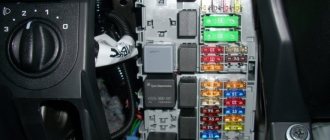
- The fuse box is located on the left side of the instrument panel. Remove the cover with the outdoor lighting mode switch integrated into it. If the work is carried out on the LADA Granta “Lux” and “Norma” modifications, then do not forget about the need to disable the button used to unlock the trunk lock.
- Armed with the diagram, we determine whether the cigarette lighter fuse or the fuel pump fuse has become unusable, and so on. We look at the integrity of the thread and draw the appropriate conclusion. If the element is unfit, then we replace it with a new analogue by fixing it in the mounting socket. We repeat this action with the entire list of blown fuses.
- We connect the “minus” back to the battery and check the functioning of the electrical unit in which the fuse was replaced.
The process of replacing the specified elements, which contain the fuse block, of the engine compartment of the Lada Granta is implemented in a similar way. The cover on the safety module is removed using a simple action - just pull it up and quietly replace the marked elements.
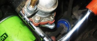
Location of fuses on Priora
The fuses on the VAZ 2170 and its modifications are concentrated in different places as follows:
- In the interior mounting block, which is hidden behind the dashboard cover opposite the driver’s left foot;
- In the additional relay and safety block on the right under the lining of the floor tunnel near the navigator's left leg;
- In the main fuse block under the hood near the expansion tank. It is there that the most powerful safety system is located, designed to ensure the operation of power electrical circuits;
- In the relay and safety block of the air conditioner next to the front left shock absorber strut cup.
Of course, each block contains fuses and/or relays responsible for the operation of a particular electrical system, so you need to take a closer look at where and which of them are located.
Relays and fuses of the mounting block in the passenger compartment under the dashboard
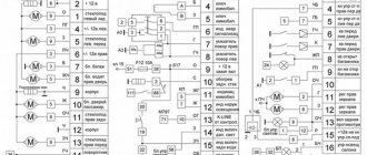
So, under the dashboard cover we will find the interior relay and safety unit, also called the “black box”. There are no such number of relays and fuses anywhere else, so most of the problems are associated with this relay-fuse group. It is also the subject of greatest interest. Relays are marked with the letter K and a digital designation, which for this block has the following interpretation. (Indicated in Fig. 1)
In addition, the interior mounting block contains fuses, marked with the letter F, which protect the following circuits (Indicated in Fig. 2):
The wiring diagram for the interior mounting block can be seen on the back surface of the cover that covers it.
Safety relay group of an additional block in the floor tunnel
This block is called additional and contains relays (marked with the letter K) and fuses (F) of such technical systems (See Fig. 3):
Cabin fuses for VAZ 2114 - decoding of circuits and areas of responsibility
A separate fuse panel for the cabin unit is designed to control secondary circuits of electrical equipment. The main task of the module is to relieve the engine compartment and minimize the likelihood of breakdowns due to board overload.
In 90% of cases, the mounting block is equipped with a small set of inserts. This is due to the intended purpose of the device. In fact, such modules are installed here.
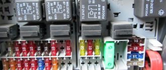
In the mounting panel, the control relays are arranged in sequence from left to right:
- Control of the fuel pump power cores. From here voltage is supplied to the main line.
- Main engine relay. Responsible for powering the ECU and parallel circuits of the primary control system of the vehicle.
- Breaker element for the power cores of the main fan of the engine cooling system.
There is also a similar number of fuse links. Each element works in tandem with a relay and is responsible for protecting the system from overload:
- F 1 – VAZ 2114 fuel pump fuse, is responsible for monitoring the correct supply of voltage to the line;
- F 2 – fuse VAZ 2114 injector 8 valves, responsible for controlling the voltage of the car’s main circuit;
- F 3 – fuse link going to the electronic control unit.
Types of fuse blocks installed in Lada Granta (until 2016)
Electrical circuits protected by fuses located in the fuse box and car interior relays of standard/luxury versions
| № | Denomination | Protected Circuits |
| F1 | 15A | Ignition coils |
| Injectors | ||
| Engine Control System Controller | ||
| F2 | 25A | Central body electronics unit |
| Driver door module | ||
| F3 | 15A | Automatic transmission control controller |
| Automatic gearbox control drive | ||
| F4 | 15A | Airbag system controller |
| F5 | 7.5A | Terminal 15 devices |
| F6 | 7.5A | Reversing light |
| Automatic transmission control controller | ||
| Safe parking system control unit | ||
| F7 | 7.5A | Canister purge valve |
| Mass air flow sensor/pressure sensor | ||
| Phase sensor | ||
| Oxygen concentration sensors | ||
| F8 | 25A | Rear window defroster |
| Heated exterior mirrors | ||
| F9 | 5A | Side lights on the starboard side |
| F10 | 5A | Left side marker lights |
| Illumination of instruments and keys | ||
| License plate lights | ||
| Trunk light | ||
| Glove box light | ||
| F11 | 5A | Rear fog lights |
| F12 | 10A | Low beam, right headlight |
| Electrical corrector for right headlight | ||
| F13 | 10A | Low beam, left headlight |
| Left headlight electric corrector | ||
| F14 | 10A | High beam, right headlight |
| F15 | 10A | High beam, left headlight |
| F16 | 10A | Right fog lamp |
| F17 | 10A | Left fog lamp |
| F18 | 20A | Front seat heaters |
| Cigarette lighter | ||
| F18** | 10A | Cigarette lighter |
| F19 | 5A | Anti-lock brake control unit |
| F20 | 15A | Sound signal |
| F21 | 10A | Fuel pump |
| F22 | 25A | Windshield washer |
| Central body electronics unit | ||
| Rear window washer | ||
| Rear window wiper | ||
| F23 | 5A | Instrument cluster |
| Diagnostic connector | ||
| F24 | 7.5A | A/C compressor clutch |
| Automatic climate control system controller | ||
| F25 | 7.5A | Brake lights |
| F26 | 10A | Central body electronics unit |
| F31 | 25A | (for the front function unit AVAR) / F27 (for the front function block Delphi) Anti-lock brake system control unit |
| F32 | 30A | (for the front unit AVAR) / F28 (for the front unit Delphi) Electric heater fan |
| Automatic climate control system controller |
* A set of fuses is indicated for the maximum configuration of the “luxury” version (depending on the set of options, individual fuses from this set may not be used in other configurations).
** Fuses, the rating of which may vary in different vehicle configurations depending on the set of options.
Electrical circuits protected by fuses located in the fuse box and the standard car interior relay
| № | Denomination | Protected Circuits |
| F1 | 15A | Ignition coils |
| Injectors | ||
| Engine Control System Controller | ||
| F2 | 5A | Daytime Running Lights |
| F3 | 10A | Alarm |
| F4 | 15A | Airbag system controller |
| F5 | 7.5A | Terminal 15 devices |
| F6 | 7.5A | Reversing light |
| Direction indicators | ||
| F7 | 7.5A | Canister purge valve |
| Mass air flow sensor/pressure sensor | ||
| F7 | 7.5A | Phase sensor |
| Oxygen concentration sensors | ||
| F8 | 25A | Rear window defroster |
| F9 | 5A | Side lights on the starboard side |
| F10 | 5A | Left side marker lights |
| Illumination of instruments and keys | ||
| License plate lights | ||
| Trunk light | ||
| Glove box light | ||
| F11 | 5A | Rear fog lights |
| F12 | 10A | Low beam, right headlight |
| Electrical corrector for right headlight | ||
| F13 | 10A | Low beam, left headlight |
| Left headlight electric corrector | ||
| F14 | 10A | High beam, right headlight |
| F15 | 10A | High beam, left headlight |
| F16 | ||
| F17 | ||
| F18 | 15A | Cigarette lighter |
| F19 | 20A | Door locking motors |
| F20 | 15A | Sound signal |
| F21 | 10A | Fuel pump |
| F22 | 15A | Windshield washer |
| Windshield wiper | ||
| Rear window washer | ||
| Rear window wiper | ||
| F23 | 5A | Instrument cluster |
| Diagnostic connector | ||
| F24 | ||
| F25 | 7.5A | Brake lights |
| Interior lighting | ||
| F26 | ||
| F31 | 30A | (for the front unit AVAR) / F27 (for the front unit Delphi) Power windows for front doors |
| F32 | 30A | (for the front unit AVAR) / F28 (for the front unit Delphi) Electric heater fan |
Replacement
Before replacing fuses, you must turn off the ignition and disconnect the battery. This will avoid electric shock.
How to remove a burnt one? The block itself must have special pliers for removing non-working protective equipment (they are supplied by the manufacturer along with the machine). It is better to insert a new one with their help as well. At the same time, it is important to ensure that it matches the previous value.
In a situation where there is no suitable fuse on the farm, a temporary jumper will help. Any copper or aluminum wire of sufficient cross-section will do for it. If necessary, it can be twisted several times.
If the fuse sparks when you turn on the power, then most likely there is a short circuit somewhere. You need to check all the contacts and wires coming from it. Sometimes it is necessary to remove the fuse box. To do this, you must first disconnect the negative terminal from the battery. Next, connectors with wires are disconnected in the cabin - first remove the top one. The block itself is held in place by nuts, which will need to be unscrewed with a 10 mm socket wrench. Then all that remains is to remove the bottom four pads and pull out the entire assembly. There is no need to be afraid of mixing them up during assembly, as they simply will not fit into the “non-native” socket.
Replacing the main fuse - UAZ Patriot, 2.7 l., 2022 on DRIVE2
Hello everyone! So I was not spared the problem of burning main fuse contacts (described here www.drive2.ru/c/536767284102835476/) The solution to the problem is obvious - replacing the fuse.
Some find a way out of the situation by bending the clamps more tightly, or by applying battery terminal grease to the contacts. I consider this a half measure.
Having smoked the forum and taking on board the advice of experienced people, a BRP-4 unit, a meter of copper wire, and several terminals were purchased at the GAZ store
Block with burnt contacts. Three power fuses 60A, 40A, 60A - removed
Using a 10mm wrench, unscrew the M6 nut and remove the red power wire coming from the battery. Using wire cutters we bite off three thick wires that protect our fuses (pink, brown, red)
We take a new BRP-4 block, install fuses of the rating we need (60, 60, 40, 40 reserve). We power the block with three wires (you can use one thick one, but I didn’t find it)
Having tried to cram three terminals onto one stud and realizing that nothing would come of it, I bit them off and soldered three wires into one terminal. Later I will replace this pigtail with one thick wire.
We solder the terminals to the previously bitten off wires that go to consumers
We power the BRP-4 from the old unit. Don’t forget to return the thick red wire from the battery there.
We install wires going to consumers.
Having done all this work and read the report from the outside, here is what I would like to advise: 1. Instead of a pigtail of three red wires, it is better to install one thick one.2.
It is better to increase the wires to consumers (red, pink, brown) by 30 centimeters and throw each one into a corrugation. Then it will be possible to place the BRP-4 somewhere on the engine shield or fender liner.
Now, due to short wires, it just lies on the cover of the old unit.
Something like this. Sincerely.
Price: 500 ₽ Mileage: 42,000 km
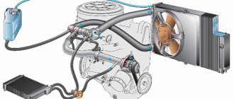
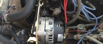
What to do if charging is lost?
If the vehicle is equipped with a G-222 generator device and the generator has lost charging, it is necessary to diagnose the connections in the fuse box. The test is performed using a tester. Below is a list of connections that are subject to diagnostics:
- Sh4-1 - Sh11-4;
- Ш1-6 - safety device number 9 - Ш11-3, most often the reason lies in the rupture of this connection;
- Ш1-4 - Ш10-1;
- Sh5-3 - Sh10-7;
- Ш1-6 - safety element number 10 - Ш4-1.
If the machine is equipped with a 37.3701 generator device, then only the last three circuits are diagnosed:
- Ш1 — brown connector, located on the power supply unit on the interior side;
- Ш4 - blue connector, also located in the cabin;
- Ш5 — yellow connector, in the passenger compartment;
- Ш10 — brown connector, located in the engine compartment;
- Ш11 - yellow connector in the engine compartment.
Afterword
Car owners whose cars keep melting fuses should be sure to check all installed wiring at the first opportunity. Very often this problem is evidence of serious damage in one or more circuits.
To do this you will need detailed:
- electrical circuit;
- pinout;
- tester.
If you lack the necessary knowledge, it is better not to undertake repairs yourself, but to entrust this task to professionals. The fee for their services, of course, can be quite high, but eliminating the consequences of unqualified intervention will cost much more.
VAZ 2114 fuse blown, what to do
Periodically, voltage surges or other failures occur in the vehicle's electrical circuit. This leads to an overload in the circuits and the fuse link is destroyed.
If the breakdown is caused by a momentary failure, it is enough to replace the damaged element and everything will be fine. In the case of a larger defect, the new element will burn out as soon as the car starts. To fully diagnose the system and troubleshoot the problem, you will need to look at the entire line from the fuse to the consumer.
Important!
It is recommended to remove the fuses of the VAZ 2114 injector 8 valves only with special pliers or tweezers. From swinging to the sides, the thin legs of the part may break off.
Knowing the source of the problem will help make the search easier. Failure of the fuse element only occurs when there is a serious increase in voltage within the network, which is caused by a short circuit or system failure of the ECU.
The sequence of actions looks like this:
- remove the damaged element from the socket;
- find the corresponding wire on the back of the diagram;
- move along the highway to the consumer;
- detected damage must be eliminated; if the powered unit itself is damaged, replacement is carried out with a known good one.
Removal and replacement instructions
All car mechanics, without exception, recommend disconnecting the “-” terminal of the battery when working with the vehicle’s electrical equipment.
Preparation
Work on replacing electrical fuses or relays can be carried out anywhere. The main thing is that the place should be well lit. Before starting work, be sure to turn off the car.
Video about replacing the fuel pump fuse on a Lada Granta - to help you.
The work of replacing fuses in the cabin and engine compartment is almost identical. With minor differences.
Cover removal diagram
- Let's start with the first one. To gain access to the fuses and relays located to the left of the driver's feet, you need to remove the cover.
- This must be done according to a certain scheme. First you need to pull the cover by the lower left corner, it is designated as number 1 in the diagram. Next, release the left locking point. Then the middle one at number 2. Next are points 3 and 6. Now all that remains is to free the top points 4 and 5. The entire cover has been removed.
- Visually inspect the block. There should be no burning or melting in it. There should also be no burning smell.
- In the decoding we find the consumer we need and according to the diagram we find its location.
- Using tweezers located in the block, remove the problematic element. We inspect it visually or check it using a device.
- If it is burnt out, then we put a new one in its place.
- The cover of the interior unit is installed in the following order: first of all, you need to snap the right part, then the bottom, and finally the top. It is necessary to ensure that the fastening parts of the cover and the latches match exactly.
The request returned an empty result.
- If the element we need is located in the engine compartment, then we proceed somewhat differently, namely, we open the hood itself.
- Find where the block is located.
- Slide the cover up and remove. We determine the burnt out element, just like in the cabin unit.
- We put the cover in place.
- Connect the “-” terminal of the battery.
- Turn the ignition key.
- If the consumer earns money, then everything is in order.
The request returned an empty result.
If the fuse blows again, the problem may be more serious and you will need to call a professional to help.
Where are the devices located and what are they responsible for?
To begin with, we suggest finding out which fuses and relays are responsible for what, what the electrical pinout of devices on the injection and carburetor VAZ 2107 is. The main part of the parts used are installed in the main device, which is located in the engine compartment. The shield is located directly under the windshield, opposite the passenger seat.
Domestic "Sevens", be it a carburetor or an injector, can be equipped with two types of devices - old and new. Accordingly, the description and diagram of electrical equipment in them will differ slightly. Old-style devices were used on cars of early years of production, new ones were used on later versions.
If we talk directly about the injector and carburetor, the electrical circuit of the devices does not depend on the type of fuel supply system. That is, both carburetor and injection versions of cars can be equipped with new and old units. In versions of cars released later, the unit can be installed inside the car under the glove compartment.
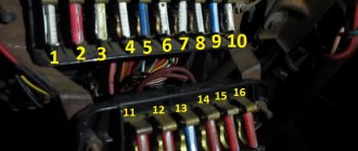
Old type
Old style block diagram
| № | What is it used for? |
| 1 | This component is designed to protect the electrical circuit of the reversing headlights, the heater motor, the dashboard light, and the rear window heating system relay. |
| 2 | Necessary to protect the windshield wiper motor, windshield cleaning system and optics, if provided by the manufacturer. |
| 3, 4 | Auxiliary connectors can be used when adding new devices. |
| 5 | Operation of the rear window heating system. |
| 6 | Designed to ensure the operation of the cigarette lighter. Sometimes this fuse is responsible for the radio, depending on the car. |
| 7 | The device is used to ensure uninterrupted operation of the motor of the ventilation device cooling the radiator, as well as the horn. |
| 8 | Emergency light signaling. |
| 9 | Uninterrupted operation of anti-fog optics. In some "sevens" this fuse is responsible for the operation of the generator voltage regulator. |
| 10 | The element is responsible for the functioning of the instrument cluster, the low battery indicator on the combination, as well as other light bulbs. |
| 11 | Stop lights, sources of internal light of the car body. |
| 12 | High beam headlight, right, activation coil of the optics cleaning system relay. |
| 13 | High beam headlight, left, light bulb on the control panel for turning on the high beam headlights. |
| 14 | Side lighting, license plate light indicator, under-hood light. |
| 15 | Dimensions, light of the instrument panel, glove box, cigarette lighter. |
| 16, 17 | Low beam safety element. |
| 18 | The device is designed to protect the electrical circuit of low-beam headlight bulbs. |
| 19 | This element is necessary to protect the circuit of high beam optics bulbs. |
| Reserve socket | Used to connect the engine fan motor relay in vehicles manufactured before 2000. |
| 20 | Provides the functionality of a sound signal (beep). |
| 21 | Necessary to ensure the operation of optics cleaning systems if the machine is equipped with a washer. |
| 22 | Responsible for the operation of the rear window heating system. |
New type
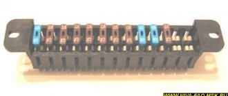
New type device
Purpose of elements in a new type of device
Below is a table describing the relays marked in the diagram with numbers 1-6.
| Number | Description |
| 1 | Provides functionality of the glass heating system. |
| 2 | This relay is used to protect the electric motor of the optics cleaning system. Not installed on all vehicles. |
| 3 | Provides steering horn functionality. In the indicated diagram, there is a plug at the installation location of the device. |
| 4 | Necessary to protect the power unit fan motor. If the relay breaks down, there is a possibility of overheating of the power unit. |
| 5 | This device provides the functionality of high beam lighting sources. |
| 6 | Low beam headlight circuit protection relay. |
Injector
The design of the injection power supply
As we have already reported, the injection versions of the “sevens” have a fuse block similar to carburetors. The difference is that injection cars are additionally equipped with a relay unit, which is located in the car interior under the glove box.
| Number | Purpose |
| F1 | Necessary to ensure the functionality of the main relay. |
| F2 | This relay is designed to protect the ECU from power surges. |
| F3 | Used to protect the car fuel pump circuit. If the element fails, the car owner will not be able to start the engine. |
| R1 | Main relay. |
| R2 | A device used to ensure the operation of the fuel pump. |
| R3 | Engine radiator fan safety element. |