Design and features of the VAZ 2107 injector
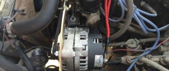
General view of the engine compartment of the VAZ 2107. It is immediately clear that there is no distributor and carburetor.
The VAZ 2107 was not always “injected”. For many years the engine was carburetor. Only since 2006, for the production of VAZ for the domestic Russian market, the engine acquired a forced fuel injection system. The meaning of those innovations was simple - compliance with already accepted Euro 2 standards, which European cars have complied with for many years. The total power of the unit with the new power system was 50 kilowatts. The characteristics of the engine with the new fuel injection were as follows:
- Usage mode in the city – 8.5 liters 100 km;
- Fuel consumption at a speed of 90 mph – 6.9 – 7.0 liters 100 km;
- Consumption at a speed of 120 mph is about 9.1 liters.
The plant guaranteed these characteristics for the VAZ 2107 injector when using gasoline type A - 95. No other type of gasoline was provided for the calculations. The point of converting from carburetor injection to electronic injection was that constant adjustment and fine-tuning of the injection was not required, as with an injection engine. The device is such that the idle speed indicators do not “float”.
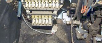
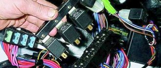
The device shown is a control unit, “microprocessor brains.”
The block takes into account the indicators of those sensors that are necessary for the normal operation of injection injection, namely:
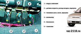
- Throttle position sensor - the device is a resistor of variable capacity, which depends on the degree of pressing the gas pedal. There is no similar equipment in Zhiguli cars, but there is plenty of radio receivers.
- Crankshaft position sensor (that is, cylinder operation). According to the readings of this sensor, the operation of the electronic processor is completely synchronized with the crankshaft speed. This is the "reference clock speed".
- An indicator of the saturation of a mixture with oxygen. This device is located on the exhaust gas pipe, and uses feedback to control the amount of incoming fuel in the mixture, since fuel, when burned, consumes oxygen. The indicators of those processes are completely interrelated. In the figure, the exhaust pipe and sensor are connected by a weld, which means that the exhaust system has most likely been repaired.
- MAF (mass air flow sensor). It is mounted on the “air” body. Its task is to accurately determine the amount of air that enters the intake manifold, and therefore the characteristics of the combustion mixture.
The sensors described above relate exclusively to the injection system, and they are not available on carburetor versions of the “seven”.
Naturally, “there is no smoke without fire.” Therefore, along with many advantages, VAZ 2107 equipped with fuel injection also has certain “cons”.
Disadvantages of an injection engine;
- High requirements for fuel quality and octane number;
- The catalyst installed “under the bottom” of the car significantly reduces the ground clearance, depriving the “Seven” of some off-road advantages over the “puzoterki”;
- More complex engine repairs and difficult access to engine compartment parts.
- In order to find a malfunction in the injection system, special instruments are needed;
- In general, the “injector” is more capricious. So, for example, the opportunity to light a cigarette for a friend may result in the engine stalling. The reason is a malfunction of the “electronic brains”.
But the advantages completely compensate for these disadvantages, since injection injection allows you to save fuel, makes cold starting of the engine easier, and there is no need to “tinker” with the carburetor. A car with such an injection will serve you for many years with proper care.
This information will be useful to you
Did you read to the end? How was your first virtual acquaintance with the car? Do you think everything is very complicated and unclear? Don't worry, everyone started out this way. Studying the topic and practicing will yield positive results. You will learn how to maintain your car yourself. At first it will simply be checking the fluid level, inspecting the general condition of the engine and its components. You will learn to identify leaks, the condition of hoses, simple technical breakdowns, for example, loose battery terminals or loose clamps. Further more and in the end, before you have time to blink your eye, you will learn how to change the oil in the engine, gearbox and replace the brake pads yourself. Who knows, maybe you will like servicing the car so much that you will learn how to rebuild the engine and suspension? All in your hands!
Until then, if you are interested, start studying the operating instructions, read the forums and ask an experienced friend to show you the basics of maintenance using your car as an example.
Remember that it is necessary to regularly check the level of technical fluids: engine oil, power steering, and, if necessary, inspect the oil level in the gearbox. Don’t forget to keep an eye on the coolant temperature; engines really don’t like overheating. Monitor the correct tire pressure, wheel alignment (it is advisable to check the wheel alignment once every six months) and battery charging (ideally, change the battery for a new one every three years).
Tip: When replacing the battery, first remove the negative terminal, then the positive one. The terminals are placed in the same way, first plus to plus, then minus to minus.
Keep a journal in which all work performed on the machine will be entered. Note the mileage at which they were performed. After all, only with regular, proper maintenance will your car last longer and bring you joy rather than disappointment from sudden breakdowns.
Related posts:
- Which vessel contains hot water?
- Which studded tires to choose for the winter
- Daewoo Nexia 16 valve speedometer does not work
- Types of highway pavement
Did you like the article? add it to your bookmarks so as not to lose it - PRESS “Ctrl + D”
| 7 Radiator cap (DO NOT open it when the engine is hot! To check for pressure before unscrewing, squeeze the radiator hose with your hand. If the hose is elastic or hard, there is pressure in the system, DO NOT open the cap!) |
| 8 Engine oil filler cap (motor oil is poured here) |
| 9 Engine oil dipstick (turn off the engine before checking the oil level and wait 10-15 minutes. Now you can start checking. Keep low within min and max risk limits) |
| 10 Components of the air conditioning system (it is strongly NOT recommended to climb into it without knowledge. The compressor has freon pumped under pressure) |
| 11 Battery |
| 12 Information labels (in these labels you can find out information about your car model) |
| 13 Hood latch |
| 14 Drive belt (drives engine pulleys) |
| 15 Generator (produces energy to run the engine and charge the battery) |
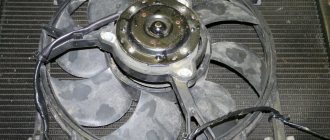
| 16 Fan shroud |
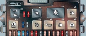
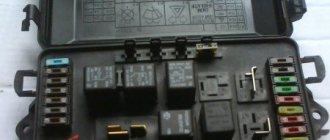
| 6 One of two fuse blocks |
| 7 Radiator cap (DO NOT open it when the engine is hot! To check for pressure before unscrewing, squeeze the radiator hose with your hand. If the hose is elastic or hard, there is pressure in the system, DO NOT open the cap!) |
| 8 Engine oil filler cap |
| 9 Engine oil dipstick |
| 10 Air conditioning system components (Freon. Danger! Pressure. Leave service to professionals) |
| 11 Windshield washer fluid reservoir |
| 12 Information labels (information about the types of spark plugs, air conditioning systems and other systems of your car model) |
| 13 Hood latch |
| 14 Access to shock absorbers |
↑ Engine
The car is equipped with a gasoline, four-stroke, four-cylinder, in-line, eight-valve engine with an overhead camshaft.
- The power supply system is carburetor.
- The operating order of the cylinders is: 1–3–4–2, counting from the crankshaft pulley.
↑ Differences between VAZ-2103 and VAZ-2106 engines
The VAZ-2103 engine differs from the VAZ-2106 engine in its smaller cylinder diameter (76 mm versus 79) and, accordingly, the cylinder block, the size of the pistons and piston rings, as well as the cylinder head gasket.
The cylinder heads of both engines are the same and their parts are interchangeable. The engine cylinders are arranged vertically in one row and combined into a block.
A block head common to all cylinders is installed on top of it. The bottom of the cylinder block is covered with a stamped steel pan, which also serves as a container for oil.
The pistons have two compression rings and one oil scraper ring. The crankshaft rotates in five bearings in the cylinder block. From the pulley at its front end, a V-belt drive drives the generator and coolant pump located on the right side of the engine.
In the front part of the engine there is a drive for the camshaft and a drive shaft for auxiliary units: ignition distributor, fuel and oil pumps. The drive is carried out by a double-row bush-roller chain.
On the right side of the engine, in addition to the generator, there is an exhaust manifold, starter and intake pipe with a carburetor and air filter. On the left side there is an oil filter.
Wires for connecting electrical appliances
| Connection type | Section, mm 2 | Insulation color |
| Negative terminal of the battery - vehicle ground (body, engine) | 16 | Black |
| Starter positive terminal - battery | 16 | Red |
| Positive contact of the generator - plus battery | 6 | Black |
| Generator - black connector | 6 | Black |
| Terminal on the generator “30” – white MB block | 4 | Pink |
| Starter connector “50” – starter relay | 4 | Red |
| Starter Start Relay - Black Connector | 4 | Brown |
| Ignition switch relay - black connector | 4 | Blue |
| Ignition switch output “50” – blue connector | 4 | Red |
| Ignition switch connector “30” – green connector | 4 | Pink |
| Right headlight plug - ground | 2,5 | Black |
| Left headlight plug - blue connector | 2,5 | Green, gray |
| Generator output “15” – yellow connector | 2,5 | Orange |
| Right headlight connector - ground | 2,5 | Black |
| Left headlight connector - white connector | 2,5 | Green |
| Radiator fan - ground | 2,5 | Black |
| Radiator Fan - Red Connector | 2,5 | Blue |
| Ignition switch output “30/1” – ignition switch relay | 2,5 | Brown |
| Ignition switch contact “15” – single-pin connector | 2,5 | Blue |
| Right headlight - black connector | 2,5 | Grey |
| Ignition switch connector “INT” – black connector | 2,5 | Black |
| Six-pin block of the steering column switch - “ground” | 2,5 | Black |
| Two-pin block of the steering column switch - glove box illumination lamp | 1,5 | Black |
| Glove compartment light - cigarette lighter | 1,5 | Black |
| Cigarette lighter - blue block connector | 1,5 | Blue, red |
| Rear window defroster - white connector | 1,5 | Grey |
↑ Suspension
To install the engine assembly with gearbox and clutch, a three-point suspension scheme is used. The two front supports are located on either side of the cylinder block and are attached to the cross member of the vehicle's front suspension. The rear support is located on the gearbox and rests on a cross member fixed under the floor of the body.
The elastic cushions of the front supports consist of rubber with vulcanized steel washers and mounting bolts. To increase the rigidity of the supports, there are springs in the central hole of the cushions, supported by insulating rings, and to soften impacts, rubber-metal buffers are located inside the springs. The cushions are attached to the brackets using intermediate plates. The right cushion is protected from heating from the side of the exhaust pipe of the mufflers by a protective casing.
The rear support is also rubber-metal, it consists of three steel plates with rubber separating them. The middle plate is attached to the gearbox, and the outer plates are attached to the cross member of the rear engine mount. Steel spacer bushings are placed between the crossbar flanges to protect the flanges from deformation when tightening the fastening bolts.
↑ Cylinder block
The cylinder block is made by casting from special high-strength cast iron. The holes for the cylinders are bored directly in the block and additional inserts (liners) are not used in the cylinders. To obtain a special profile and surface cleanliness, the cylinders are honed. By diameter, cylinders are divided into 5 classes every 0.01 mm, designated by the Latin letters A, B, C, D and E. The class of each cylinder is marked on the bottom plane of the cylinder block.
The holes for the main bearings of the crankshaft are bored together with the bearing caps. Therefore, they are not interchangeable either with each other or with the covers of other cylinder blocks. In order not to confuse the lids, markings are made on them. The bearing caps are attached to the cylinder block with self-locking bolts, the replacement of which with any other bolts is unacceptable.
The auxiliary drive shaft rotates in two bushings pressed into the cylinder block. The front bushing is steel-aluminium, and the rear bushing is metal-ceramic, bronze-graphite. Spare parts are supplied with bushings of nominal and repair sizes with an internal diameter reduced by 0.3 mm.
How to open the hood if the cable is broken
Perhaps the most unpleasant moment that can take the driver by surprise is a broken hood cable. This situation is quite difficult, but quite solvable. Below are the most common options that will help fix this problem:
- cable break near the lock drive handle. This type of breakdown is considered the most common and also the simplest. To eliminate such a breakdown, you need to use pliers to pull the flexible element and open the lock;
- if the cable comes off in a place other than near the lock or lever, you can try to remove it through the grille in the hood. Release the hook from the rigid wire, pass it through the grille and pull the lock drive with pliers, this is necessary in order to open the lock. To make this manipulation easier, you need to press the hood down in the area of the locking mechanism;
- The lock drive can be pulled into the free space between the body and the hood without using the air duct. It is necessary to lift the engine compartment lid as much as possible; you can use a wooden block as a handy aid; it will prevent the hood from returning to its place. To protect the paintwork and avoid damage, wrap a piece of wood in a rag. After removing the cable, you just need to pull it;
Using this hinge you can open the hood
Video about opening the hood with a broken cable
↑ Piston
The pistons are cast from aluminum alloy. To improve its wearability to the cylinder walls, the outer surface of the piston is coated with a thin layer of tin. To compensate for uneven thermal expansion, the piston skirt has a complex shape. It is conical in height and oval in cross section. Therefore, it is necessary to measure the piston diameter only in a plane perpendicular to the piston pin and at a distance of 52.4 mm from the piston bottom.
Based on the outer diameter, pistons (as well as cylinders) are divided into five classes: A, B, C, D and E, every 0.01 mm, and according to the diameter of the hole for the piston pin, they are divided into three categories, every 0.004 mm. The category is indicated by paint on the end (the first is blue, the second is green, the third is red). The piston class (Latin letter) and category (number) are marked on the piston bottom.
Spare parts include pistons of classes A, C, E, which are quite sufficient to select a piston for any cylinder, since pistons and cylinders are divided into classes with some overlapping sizes.
The hole for the piston pin is shifted from the axis of symmetry by 5 mm to the right side of the engine. Therefore, there is a mark on the piston in the form of the letter P for the correct orientation of the piston in the cylinder. The mark should face the front of the engine.
Since 1986, repair size pistons for all VAZ engine models have been manufactured with an outer diameter increased by 0.4 and 0.8 mm. Until 1986, repair size pistons for engines 2103 and 2106 were produced with an increase of 0.4; 0.7 and 1.00 mm.
The pistons of engines 2103 and 2106 differ only in size (diameter).
The piston rings are made of cast iron. Top compression ring with barrel-shaped chrome-plated outer surface. The lower compression ring is scraper type, phosphated.
The piston pins are pressed into the upper head of the connecting rod and rotate freely in the piston bosses. According to the outer diameter, the fingers are divided into three categories every 0.004 mm.
The category of the finger is marked on its end with the appropriate color:
The connecting rod is steel, forged. The lower head of the connecting rod is detachable; connecting rod bearings are installed in it. The connecting rod is processed together with the cap and therefore they are not interchangeable with the caps of other connecting rods. To avoid mixing up the connecting rod caps during assembly, the connecting rod and its cap (on the side) are marked with the number of the cylinder in which they are installed. When assembling, the numbers on the connecting rod and cap must be on the same side.
↑ Crankshaft
The crankshaft is cast from high-strength cast iron and has five support (main) journals, hardened by high-frequency current to a depth of 2–3 mm. At the rear end of the crankshaft there is a socket into which the gearbox drive shaft bearing is inserted. The lubrication channels in the crankshaft journals are closed with cap plugs, which are pressed in and caulked at three points for reliability.
To extend the service life of the crankshaft, it is possible to regrind the crankshaft journals when their surfaces are worn or damaged. By grinding, the journal diameters are reduced by 0.25; 0.5; 0.75 and 1.00 mm.
The axial movement of the crankshaft is limited by two thrust half-rings installed in the cylinder block on either side of the rear main bearing. A steel-aluminum half-ring is placed on the front side of the bearing, and a metal-ceramic half-ring (yellow) is placed on the rear side.
The main and connecting rod bearing shells are thin-walled, bimetallic, steel-aluminium. The shells for the 1st, 2nd, 4th and 5th main bearings have a groove on the inner surface (since 1987, the lower shells of these bearings are installed without a groove). The central main bearing shells differ from other shells in that they lack a groove on the inner surface and are larger in width. All connecting rod bearing shells are without grooves, identical and interchangeable. Repair liners are made of increased thickness for the crankshaft journals, reduced by 0.25; 0.5; 0.75 and 1 mm.
Insulation of VAZ-2107 for the winter
Comfort while traveling by car in winter depends on creating the desired microclimate in the cabin. In winter, it largely depends on the efficiency of the heating system, as well as on how the car is insulated. If we take the VAZ-2107, then the problems with heat in the cabin of this car are quite significant. Design flaws, wear of seals due to long-term use, poor treatment of the interior with heat-insulating materials lead to the fact that the heat simply does not hold in and drafts “walk” around the cabin.
General view
ATTENTION! A completely simple way to reduce fuel consumption has been found! Don't believe me? An auto mechanic with 15 years of experience also didn’t believe it until he tried it. And now he saves 35,000 rubles a year on gasoline! Read more"
The exterior of the “Seven” generally copies other VAZ models, called “classics”. On the other hand, some parts and components of the frame are not the same. They simply will not fit the general exterior due to the fact that they differ in basic parameters.
Body parts of VAZ 2107
Let's start with the front. This area of the car includes these components: the hood, the apron with the front bumper (they are considered more decorative elements) and the fenders.
As for the middle part of the car, this includes the roof of the VAZ 2107, sills, and doors.
Finally, the rear of the car includes the fenders, boot lid and rear apron.
All main body elements are made of stamped steel, additional ones are made of plastic. If minor damage occurs, they can be easily straightened and, if necessary, replaced with new ones without much difficulty.
Note. With the exception of the “tail”, all elements of the “Seven” body are connected by welding.
Comparatively, the “seven” looks more modern than other “classic” models. It is for this reason that the car remained on the production line, although the designers did not make any significant changes.
The car interior is equipped with 4 seats. The front seats are made in the form of an independent adjustable design. As for the rear ones, they have no adjustment. The interior lining is plastic, the roof is covered with leatherette.
The interior of the “Seven” is structurally excellently protected from frontal and rear impacts, but a side collision with another car can lead to catastrophic consequences.
Interior treatment
To minimize heat loss, you should start from the interior. In the body structure of the VAZ-2107 there are many technological holes, which are closed from the factory with rubber seals. But rubber gets old over time, cracks and the plugs are lost. As a result, cold air begins to leak into the cabin through the technological holes.
Worn insulating materials applied to the bottom, partitions and roof retain heat poorly, so active heat exchange with the outside environment occurs through these surfaces.
All these heat losses significantly reduce the temperature in the cabin, so first of all you need to treat the body. Let us note that insulating the interior is the most labor-intensive and costly work, but without it it will not be possible to obtain good results.
Work on insulating the interior should be carried out before the onset of cold weather. In winter, work will not be carried out as efficiently, since it is difficult to comply with the interior treatment technology.
To process the body, you will have to completely disassemble the interior - remove the trim, seats, floor covering and old worn insulation materials (if any). In general, you need to remove everything from the interior down to the bare metal.
The next stage is to inspect all technological holes, manufacture or purchase rubber plugs for them. This is especially true for the shield separating the engine compartment and the interior.
If corrosion has damaged the metal and led to the appearance of holes in the metal, then welding work is indispensable - the integrity of the body will have to be restored.
Next, the body is treated with insulating materials. The most optimal technology is considered to be the application of vibration insulation, a noise absorber and a layer of heat-insulating material to the surface (bottom, panels, partitions, roof). Three-layer processing provides excellent thermal insulation properties and heat loss will be significantly reduced.
Hood cable
With the help of a cable, the force that the driver applies from opening the hood to the lock is transmitted. There are often cases when the cable needs to be replaced, here are the main ones:
- the cable moves with great difficulty in the braid;
- there was an involuntary break in the wire or cable of the lock drive;
- the lock or braid of the cable became corroded, which subsequently led to the cable breaking.
How to remove the cable and lock
Necessary tools required when replacing the hood cable:
- 10mm wrench, if not available, a socket head will do;
- screwdriver, preferably a flat one;
- pliers;
- marker.
Procedure for replacing the cable:
- remove the clamps that secure the cable to the body. For convenience, use a flat-head screwdriver;
- using pliers, bite off the cable at the entrance to the braid;
- remove the cable from the clamp;
- go to the car interior, use pliers to remove the cable from the braid;
- in the engine compartment, use a flat-head screwdriver to remove the rubber seal. Then remove the cable sheath;
- Next, there is a need to dismantle the lock; using a 10mm wrench, unscrew the nearby nuts and remove it.
Installing a new cable
Pass the cable through the hood release handle
We thread the cable into the sheath
Cable sheath seal
- pass the end of the cable through the hole in the lock and put on the tube;
- make a loop at the end of the cable by passing the end through the tube;
We pass the end of the cable into the tube
We crimp the tube onto the cable
Video on replacing the hood cable
Modernization and improvement of the stove
While processing the interior, you should immediately check the functionality of the heating system. On the VAZ-2107, the heater design has some design flaws. In addition, over time, the seals of the housing and air ducts cease to perform their function, which leads to the dissipation of the flow of warm air.
The main design flaw in the VAZ-2107 is insufficient fan characteristics (power, number of revolutions). To eliminate this drawback, you can replace the standard electric motor with an electric one. the motor is from a VAZ-2108, but for this you will have to slightly modify the fan housing. But we note that in addition to the motor, you need to immediately change the fuse and rheostat.
A more significant modification is the installation of a VAZ-2108 fan into the stove along with the housing (“Snail”). Such an upgrade will not only provide a powerful air flow, but will also operate more quietly.
When working with the stove, it is worth disassembling the air ducts, cleaning them thoroughly, and putting the structure back together, installing new seals. Additionally, the joints can be covered with insulating materials (the same vibration isolator) to eliminate the possibility of air leakage. The same should be done with the stove body.
If the heat exchanger of the stove warms up poorly, it may require flushing or replacement. The pipes in the interior radiator have a small cross-section, so over time they become clogged with dirt, which greatly reduces heat transfer.
If the radiator is very dirty, it is difficult to wash the dirt out of it, so in such cases it is easier to buy a new one.
Repairing a broken track
The procedure looks like this.
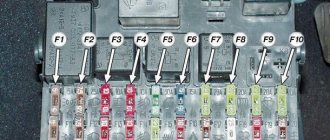
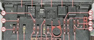
- Disassemble the mounting block and remove the panel from it.
- Next, you need to wash the bare panel with a soda solution and leave to dry for 1-2 days. This will help get rid of oxides and dirt - it will be easier to work.
- If the track is slightly damaged (burnout occurred at only one point), it is enough to use a soldering iron and solder the damaged area.
- If the damage is serious, the track may peel off. It is recommended to use copper jumpers. A piece of insulated wire is soldered into the line instead of the track, and everything will work.
In severe cases, when a large number of tracks are damaged or the board itself is burned out, it is recommended to replace the entire panel.
Door insulation
Good interior sealing cannot be achieved unless the doors are insulated. First of all, all seals should be replaced - on the doors, body pillars, and window frames. These seals are made of rubber and gradually “shrink,” causing heat to escape through the leaks and drafts to form in the cabin. It is not possible to restore the “original” seals; they only need to be changed.
The door itself is also treated with insulating materials and for this they will have to be disassembled. Next, vibration and noise insulators are applied to the internal surfaces, and a heat insulator is applied to the door card.
All these treatments will ensure one of the main conditions for creating comfortable conditions - the tightness of the interior. And modernizing the stove will increase its efficiency.
Processing the engine compartment
But one more problem remains - the long time it takes to warm up the interior. And to eliminate it, you need to insulate the engine. This will allow the engine to reach operating temperature faster and cool down more slowly.
But it is not possible to insulate the motor itself; there are a significant number of moving elements on it that cannot be covered. But insulation of the engine compartment is allowed.
First you need to insulate the hood of the VAZ-2107. To do this, you can purchase a special cover from the auto store that is attached to the cover from the inside of the hood.
But many car enthusiasts prefer to do this with improvised materials. But when deciding to treat the hood, you should choose the right insulating materials. They must be non-flammable and not absorb oil. Therefore, it is not recommended to use ordinary fabrics.
The engine compartment can be better insulated by gluing insulating materials onto the shield separating the engine from the passenger compartment. But this can only be done by removing the engine from the car.
In addition to the hood, the radiator also needs to be insulated. For this purpose, masks are used that are attached to the radiator grille.
Instead of a mask, you can use a regular cardboard sheet placed between the radiator and the grille. But it is worth considering that you cannot completely close the radiator; heat exchange must still occur. Therefore, a sheet of cardboard should not cover more than 2/3 of the radiator area.
There is no need to take this into account with a mask, since in addition to the grille, there are enough holes in the front end for the air flow to pass to the radiator.
When to replace
According to the manufacturer's instructions, replacement should be carried out after traveling 10 thousand km when driving long distances and every 6 thousand km if trips were carried out mainly over short distances.
Also, the moment of replacement can be determined by the oil pressure sensor. Long service life dilutes the oil, so a cold engine shows high pressure, but after warming up the indicator drops significantly. Such differences signal the need for maintenance.
Source