Checking the generator voltage regulator may be necessary when problems with the battery begin to occur. In particular, it began to undercharge or overcharge. When such a malfunction occurs, it’s time to check the generator voltage regulator relay.
The relay should turn off at 14.8 V
The task of this simple device is to regulate the voltage of the electric current that is supplied from the generator to the battery. When it fails, the battery is either not charged enough or, on the contrary, overcharged, which is also dangerous, since this significantly reduces the battery life.
Agree that the prospect of killing a battery because of one small part is not very good. This is why it is so important to monitor the operating condition of the voltage regulator (it can also be called a pill or a chocolate bar). But in order to properly check the voltage regulator, you need to know its type and several important features.
Why do you need a voltage regulator in a car?
This small, simple device performs an important function - voltage regulation. That is, if the voltage is greater than set, the regulator should reduce it, and if the voltage is less than set, the regulator should raise it.
What voltage does the generator relay regulate?
When the engine is running, the generator operates, which generates and transmits electric current to the battery.
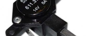
If the voltage regulator does not work correctly, the car battery quickly drains its life. The regulator is sometimes called a pill or a chocolate bar.
Types and types of relay regulators
Depending on the type of relay, the method for determining performance also depends. Regulators are classified into 2 types:
Combined relays - this means that the relay itself with the brush assembly is located in the generator housing.
Separate relays - this means that the relay is located outside the generator housing and is mounted on the car body. You've probably seen a small black device attached to the fender of the car, wires go to it from the generator, and from it to the battery.
A distinctive feature of regulators from other devices is that the relays consist of a non-separable housing. During assembly, the body is glued with sealant or special resin. There is no point in disassembling and repairing it, since such electrical appliances are inexpensive.
Signs of trouble
If the voltage is low, the battery will not be able to charge. Thus, the battery will quickly run out.
If, after the relay-regulator, the voltage goes to the battery at a high level (higher than set), the electrolyte will begin to boil and evaporate. At the same time, a white coating appears on the battery.
What signs of a breakdown of the car generator voltage regulator may be:
- After turning the ignition key, the warning lamp does not light up.
- After the engine starts, the battery indicator does not go out on the instrument panel.
- In the dark, you can observe how the light becomes brighter and dimmer.
- The car's internal combustion engine does not start the first time.
- If the engine speed exceeds 2000, then all the dashboard lights may turn off.
- Loss of engine power.
- Battery boiling.
Causes of relay malfunction
The reasons include the following observations:
- Short circuit (SC) on any line of automotive electrical wiring.
- Diodes are broken. The rectifier bridge has closed.
- The battery terminals are not connected correctly.
- Water got inside the relay.
- Mechanical damage to the housing.
- Brush wear.
- The relay resource has expired.
Why does it break?
Current relays are much more durable than their predecessors, but nothing is immune from failures. relay voltage regulator Factors such as:
- short circuit,
- penetration of moisture (can happen when washing the car),
- mechanical damage ,
- the quality of the product itself (purchasing a device from unknown manufacturers does not guarantee a long service life).
When the relay breaks down and recharging occurs, you need to diagnose the problem. There are two ways to check the generator voltage regulator - not removed from the car or removed . Let's consider both options.
Checking the voltage without removing the relay regulator
How to quickly and easily check the voltage regulator
Take a multimeter or voltmeter and measure the voltage at the battery terminals. The check is done in the following order:
- Put the device in voltage measurement mode at up to 20 V.
- Start the internal combustion engine.
- At idle speed, measure the voltage at the battery terminals. In XX mode, engine speed is from 1000 to 1500 rpm. If the generator and voltage regulator are working properly, then the voltmeter should show a voltage of 13.4 to 14 Volts.
- Raise engine speed to 2000-2500 rpm. Now the voltage value with the generator and relay working properly, the multimeter (voltmeter, tester) should show a voltage from 13.6 to 14.2 V.
- Next, step on the gas and increase the engine speed to 3500 rpm. The voltage of working devices should be no more than 14.5 Volts.
The minimum permissible voltage that a working generator and voltage regulator should produce is 12 Volts. And the maximum is 14.5 Volts. If the device shows a voltage value less than 12 V or more than 14.5 V, then the voltage regulator must be changed.
In new cars, mainly the relay is combined with a generator. This helps avoid pulling separate wires and saves space.
Recommendations for increasing the service life of the regulator
In order to increase the service life of the voltage regulator, it is necessary to adhere to several simple rules aimed at implementing preventive measures. Among them:
- do not allow excessive contamination of the generator, periodically inspect its condition, and, if necessary, dismantle and clean the unit;
- check the tension of the alternator belt, tighten it if necessary (either yourself or in a car service);
- monitor the condition of the generator windings, in particular, do not allow them to darken;
- check the contact on the control wire of the relay-regulator, both its quality and the presence of oxidation on it;
- Perform periodic voltage checks on the vehicle battery with the engine running.
Following these simple rules will allow you to increase the resource and service life of both the generator and the vehicle voltage regulator.
Results
Checking the voltage regulator relay is not a difficult task, and almost any car enthusiast with basic repair skills can handle it. The main thing is to have the appropriate tools for this - a multimeter, a power supply with a voltage regulator (although you can connect it to a battery with a charger), a 12 V lamp and pieces of wires for mounting the appropriate circuit.
If during the inspection you find out that the regulator is out of order, then it must be replaced (repair work is usually not carried out). The main thing is not to make a mistake when choosing it and purchase the part that is suitable specifically for your car.
Source
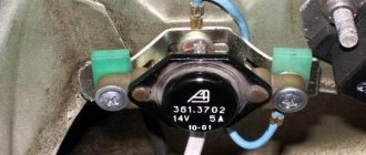
Checking the VAZ 2107 regulator
Until 1996, classic VAZ 2107 cars with a cipher generator 37.3701 were equipped with an old-style voltage regulator (17.3702). If such a relay is installed, then it should be checked as on the top ten (discussed above).
After 1996, they began to install a new generator of the G-222 brand (there is an integrated regulator RN Ya112V (B1).
Checking the regulator separately
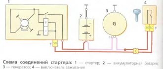
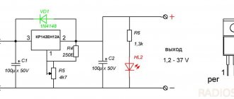
- 1 - battery;
- 2 - voltage regulator;
- 3 - control lamp.
To check, you need to assemble the circuit shown in the figure. At a normal operating voltage of 12 V, the light bulb should just glow. If the voltage reaches 14.5 Volts, then the light should go out, and when it drops, it should light up again.
Checking relay type 591.3702-01
Relay test diagram:
Such old relay models are sometimes installed on the classic VAZ 2101-VAZ 2107, on GAZ, Volga, Moskvich cars.
The relay is mounted on the body. It is checked according to the same scheme as the previous ones. But, you need to know the contact markings:
- “67” is the minus (-) contact.
- "15" is a plus.
The verification process is the same. At normal voltage, 12 Volts and up to 14 V, the light should light. If lower or higher, the light should go out.
PP-380
The RR-380 brand regulator was installed on VAZ 2101 and VAZ 2102 cars. Adjustable voltage at the temperature of the regulator and the environment (50±3) ° C, V:
- at the first stage no more than 0.7
- at the second stage 14.2 ± 0.3
- Resistance between plug “15” and ground, Ohm 17.7 ± 2
- Resistance between plug “15” and plug “67” with open contacts, Ohm 5.65 ± 0.3
- Air gap between armature and core, mm 1.4 ± 0.07
- Distance between contacts of the second stage, mm 0.45 ± 0.1.
Testing a three-level relay
As the name suggests, such relays have three voltage levels. This is a more advanced option. The voltage levels at which the battery will be disconnected from the voltage regulator can be set manually, for example: 13.7 V, 14.2 V, 14.7 V.
How to check the generator
To check functionality, you need to:
- Disconnect the wires going to terminals 67 and 15 of the regulator.
- Connect a light bulb to the wires. Bypassing the relay.
- Disconnect the positive terminal of the battery.
If the car does not stall, then the generator is working.
Checking the removed part
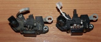
You can also test the element removed from the generator. To do this, you need to turn on a 1–3 W, 12 V lamp between the brushes of the brush holder. It is necessary to connect the power supplies to the D+ and ground terminals in turn. First we connect the source to 12 V, then to 15–16 V. If everything is normal, then when connecting the first option the lamp will light up, and with the second it will go out. If it lights up in both places, it means there is a breakdown in the regulator. A lamp that is not lit at all indicates a break or lack of contact between the components. To check for contact, connect the lamp not to the brushes, but to the D+ and DF terminals.
Video about the scheme of working with the regulator on a VAZ 2109 car
Video
Useful video for auto electricians.
How the generator and voltage relay work.
If you find problems with charging the battery from the generator, you need to check the regulator relay. This device is directly responsible for the normal operation and efficiency of battery charging. Moreover, the overall service life of the battery will depend on the health of the regulator relay.
The job of the regulator relay is to accurately maintain the voltage produced by the vehicle's alternator. In other words, the relay regulator functions as a voltage stabilizer. The device keeps the voltage within strictly specified limits, limiting the possible decrease or increase in the value. This regulation occurs constantly and does not depend in any way on the speed of the crankshaft and generator, as well as on the degree of load created by various consumers in the on-board network. It turns out that the relay regulator controls the “plus” of the battery, supplying or stopping the supply of electricity depending on the voltage reading at the battery terminal.
Read in this article
What else could it be?
Often, the culprit for charging problems may not be the regulator itself, but its terminals; over time, like many on a car, they oxidize - which prevents the generator from working normally and recharging our battery, so first, before changing this unit, try to clean it, remove oxides and other deposits. By the way, this also applies to the battery terminals; they need to be cleaned and protected at least once a season.
Therefore, first of all, if the multimeter gives you 11 or slightly below 12V at the terminals of the machine, try cleaning the terminals and contacts first, then measure again. It is quite possible that this is the reason.
This is where I end the article, I think it was useful, read our AUTOBLOG.
Similar news
- Is there an automatic clutch? Let's look at the technical details...
- DIY brake caliper repair. Plus detailed video
- Spark plug gap. What should it be and what does it affect?
Add a comment Cancel reply
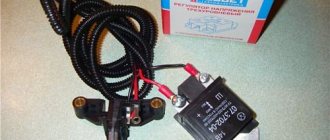
How to check the relay regulator yourself
To check the proper operation of the regulator relay, you can remove the device from the car. The second way would be diagnostics directly on the car. To perform the work you will need a test lamp and a multimeter tester.
It is also necessary to prepare a special power supply or charger, wires in advance, and also make sure that the battery is in working condition.
- To check the relay regulator, you need to set the voltmeter mode on the multimeter to be able to measure direct current in the range from 0 to 19 volts.
- Next, connect the multimeter probes to the “poles” of the battery with the engine turned off. Record the data that the voltmeter shows. The voltage should be between 12 and 12.5 volts. After this, the engine starts, and the voltmeter readings are recorded again. Normally, there should be an increase in values after starting the internal combustion engine to an average of 13-13.5 volts.
- Additionally, it is worth considering that as the engine speed increases, the voltage should also increase. In the middle range this figure is about 14 volts, at high speeds it reaches 14.5.
Testing an Individual Relay
Similarly, you can check a new type of regulator, that is, a separate one, here the verification process is much easier. For example, let’s take a model like Y112B; they were installed on many domestic cars before (VAZ).
This is a separate element, so we simply unscrew it from the body (sometimes from the generator cover) and attach it to our stand. Once again, I would like to remind you that it is advisable to have a 12V power supply, then the testing process will be much easier. If not, we use a charger (with adjustment modes) and connect it according to the lower diagram.
The check is the same, we increase the voltage to 14.5 V, the lamp should go out, if not, or turns off at a voltage much higher, then the relay has failed and needs to be replaced.
Tips and tricks
A common culprit for malfunctioning regulator relays may be oxidation of its terminals. This oxidation results in significant voltage loss. In this case, it is necessary to thoroughly clean the contacts and recheck. The voltage reading at the contacts should be similar to those given by the battery itself, that is, there should be no noticeable losses. Reduced voltage at the contacts indicates that they should be cleaned, and the regulator itself is often in working order. After cleaning, the terminals can be additionally treated with special chemicals that prevent further oxidation.
Finally, I would like to add that the cost of the regulator relay is not high. One of the surest ways would be to replace it with a new element if malfunctions are detected in its operation. Moreover, integrated relay regulators are a part in a monolithic housing that cannot be disassembled for repairs. Savings on this device are not justified, since rapid battery failure or a significant reduction in battery life will entail more serious costs when it is necessary to replace the battery.
Correctly charging a car battery with a charger. Before charging, check what current to charge the battery with. How to charge a battery without a charger.
The principle of operation and design of a car generator. The components of an alternator in a car: rotor, stator, windings, regulator.
How is the density of electrolyte in a battery measured, what does this indicator depend on. Affordable ways to increase the density in battery “banks” with your own hands.
For what reasons does the electrolyte in the battery become cloudy, gray or black? In what cases and in what ways can you restore battery functionality?
Why the starter may not work after turning the key in the ignition. The main causes of starter malfunctions: bendix, traction relay, brushes, winding.
Purpose, design features, installation location of the fuel pressure regulator of an injection engine. Signs of RTD malfunctions, checking the device.
A relay regulator is installed on cars to maintain stable voltage from the generator. This element protects the battery from overcharging, extending the battery life. It is the breakdown of the generator voltage regulator relay that is one of the most common malfunctions of the vehicle’s on-board network.
Problems with the battery: charging the VAZ 2106 and diagnosing faults
As a rule, before checking the regulator of a VAZ 2107, 2106 or any other car, it is necessary to review in general terms the design and operating principle of such a regulator.
Let's start with the fact that the design of the regulator may differ. Old VAZ 2106 models have outdated contact regulators. At the same time, newer versions already use an electronic regulator.
- So, the contact external regulator is still the basis. This is a semiconductor type device manufactured on a single board. The main element is the winding (brass wire is used), the winding consists of just over a thousand turns, and there is a copper core inside the winding. The winding has a constant resistance of 16 ohms.
The regulator also uses a group of tungsten contacts, an adjustment plate, and a magnetic shunt. A set of resistors is used in parallel, and their connection differs depending on what voltage is required. The resistors provide a maximum resistance of 75 ohms. All components are located in a textolite case, with contacts for connection brought out.
Let's move on. When the internal combustion engine starts, the crankshaft rotates, from which the attachments are also driven. The generator on many cars is no exception, that is, the rotor in the generator is also driven by the engine. So, when the engine rotates at a frequency of about 2 thousand rpm, the voltage at the generator outputs is no higher than 13 Volts.
In this case, the regulator does not turn on; the current goes directly to the excitation winding. However, when the engine rotation speed increases, as well as the generator rotor, the voltage regulator automatically turns on.
On a VAZ 2106, the relay regulator is connected to the generator brushes, as well as to the ignition switch. Also, the winding connected to the generator brushes actively reacts to the fact that the internal combustion engine speed increases and, as a result of such an increase, becomes magnetized.
Next, the core in the winding is pulled inward, which leads to the opening of the contacts on the internal resistors of one group and the closure of the contacts on the resistors of the other group. For example, when the speed is not high, only one resistor in the regulator remains closed, while when operating at high speeds, three resistors are closed, and the voltage on the excitation winding drops significantly.
Possible causes of failure of the regulator relay
Modern relay models have a relatively long service life. But some factors can lead to premature failure of the element, namely:
- Low quality of the part itself.
- The occurrence of a short circuit.
- Mechanical damage to the part.
The problem may also be caused by water ingress.
On some generator models, replacement of the electronic regulator relay will be necessary if the brushes are worn out. Under normal conditions, the life of the voltage regulator exceeds 60,000 km.
Causes and possible consequences of the malfunction
The generator may not work for the following reasons:
- malfunction of the voltage regulator (“pills”, “chocolates” in the slang of car enthusiasts);
- wear (destruction) of brushes;
- short circuit of the exciting winding (rotor);
- breakdown of diodes (located in the horseshoe);
- wear of bearings and bushings.
A faulty voltage regulator usually results in a lack of battery charge. In this case, the “battery” indicator light appears on the dashboard. The engine continues to run until the battery is discharged to approximately 8 - 9 volts.
During daylight hours, the battery charge may be enough for 30-50 kilometers, provided that the battery was well charged at the time the malfunction occurred.
If the output stages of the voltage regulator breakdown, a malfunction may occur due to an increase in the generator output voltage to 17 - 20 Volts. This recharges the battery. The consequence of overcharging is the process of boiling of the electrolyte. If signs of corrosion appear under the hood in the battery area, it is necessary to check the generator.
A breakdown of the diode bridge can occur when the battery is accidentally reversed (installing the terminals in the wrong polarity). Typically, diodes are punched in pairs in one arm. A faulty diode has a resistance close to zero. In this case, the stator winding of the generator operates in short circuit mode and becomes very hot.
Read also: Angle attachment for screwdriver
After a few minutes of engine operation, the windings overheat, and a smell of burnt electrical wiring appears under the hood of the car. To avoid fire, the engine must be turned off and the generator checked.
Wear of the brushes leads to gradual failure of the generator. First, while driving, the charge indicator light on the dashboard begins to blink, then it begins to glow constantly. In many generator models, the brushes are changed together with the voltage regulator.
A short circuit in the generator windings can lead to a significant change in output parameters and overheating of the device.
Main symptoms of a malfunction
There are two main “symptoms” of a relay failure. This is an undercharge or overcharge of the battery. Also, a malfunction of a part can be determined by the dim glow of the headlights or by a change in their brightness when the engine speed increases.
If undercharged, the car will start with great difficulty. However, the manifestation of this “symptom” may not be related to the generator. Therefore, first of all, you should make sure that the battery is in good condition.
If the battery is overcharged, there is no doubt that the problem lies in the damaged relay. There are other possible causes of overcharging, but they are extremely rare. Overcharging may cause the battery to boil over. This can be determined by the decrease in the amount of electrolyte in the jars and the appearance of a white coating on the battery.
If you suspect that the battery is overcharged or undercharged, you should diagnose the generator.
Precautionary measures
The operation of a generator set requires compliance with certain rules, mainly related to the presence of electronic elements in them.
- The generator set must not be operated with the battery disconnected.
Even a short-term disconnection of the battery while the generator is running can lead to failure of the voltage regulator elements. If the battery is completely discharged, it is impossible to start the car, even if you tow it: the battery does not provide excitation current, and the voltage in the on-board network remains close to zero. It helps to install a properly charged battery, which is then replaced with the old, discharged one while the engine is running. To avoid failure of the voltage regulator elements (and connected consumers) due to increased voltage, it is necessary to turn on powerful electrical consumers, such as heated rear windows or headlights, while the batteries are being replaced. In the future, after half an hour or an hour of engine operation at 1500-2000 rpm, the discharged battery (if it is in good condition) will be charged enough to start the engine. - It is not allowed to connect electrical sources of reverse polarity (plus to ground) to the on-board network, which can happen, for example, when starting the engine from an external battery.
- Any checks in the generator set circuit with the connection of high voltage sources (above 14 V) are not allowed.
- When carrying out electric welding work on a car, the ground terminal of the welding machine must be connected to the part being welded. The wires going to the generator and voltage regulator should be disconnected.
Generator Maintenance
Maintenance of the generator set is kept to a minimum and does not require any special knowledge or skills; this work can be performed by every car enthusiast. Start servicing the generator by cleaning the external surfaces. Check the fastening of the generator to the engine, the reliability of the connection of the wires to the generator and voltage regulator, as well as the tension of the fan drive belt. If the tension is weak, then the generator operates unstable; if it is strong, the belt and bearings wear out quickly. Also check the condition of the drive belt. There should be no cracks or delaminations on it. The condition of the bearings can be checked by rotating the generator rotor by hand with the drive belt removed. When the bearings are in normal condition, the shaft rotation should occur smoothly, without jamming, strong play, noise or clicks. In principle, this work can be limited to until any malfunctions appear.
Control check
Before leaving, it is recommended to check the functionality of the generator set using the warning lamp installed on the instrument panel. After turning on the ignition and before starting the engine, the warning lamp lights up, which allows you to check its functionality. During normal operation of the generator set, the warning lamp goes out after the engine starts. For a normally operating generator set, at average engine speeds, the voltage should be in the range of 13.5...14.2 V. The magnitude of this voltage is measured with a voltmeter at the battery terminals.
Pre-repair diagnostics
A flashing battery charging indicator lamp does not always indicate a malfunction inside the generator. Often the malfunction is trivial and lies on the surface. Therefore, you should not immediately go into the generator and change the relay-regulator headlong, maybe it will help. Look at the preliminary diagnostic diagram. To carry it out, you may need a voltmeter with a scale of at least 15 V. Anyone can do these checks and thereby protect themselves from unnecessary, incorrect actions and loss of precious time.
If preliminary diagnostics have shown that the excitation winding circuit is working properly, and the fault is in the generator, then after removing it, it is advisable to check all the circuits, including the relay regulator, according to the diagrams described in the section
Removing and installing the generator
- Disconnect the negative wire from the battery terminal (key 10).
- Remove the plastic strap clamps from the air intake pipe and the starter and alternator wiring harness.
- Disconnect the generator field winding connector.
- Unscrew the nut from the 30th terminal of the generator (10 wrench).
- Unscrew the nut securing the generator to the tension bar (17 wrench).
- Using a mounting paddle, move the generator to the engine and remove the drive belt.
- Unscrew the three crankcase protection bolts (head 13) and remove it.
- Remove the right engine splash guard by unscrewing the five self-tapping screws with a 8mm socket head.
- Unscrew the nut 19 from the lower bolt securing the generator to the bracket.
- Remove the generator along with the air intake pipe. To do this, you need to tilt it slightly so that it goes down between the side member and the lower bracket for mounting the generator.
- Install the generator in reverse order.
Disassembling and replacing the voltage regulator
Begin your preparation by cleaning the outside surfaces of the generator.
- Remove the back cover along with the air intake pipe.
- Disconnect the wire from the relay regulator, unscrew the two M4 screws and remove the relay regulator. To remove the old-style relay-regulator, unscrew the wire secured under the extension terminal “30” of the generator. Insert the blade of a screwdriver between the relay-regulator housing and the brush holder. Using a screwdriver as a lever, pull out the relay regulator and pull out the brushes.
- Blow dust and dirt out of the internal cavity of the generator with compressed air using a compressor or pump.
- If the rotor contact rings are severely burned or worn, clean them with fine sandpaper.
- Install the new relay-regulator in the reverse order of removal.
If, after checking, the old relay-regulator turns out to be in working order (the test method is described in the next section), then:
- Clean the contact connections of the generator and relay-regulator from dirt and oil with a rag soaked in gasoline or solvent. Oil and dirt increase resistance at the contact points, which reduces the current delivered by the generator and increases wear on the brushes.
- check the minimum permissible protrusion of the brushes from the brush holder - 5 mm. If the brushes are stuck in the brush holder, replace the relay-regulator assembly. (For old-style relay regulators, it is enough to replace only the brush assembly.)
- put it in place.
Troubleshooting generator set components and parts
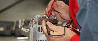
To find faults in the electrical circuits of the generator set, it is enough to have an ohmmeter. A more accurate check of winding units requires the use of special devices, such as PDO-1, which is used to search for faults in the windings by comparing their parameters. To check the relay regulator, you will need DC voltage sources of 12...14 V and 16...22 V. It is more convenient to carry out all tests on a generator removed from the car.
Checking the voltage regulator
Voltage regulators are not repaired, but replaced with new ones. However, before replacing it, it is necessary to establish exactly what it is that has failed.
Check on the car
To check, you must have a DC voltmeter with a scale of up to 15...30 volts. With the engine running at medium speed and the headlights on, measure the voltage at the battery terminals. It should be within the range of 13.5...14.2 V. If there is a systematic undercharging or overcharging of the battery and the regulated voltage does not fall within the specified limits, it is possible that the voltage regulator is faulty and needs to be replaced. In order to find out whether the regulator is working or not, we will check it according to the figure shown below.
Checking the removed regulator
The regulator removed from the generator is checked according to the following diagrams (old model on the left, new model on the right):
It is better to check the relay-regulator assembled with the brush holder, since in this case you can immediately detect breaks in the brush leads and poor contact between the terminals of the voltage regulator and the brush holder. Between the brushes, turn on a 1...3 W, 12 V lamp. To terminals “B”, “C” and to the regulator ground, connect a power source first with a voltage of 12...14 V, and then with a voltage of 16...22 V. If the regulator is working properly, then in the first In the second case, the lamp should be on, and in the second case, it should go out. If the lamp lights up in both cases, then there is a breakdown in the regulator, and if it doesn’t light up in both cases, then there is a break in the regulator or there is no contact between the brushes and the terminals of the voltage regulator.
Checking the rotor winding (excitation)
To check the winding, turn on the ohmmeter to measure resistance and bring its leads to the rotor rings. A working rotor should have a winding resistance in the range of 1.8...5 Ohms. If the ohmmeter shows an infinitely high resistance, this means that the field winding circuit is open. The rupture most often occurs at the place where the winding leads are soldered to the rings. You should carefully check the quality of this soldering. The check can be carried out with a needle, moving the winding leads at the place where they are soldered. The combustion of the winding is indicated by darkening and shedding of its insulation, which can be detected visually. The combustion of the windings leads to a break or an interturn short circuit in the winding with a decrease in its total resistance. A partial interturn short circuit, in which the winding resistance changes little, can be detected with the PDO-1 device by comparing this winding with a known good one. After checking the winding resistance, you should check that it does not have a short to ground. To do this, one ohmmeter lead is brought to any rotor ring, and the other to its beak. For a working winding, the ohmmeter will show an infinitely high resistance. A faulty rotor must be replaced.
Checking the stator winding
The stator is checked separately, after disassembling the generator. The terminals of its winding must be disconnected from the rectifier valves.
First of all, check with an ohmmeter whether there are any breaks in the stator winding (a). Then, by connecting the ends of the ohmmeter to one of the winding terminals and the non-insulated section of the stator iron, check whether its turns are shorted to ground (b). The ohmmeter should show an open circuit in a working winding. Checking the turn-to-turn short circuit in the stator windings can be carried out with sufficient accuracy using the PDO-1 device. The break can also be checked with an ohmmeter by connecting it to the zero point and alternately to the output of each phase. An external inspection should make sure that there is no cracking of the insulation and no burning of the winding, which occurs when there is a short circuit in the valves of the rectifier unit. Replace the stator with such damaged winding.
Checking the valves (diodes) of the rectifier unit
The diodes of the rectifier unit are checked after disconnecting it from the stator winding with an ohmmeter. A working valve allows current to flow in only one direction. Faulty - may either not pass current at all (open circuit), or pass current in both directions (short circuit). If one of the rectifier valves is damaged, the entire rectifier unit must be replaced. A short circuit in the valves of the rectifier unit can be checked without disassembling the generator, but only by removing the protective casing. Also, terminal “B” of the regulator is disconnected from terminal “30” of the generator and the wire from terminal “B” of the voltage regulator. You can check with an ohmmeter or using a lamp (1...5 W, 12 V) and a battery. In order to simplify the fastening of rectifier parts, three valves (with a red mark) create a “plus” of rectified voltage on the housing. These valves are “positive” and they are pressed into one plate of the rectifier block, connected to terminal “30” of the generator. The other three valves (“negative” with a black mark) have a “minus” rectified voltage on the body. They are pressed into another plate of the rectifier unit, connected to ground. First, check if there is a short circuit in the “positive” and “negative” valves at the same time. To do this, connect the “plus” of the battery through the lamp to terminal “30” of the generator, and the “minus” to the generator body:
If the lamp is on, then the “negative” and “positive” valves have a short circuit. A short circuit of the “negative” valves can be checked by connecting the “plus” of the battery through a lamp to one of the mounting bolts of the rectifier unit, and the “minus” to the generator housing:
The lamp burning means a short circuit in one or more “negative” valves. It should be remembered that in this case, the burning of the lamp may also be a consequence of the short circuit of the turns of the stator winding to the generator housing. However, such a malfunction is less common than valve short circuits. To check for a short circuit in the “positive” valves, connect the “plus” valves of the battery through a lamp to terminal 30 of the generator, and the “minus” valve to one of the bolts securing the rectifier unit:
The lamp will indicate a short circuit in one or more “positive” valves. A break in the valves without disassembling the generator can be detected either with an oscilloscope or when checking the generator on a bench by a significant decrease (20-30%) in the amount of current supplied compared to the rated one. If the windings, additional diodes and the generator voltage regulator are working properly, and there is no short circuit in the valves, then the reason for the decrease in the output current is a break in the valves.
Checking additional diodes
The short circuit of additional diodes can be checked using the following diagram:
Connect the “plus” of the battery through a lamp (1...3 W, 12 V) to terminal “61” of the generator, and the “minus” to one of the mounting bolts of the rectifier unit. If the lamp lights up, then there is a short circuit in one of the additional diodes. You can find a damaged diode only by removing the rectifier unit and checking each diode individually. A break in additional diodes can be detected with an oscilloscope by the distortion of the voltage curve on plug “61”, as well as by low voltage (below 14 V) on plug “61” at an average rotation speed of the generator rotor.
Capacitor check
The capacitor serves to protect the vehicle's electronic equipment from voltage surges in the ignition system, as well as to reduce interference with radio reception. Damage to the capacitor or loosening of its mounting on the generator (deterioration of contact with ground) is detected by an increase in interference to radio reception when the engine is running. Approximately the serviceability of the capacitor can be checked with a megger or tester (on a scale of 1...10 MOhm). If there is no break in the capacitor, then at the moment the probes of the device are connected to the terminals of the capacitor, the arrow should deviate in the direction of decreasing resistance, and then gradually return back. The capacitance of the capacitor, measured with a special device, should be 2.2 μF + 20%.
Checking and replacing bearings
Start checking the bearings with an external inspection, identifying cracks in the races, enveloping or chipping of metal, the presence of corrosion, etc. Check for ease of rotation and the absence of strong play and noise. If the bearing seats are heavily worn or damaged, it must be replaced. Procedure for replacing bearings (generator removed from vehicle).
- Remove the rear cover along with the air intake pipe.
- Remove the voltage regulator.
- Unscrew the generator pulley and remove the key.
- Unscrew the 4 nuts of the coupling bolts and remove the front cover of the generator along with the rotor and bearings.
- Remove the defective bearing from the drive side cover. Unscrew the nuts of the screws tightening the bearing mounting washers, remove the washers with screws and press out the bearing using a hand press. If the screw nuts do not come off (the ends of the screws are open), cut off the ends of the screws.
- Press in the new bearing. To do this, place the new bearing on the seat, and the old one on top of it. Lightly tap the old bearing with a hammer to force the new bearing into its seat. If the bearing has too much interference, spray the outer ring with WD-40.
- Using a puller, press the second bearing from the back of the rotor.
- Press in a new bearing (see point 6).
- Reassemble in reverse order.
Checking the covers
An external inspection determines the absence of cracks passing through the bearing seat, broken legs of the generator mounting, and severe damage to the seats. If such damage is present, the cover must be replaced. If severe wear of the bearing seats is detected, replace the caps.
Checking with a multimeter without dismantling
You can check the condition of the relay using a multimeter. In this case, the generator is not dismantled. Before starting diagnostics, it is enough to clean the battery terminals (their oxidation can affect the operation of the car and the readings of the measuring device).
The diagnostic procedure is as follows:
- First you need to start the engine and let it warm up for a few minutes.
- Next, you need to connect the multimeter probes to the battery terminals. The device displays a value of 20V.
- After this, the voltage is measured. It should be within 13.2-14V. Such readings are considered normal for most cars.
- Now you need to increase the engine speed (up to 2-2.5 thousand). The voltage should increase by about 0.2V.
- If it exceeds 3,500 rpm, the multimeter should show 14-14.5V, but no more.
Serious deviations in the readings of the device indicate the presence of breakdowns of the relay regulator.
Checking generator components
The test begins with monitoring the functionality of the voltage regulator. To do this, the regulator is removed from the generator and a simple electrical circuit is created.
Any car interior light bulb can be used as an incandescent lamp. If voltage regulator 3 is working properly, lamp 6 should not glow at full power. When connected in parallel with the lamp (brushes) of a multimeter, its readings should be from 5.0 to 10.0 Volts. If the multimeter readings fall outside these limits, the regulator must be changed. The design of some generator models allows for the possibility of replacing the regulator without dismantling the device.
Next, check the exciting winding of the generator for breakdown. To do this, set the multimeter to resistance measurement mode at a limit of 200 kiloOhms. The probes are connected: black - to the commutator lamella, red - to the metal part of the armature. The resistance should be more than 100 kiloohms or higher than the upper limit of measurement, as shown in the photo.
The resistance between the lamellas (rotor windings) is usually 0.5 - 2 Ohms.
Checking the stator begins with checking the windings for breakdown. To do this, the red probe of the multimeter is connected to the metal part of the stator, the black probe is connected in series to the windings.
The resistance must be above the upper measurement limit. Then the resistance between the winding contacts is measured. They should differ by no more than 5%. The measurement limit of the multimeter is set to 200 ohms.
If the winding has an electrical breakdown, a short circuit of the turns or a break, it must be replaced. There are workshops that rewind stators and rotors.
To check the health of the diode bridge, the multimeter measurement mode is switched to the “diode” test. Then the diodes (their number on a horseshoe is usually 9) are sequentially “ringed” in forward and reverse connection. In the forward direction (black probe to the cathode) the resistance is 550 - 700 Ohms, when switched in reverse it is greater than the maximum measurement limit.
When the diodes breakdown, the resistance in all directions will be practically zero. This diode should be changed. The difficulty of replacing a diode lies in the fact that the diodes in generators are not soldered, but spot welded to ensure reliable contact at different temperature conditions.
A car generator is an important part of a car's electrical equipment. At the first sign of inoperability, it is necessary to check it using a multimeter.
Inside each car there is a miniature power station - a generator, which is responsible for generating electricity. If something breaks in it, the battery will start to work incorrectly. The result is a suddenly stalled engine. For some reason this always happens at the most inopportune moment. To avoid being left without a car somewhere in the wilderness, periodically check the generator voltage regulator.
Read also: Connecting Internet wires by color
How to test a relay with a lamp
On many modern cars, the relay is combined with brushes. In this case, you can check the regulator using an incandescent lamp. The procedure will be as follows:
- To get to the part, you need to unscrew the mounting bolts and remove the terminals. The relay is located at the rear of the generator.
- To check, you need to prepare a 12V light bulb with a socket, wires, a voltmeter, and a power supply (no more than 20V).
- Next you will need to assemble the following circuit.
- After connecting the light bulb, it should light up. At the same time, the voltage gradually increases. When it reaches 14.5V, the light should go out. If this happens later, it means the relay regulator is faulty.
When the voltage decreases, the lamp should light up again.
This test method can also be used for some models of regulators that are not combined with brushes.
Repair or replacement?
It is more advisable to buy a new regulator. If it fails, the component parts of the element are seriously damaged. Of course, you can try to restore functionality, but in this case you risk being left with a broken generator somewhere outside the city.
By the way! On VAZ cars, you can try the following method as a temporary measure:
- remove the headlight bulb from the right headlight;
- We install one of its spirals on the terminals removed from the failed regulator.
If everything is done correctly, the emergency lamp will go out, and the one you need will light up and you will be able to get to the service center. However, remember that “folk” methods are used at your own peril and risk.