And so it happened, 2 days ago I purchased a 3-level regulator, because... the generator under load did not produce the desired result. With a heavy load, the headlights + stove + heated glass + wipers + cooling fan produced 10.9-11 V. Without a load, 13.6 V was normal, after consulting with experts, everything pointed to the voltage regulator, because if the diode bridge was faulty, charging would not hold and at idle. The difference between a regular regulator and a 3-level regulator is not big in price, so I chose it.
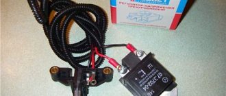
the box is simple.
the wire is quite long.
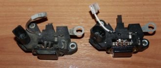
The brushes themselves are without tablets.
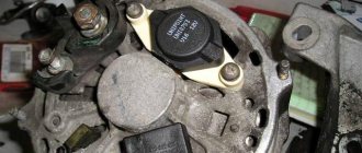
actually the board itself is under the cover.
Last night I rushed to a friend's garage and started installing it. I will say one thing, the installation turned out to be easier than I thought. I removed the first protection and voila, access to the generator is free.
standard regulator.
As I read in various topics, all the regulators are mounted on bolts with a screwdriver, but in my case it turned out to be on turnkey bolts, as it later turned out to be 6 (too non-standard). I removed the terminal from the regulator and unscrewed it, and this is the result.
one is shorter than the other.
such a pill.
One brush turned out to be shorter than the other, and compared to the new brushes, these looked much shorter. I don’t know for sure, is this too critical wear?
comparison of brushes.
Next I installed new brushes on the generator. It’s easy to install; you can crawl on top of the generator with your left hand and hold the brushes from the top while you screw in the bolts.
New brushes.
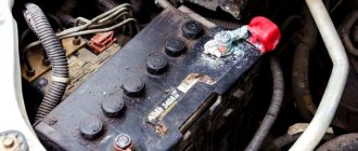
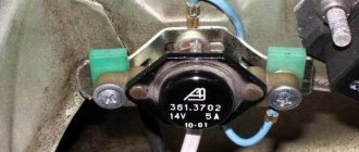
The regulator body itself was screwed onto the body ground to the gas valve.
sat down like clockwork.
I put the toggle switch in the middle position, and the gene outputs 13.7-14 V. During the trip, the voltage remained steady, sometimes dropping to 12.8. In general, I'm happy, compared to what it was like. Next, we’ll travel and see how the regulator behaves.
Voltage regulator VAZ 2107 - purpose and first signs of malfunction
The voltage regulator is designed to automatically maintain the current strength so that the voltage generated by the generator is within specified limits, regardless of the rotation speed of the generator shaft (from the engine speed) and the current consumption of the car's electrical network. In VAZ 2107 cars, as a rule, an electronic voltage regulator is installed on the generator.
It is extremely rare that some models may come across an old-style device - a relay regulator. They were installed on generators 37.3701, produced before 1996, and on G-222. First, the device is tested on a running car. To do this, you need a voltmeter with the ability to measure DC voltage. The device must be equipped with a scale for values up to 15–30 V and have an accuracy class of at least 1.0. After starting the VAZ 2107 engine, it is allowed to run with the headlights on for 15 minutes at medium speed.
Then the voltage at the generator output is measured. To do this, the positive probe of the device touches terminal “30” on the generator, and the negative probe touches the ground (generator or car - it doesn’t matter, it’s the same thing). The voltmeter should show a voltage between 13.6–14.6 V. If the measurement result turns out to be higher or lower than specified, and the vehicle is experiencing systematic overcharging or undercharging of the battery, then most likely the regulator is faulty and needs to be replaced.
Lada 2106 classicツ › Logbook › How to check the generator with a multimeter
The generator is one of the most important devices in a car. Without it, the normal functioning of all blocks, components and devices that require electrical energy becomes impossible. After starting the engine, the autogenerator is turned on to power the on-board network, as well as to charge the battery
It is important to monitor and periodically check the tension of the alternator belt. Not only the service life of the belt itself depends on this, but also the normal charging of the battery
If adjusted incorrectly, the belt may slip, resulting in insufficient tension. In such a situation, the battery will not receive the necessary charge and may discharge over time (how to properly charge the battery).
If any problems arise with the power supply, the first question that faces the driver is how to check the operation of the generator. Of course, the ideal option is to carry out diagnostics at a service station. However, for example, if after a long stay in the garage the car does not start, you should not immediately look for a towing cable. Below we will describe in detail how to test a generator with a regular tester (or, in other words, a multimeter).
To check, we need a multimeter and, preferably, an assistant (a neighbor, a friend, or even, in extreme cases, a wife). It is worth mentioning that the tester, multimeter and avometer are actually the same device; the differences lie only in additional functions.
Sequence of actions 1. First you need to check the generator relay. Overvoltage in the vehicle's on-board network can damage various devices. To maintain the correct potential difference, a relay regulator is used. We will describe in detail how to check the generator voltage regulator. Switch the multimeter to voltage measurement mode. We start the car. We measure the voltage at the battery terminals or generator outputs. The correct value should be in the range of 14-14.2 V. Press the accelerator (here you will need the help of an assistant). The voltage value should not change by more than 0.5V. If the values of the measured parameters differ from those given, this indicates improper operation of the relay regulator. 2. Check the diode bridge, consisting of six diodes. Of these, three can be called “positive”, and three can be called “negative”. Half of the diodes have mass at the anode, and the rest at the cathode. To check, switch the multimeter to “sound” mode. If you close the contacts of the probes, a squeak will be heard. We check each diode in both directions. The squeak should only be heard in one. If the diode rings in both directions, it means it is broken and needs to be replaced. In this case, it is advisable to replace the entire bridge at once. 3. Check the generator stator. This block is made in the form of a hollow metal cylinder. The generator winding is laid inside. To check, you must first disconnect the stator leads from the diode bridge. We inspect the condition of the winding. There should be no burning or mechanical damage. We switch the tester to resistance measurement mode. We check the winding for breakdown. For this purpose, we measure the resistance between the stator housing and any of the winding terminals. The value should be as large as possible, ideally tending to infinity. If the tester shows less than 50 KOhm, it means that the autogenerator will soon fail. 4. Check the generator rotor. This unit is made in the form of a metal rod on which the winding is wound. There are rings at one end of the rod. The generator brushes slide along them. We remove the rotor and inspect the condition of the windings and bearings. We check the integrity of the winding with a multimeter. We measure the resistance between the slip rings. Its value should be on the order of several ohms. In case of a short circuit (resistance near zero) or an open circuit, the rotor must be replaced.
This instruction will help you successfully identify a fault generator in the field. The above algorithm can be successfully applied both on most modern cars and on domestic VAZ 2106, 2107, 2114, etc. The main condition is that the on-board voltage is 12V.
Checking the removed voltage regulator
To clarify the condition of the regulator, it must be removed. It is better to test the device complete with brushes and brush holder. This will allow you to immediately detect:
- poor contact between the terminals of the brush holder and the voltage regulator;
- breaks in the output conductors of the brushes.
Electronic devices are produced already assembled with a brush holder and one-piece brushes. The relay regulator will need to be connected to the removed brushes.
A voltmeter or a 12 V lamp with a power of 1–3 W is connected to the brushes of the device removed from the generator 37.3701. For the regulator from the G-222 generator, the connection is made to terminals “B” and “W”. The “plus” of the power supply is connected to the terminals “B”, “C” (when they exist), and the “minus” to ground. First, a voltage of 12–14 V is applied, and after that – 16–22 V. A sign of the device’s serviceability will be the lamp lighting up (deviation of the voltmeter needle) in the first case and going out (zeroing the voltmeter) in the second.
When the lamp lights up in both cases, this means that there is a breakdown in the device. If in both cases the lamp does not light, then there is no contact between the regulator terminals and the brushes, or there is a break in the device. Another cause of improper voltage regulation can be worn or stuck brushes. They must protrude from the housing of the electronic device or the brush assembly of relay regulators by no less than 5 mm.
Diagnostics
To check the installed relay, simply measure the voltage at the battery terminals, and it will become clear what condition it is in. To check what has been removed and is suspicious, the verification method is slightly different, but in any case it will help to identify:
- Absence or poor contact in the brush holder terminals.
- Broken brush conductors.
- The relay itself is faulty.
A multimeter or a 12-volt test lamp, the power of which does not exceed 2 W, is simply connected to the regulator It is enough to apply 10-12 V, the lamp should light up or the multimeter should show the corresponding value. If you do not want to seek help from a qualified specialist, it is better to replace the timing belt on a VAZ 2112 with 16 valves. After this, a voltage greater than the nominal voltage is supplied - 16-20 volts. Replacing the regulator installed on the engine, removing and replacing the VAZ-2107 generator. Voltage regulator relay VAZ 2107 | Lada master. In this case, the relay should operate, but the lamp should not light. If the lamp continues to light when the voltage increases, then the regulator is broken and does not perform its functions. In this case , it must be replaced. Also, when replacing, you should pay attention to the condition of the brushes. They should protrude beyond the brush holder by no more than 5 mm.
This way you can test your regulator and save the battery from premature wear. Replacement of side glass for VAZ 2113, VAZ 2114, VAZ 2115. Monitor the voltage in the network, and have a good trip!
Replacing the voltage regulator VAZ 2107
If the regulator is faulty, the brushes are worn out or stick, then the device must be replaced. It cannot be repaired. For a relay-regulator in case of brush failure, it is sufficient to replace only one brush assembly. Usually they change it to a new electronic one, but you can install a three-level one, like 67.3702-02. They provide better voltage stabilization than standard regulators, taking into account the ambient temperature and vehicle operating conditions.
They are called three-level because they contain 3 voltage regulation modes. Their selection is carried out manually with a switch on the regulator, which is installed separately from the generator itself in a convenient protected place. The device is connected to the generator by wires through a brush assembly, which is supplied complete with the regulator.
Home → Device → Electrical system → Generator →
On VAZ 2107 cars, in fact, like on other models of the domestic automobile industry, there is one serious problem, which is associated with the rapid discharge of the battery. As a result, problems arise with starting the engine, and the headlights begin to shine dimly. You have to purchase a new battery almost once every 2-3 years, although during normal operation of the generator its service life is at least 5 years. To solve the current problem of undercharging, you can install a three-level voltage regulator for the VAZ 2107 car. In the design of the car, a standard regulator is installed from the factory, which has a simple design, which makes it ineffective.
Advantages of installing a three-level regulator
The three-level voltage regulator on the VAZ 2107 is capable of maintaining a constant voltage supplied by the generator to the vehicle network. With this product it is possible to save and increase the battery life. In addition to regulating voltage, three-position regulators are capable of maintaining current within a certain range.
Some of the main advantages of the device in question include:
- The main board of the device is located not in the generator itself, but away from it, which contributes to less heating of the product, as well as extending its service life.
- Possibility to regulate the voltage level manually thanks to a special switch. The device operates from a switch.
- The charge level is significantly higher, in contrast to standard products.
Problems with starting the engine, especially on frosty days when it is very difficult for the starter to start the engine, can be avoided by replacing the standard device with a three-position one. Large loads on the electrical circuit in a car, such as headlights, heater, heated glass, can contribute to battery discharge, even if the engine is running and the standard product is in good working order.
Types of regulator relays are simple, three-level and with temperature compensation. In the brush section of a standard seven generator, in most cases, a temperature-compensated option is installed. But, as practice shows, in terms of thermal regulation, these regulators are mostly ineffective. Recently, among drivers of the VAZ 2107 and other Lada models, the three-level type is gaining more and more popularity. Car owners who have installed such a regulator overwhelmingly recognize it as more effective than the standard one.
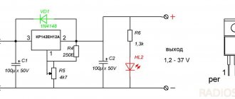
Characteristics of the Energomash device for VAZ 2107
The Energomash voltage regulator for the VAZ 2107 is equipped with three “25C” type diodes and a mode switch. With their help, a three-stage voltage change is carried out. A three-level balancer is also called a current injector, since the device is capable of maintaining it at a level of up to 6A. The main functionality of the three-level voltage regulator for the VAZ 2107 model "Energomash" is based on changing the current from the generator, thereby increasing the voltage of the on-board circuit to 13.6-14.7 V.
Malfunctions: Tired of installing a 3-level voltage regulator
Hello! After a small problem with the generator https://avtomarket.ru/journal/VAZ/2107/35838/ and replacing the burnt-out voltage regulator with a new one, I seemed to be happy, but after a couple of days it failed again. The voltage began to jump to 16.8-17 Volts, as measured by a multimeter, and a lamp for a problem with the engine lit up on the panel, which threatened to cause the entire electrical system to fail.
I removed the generator again, but now I took it to a mechanic I know to check, he confirmed my guesses that the regulator had burned out again and needed to be changed. This company may just have been defective.
Having thought about disassembling half the machine again next time, I decided to install an external regulator or, as a last resort, remove a standard tablet. But I remembered, having scoured the Internet, people gave advice to buy a three-level regulator from Energomash, so I went to the store and bought it. It is packed in a box, by the way, each generator has its own and has a different brush assembly, as I understand it.
It comes with a 1 year warranty. It differs from the standard “pill” in that the brush assembly is sealed off from the relay, and it is located in a small black box with a switch, and they are connected through wires.
There are 3 voltages on the regulator: low 13.6 V, nominal 14.2 V, and high 14.7 V. Depending on the ambient temperature, the state of the battery and consumers, it is switched manually via a toggle switch.
Without thinking twice, I installed the brush assembly in place; in the rear plastic cover of the generator it is necessary to cut off one edge to bring the wires out.
The regulator itself was screwed to a bolt on the wing to ground.
So, a confusion arises. When I start the car, I check the voltage on the battery - in all three modes at idle with the consumers turned off, it shows the declared values with slight deviations.
But as soon as you turn on all the consumers: heated rear window, low and high beams, fog lights and the stove, the voltage immediately drops and remains around 12 V and even lower, regardless of the mode in which the regulator operates.
I didn’t notice this with the standard regulator; before it burned out, it always held 14 V. I tightened the belt a little, checked the ground, measured the voltage on the go, everything worked out the same way, when a large number of consumers were turned on, the voltage tended to 12 Volts.
Only when reaching 2-3 thousand revolutions in 4th gear was the charging current nominal 14 V.
Is tension supposed to flow like that? What could be the cause of the malfunction, or is this how this regulator works? By the way, the battery has not yet been discharged after several days of such driving.
I think I'll check the battery just in case and throw some extra ground on the engine.
Good luck on the roads!
Such an inconspicuous, inexpensive and reliable element of a car's electrical network as the VAZ 2107 voltage regulator relay is rarely remembered. Usually, attention is paid to it only after the battery stops charging and problems with starting the engine begin. To prevent this, it is necessary to monitor the operation of the relay when the voltage of the on-board network is unstable and replace it if a malfunction is detected.
Content
Logbook VAZ 21074 (2006)
Last time I already described the situation. Briefly: the battery charge indicator lamp went out, the voltmeter needle did not show charging from the generator.
I disassembled the panel and checked the light bulb - it turned out to be intact, the next day I continued to find out the reason and, having scoured the Internet, got to work. I armed myself with an indicator screwdriver with a wire and a multimeter. Since the reason for the lack of charge is the extinguished control lamp, the first thing I decided to do was check the functionality of the “excitation circuit” of the generator. First, I visually inspected the battery terminals and the integrity of the wires going from it to the generator, to the mounting block and to ground.
Everything seems to be intact. Now, to determine whether the excitation current passes through the panel to the generator, turn on the ignition, take an indicator screwdriver (light bulb) or a short length of wire, connecting one end to the removed chip from the “61” input of the generator, and the other end to “ground” or negative battery terminal.
When a normal wire is connected to ground, the lamp in the instrument panel should light up, and when checking with an indicator screwdriver, either it itself or the lamp in the panel, depending on which has the lower resistance. In any case, we see that the circuit is not broken and the excitation current comes to terminal “61” of the generator. Thus, we conclude that the light bulb and the entire “excitation circuit” of the generator are operational, and the problem is in the generator.
Without removing the generator, I find out the serviceability of the voltage regulator assembled with the brush assembly. To do this, I take an indicator screwdriver and connect one end to terminal “61” of the generator, and the other to the positive terminal of the battery.
Our light bulb did not light up, which means there is a break inside the regulator and needs to be replaced. Therefore, I will remove the generator from the car, although this is not necessary - the regulator can be changed anyway, although it is quite difficult in -20 frosts. Using a 10mm wrench, unscrew the screws from the splash guard under the generator and bend it to the side.
Then we take the key 13 and unscrew the lower bolt securing the generator, and also remove the terminals from output “30”.
Unscrew the belt tension adjustment bolt from above and remove the belt from the generator pulley. We remove the generator from its seat through the lower opening. I bring the generator into a warm place and arm myself with a multimeter. Once again I am convinced that the voltage regulator is faulty by testing it with a multimeter.
As you would expect, the chain does not ring. I also check the diode bridge and windings for breaks and short circuits.
Everything is fine.
Thus, only the voltage regulator turned out to be faulty. We replace it with a new one bought in a store.
Reinstall the generator in reverse order, tighten the belt, and connect the charged battery. First, let's measure the voltage at the battery terminals with the car not running.
Turn on the ignition.
The battery lamp lights up, the voltmeter shows the battery charge level, current flows to the excitation winding. Now we start the car and observe the readings at the battery terminals.
As we can see, the generator works properly and creates a rated charging current of 14 V.
The lamp in the panel has gone out, the voltmeter needle is in battery charging mode. The problem has been successfully resolved. Step-by-step analysis:
Functions and location of the VAZ 2107 charging relay
In early models, an external voltage regulator VAZ 2107 was used, which was installed on the left arch in the engine compartment. In newer models, the relay began to be installed together with the generator brush mechanism. Regardless of the location and design (relays are produced on printed circuit boards or in the form of a single semiconductor module), the functions of the devices are the same - adjusting the voltage at the output of the car generator.
To maintain the correct battery charging mode and the normal functioning of the vehicle’s on-board network devices, the voltage at the generator output should be in the range of 13.6-14.6 volts (preferably closer to 14). The regulator relay changes the voltage in the generator excitation circuit depending on the output voltage so that at any load and speed it produces the optimal voltage. If the VAZ 2107 charging relay malfunctions, the mains voltage may be lower or higher than normal. In the first case, the battery will discharge, in the second, it will boil and may fail.
Checking the VAZ 2107 voltage regulator relay
If you suspect a malfunction, you should check the voltage directly at the battery terminals. If the voltage is below 13 or greatly exceeds 14 volts, there may be several reasons:
- voltage regulator relay malfunction;
- generator breakdown;
- poor contact in the electrical connections between the battery, alternator and relay.
The serviceability of the VAZ 2107 charging relay can be checked by disconnecting it from the vehicle’s on-board network. This is easy to do with the external one - just remove a couple of terminals from it and unscrew the nuts securing it to the body using a size 8 wrench. It is more difficult to dismantle the internal relay, but the operation is quite feasible without dismantling the generator. To do this, you need to unscrew a couple of screws securing the relay to the generator housing.
There are three reasons for a relay malfunction:
- poor contact of the relay with the terminals of the brush holder (relevant for new types of relays);
- breakdown of semiconductors;
- open circuit in the device.
To check the VAZ 2107 relay-regulator, you need a voltmeter or test lamp and an adjustable current source with a voltage of 12-22 volts.
To check, you need to connect the minus of the power supply to the relay ground or terminal “W” (depending on the type of relay), and the plus to terminal “B”.
A voltmeter or test lamp must be connected to the brushes or relay output. If the relay is working properly, when a voltage of 12-14 volts is applied, voltage should appear at the output (brushes) (the control lamp lights up). When a voltage of 16-22 volts is applied, the lamp should go out. If the lamp is constantly on, then the relay is broken. If it does not light up regardless of the input voltage, it is broken. In both cases, the relay must be replaced, since it cannot be repaired.
Important: the reason for the lack of charge voltage may be wear or “sticking” of the generator brushes. The brushes must protrude from the brush assembly by no less than 5 mm. With an external regulator relay, this indicator is controlled separately, after disassembling the generator.
Checking the general performance of the generator with a light bulb
To carry out the procedure you will need:
- a light bulb with two wires (a small three-volt one will do; you can also use a regular 220-volt one);
- two wires approximately 50 centimeters long;
- car battery.
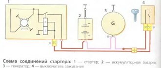
The electrical circuit for testing is assembled like this:
- a wire is pulled from the negative terminal of the battery and connected to the body (ground) of the generator;
- one wire from the light bulb is also connected to ground;
- the second wire is connected to the thread coming out of the generator and marked B+ on the body;
- The positive terminal of the battery is connected via a wire to a plug on the generator housing, marked with the letter D.
1 - battery, 2 - light bulb, 3 - generator
The check itself occurs as follows. After assembling the circuit, you need to start rotating the generator rotor. When rotated, it begins to generate and supply current to the light bulb, and it lights up. You can rotate it manually. However, those who doubt that manual rotation of the rotor can start the generator can do this using a drill or screwdriver.
When the light is on, it means everything is working properly. The absence of combustion indicates a malfunction, but what exactly it is cannot be said right away - further diagnostics are required.
It should be borne in mind that this method cannot check the performance of diode bridges, the absence of short circuits on the housing or in the winding. The technique only allows you to verify whether current is generated or not.
Replacing the VAZ 2107 voltage regulator relay
If the external relay of the VAZ 2107 generator breaks down, you should replace it with a new one. If the cause of the breakdown lies in the brushes, only the brush assembly must be replaced.
The old internal relay-regulator can be replaced with a new “three-level” one, which provides more reliable voltage stabilization, taking into account the temperature conditions and the load on the generator.
They are called three-level because of three pre-configured adjustment modes that can be switched manually. The switch itself is installed separately from the relay, in a place convenient for the driver and protected from moisture and dirt.
To avoid a short circuit, connect the ground wire to the battery only after installing the relay and power wires.
Not every driver knows what a VAZ 2107 charging relay is; in addition, this device is extremely rarely remembered. The charging relay is a voltage regulator or “chocolate bar” that is located in the generator. Owners of the Seven only pay attention to this detail after problems with the battery not charging begin. To prevent it from happening at one point, which negatively affects the engine, it is necessary to periodically monitor the operation of the charging relay.
Remote regulator unit
Purpose of the regulator relay VAZ 2107 injector and carburetor
The main purpose of the voltage regulator relay on the VAZ 2107, and any other car, is to maintain a stable and sufficient charging current for the on-board network and the car battery, as well as to level out voltage surges in the generator. Variations in the generated voltage would occur as the generator rotates at different frequencies. When the power drops below 12V, the battery stops charging, and the entire bot network no longer functions at 100%. If the voltage exceeds 16 Volts, this can lead to boiling of the battery, as well as failure of on-board devices.
On early production VAZ cars of the carburetor type, the voltage regulator is located on the left arch of the engine compartment. Such devices are also called external, since they were installed outside the generator structure. To be more precise, a brush mechanism was installed in the generator, and control was carried out via a printed circuit board, which was installed outside the product.
Most VAZ 2107 cars of the carburetor and injection type are equipped with generators with built-in charging relays. The charging relay on such VAZ 2107 vehicles is located directly on the side of the generator opposite the pulley.
Location on generator
To maintain an acceptable battery charge, the alternator requires 13.6 to 14.6 volts of power. The voltage regulation circuit is carried out using an electrical circuit, which is located on a printed circuit board (chocolate board) or in the form of a single semiconductor module (tablet) with brushes. The switch located inside the generator is usually not able to adequately respond to the ambient temperature due to its location close to the running engine. The built-in relay is sometimes replaced with a three-level voltage regulator, which is due to the greater efficiency of the product due to manual adjustment of the output voltage.
How to check the charging relay on a VAZ 2107
If you suspect a faulty operation of the voltage regulator relay, then you must first check the voltage at the battery terminals with the car running. The power supply must be no lower than 13 and no higher than 14.6 Volts. The reasons for such increased or decreased voltage can be caused by the following factors:
- charging regulator malfunction;
- failure of the generator itself;
- lack of contact in the electrical connections of the battery or generator.
Design and operating principle
The voltage regulator can be of several types: contact, electronic and three-level. The contact relay of the regulator can be missed, since it has not been used on VAZ cars for a long time. Today, the most popular is the electronic type voltage regulator. Its design includes a winding consisting of 1300 turns of wire. During operation, it magnetizes the metal core.
The factory resistance value for this relay is 17 ohms. If, when checking with a special device, the resistance level is lower or higher, this means that a short circuit occurs inside the relay.
The main component of the device responsible for voltage stabilization are resistors. During operation, switching occurs in them. Their device is designed in such a way as to withstand voltage drops of up to 80 Ohms.
The exception is the three-level regulator. It is installed separately from the electronic relay, instead of the generator brushes. In order to secure and connect this device to the VAZ 2107, you need to drill a small hole in the generator casing. The wires coming from the device must be inserted into this hole and connected in such a way that the three-level regulator and its control unit, located on the body ground, receive power from one source.
Three-level launch vehicle
Many may have the following question: “why is this device called “three-level”?” The answer is simple: when it operates, there are three standard operating modes: minimum (13.72 V), average (14.26 V), and maximum (14.75 V).
The three-level type differs from the electronic one in its purpose. On the VAZ 2107, there is such a problem as: during frosts, the battery does not hold a charge, and the generator does not charge it. So, in order to eliminate this problem, use a regulator of this type.