Brake system in Lada cars of the 2101-07 family
The braking system (TS) of any vehicle is designed to control the speed of movement, stop and hold it stationary for the required period of time.
It is one of the most important vehicle control systems, since road safety functionally depends on the degree of serviceability and efficiency of the braking system.
Summarize
The brake system of the VAZ-2107, like any other car, is an important component of an integral vehicle control system that ensures traffic safety.
Diagnostics and timely repair of vehicles is a vital necessity.
Let's first take a look at what brake systems are available in this car model. There are only two of them:
A working vehicle is used to allow the vehicle to reduce speed and stop. The parking lock fixes the vehicle in a stationary state when the driver needs it. They do not depend on each other, but setting off on a journey knowing that one of them is faulty is strictly prohibited. Naturally, the front and rear brakes should also always be replaced in a timely manner.
Braking system of modern cars
The general braking scheme on modern cars suggests the presence of three main types:
The working vehicle performs the functions of reducing the speed of the vehicle or stopping it.
The spare vehicle is intended to prevent malfunction or failure of the working system.
The parking vehicle performs the functions of holding the vehicle stationary in special conditions and in parking mode. The VAZ-2107 implements a working and parking vehicle in a “pure” form.
In a modern car, braking can be performed not only by the vehicle itself, but also by the engine, electric or hydraulic transmission brake. In addition, additional systems (or devices) are often implemented that increase the productivity of braking functions:
- anti-lock braking system (the notorious ABS);
- electric brake force distribution (or EBD);
- electrical stabilization system (ESP), etc.
The described devices and systems lead to a significant increase in the cost of the vehicle, and the VAZ-2107 brake system diagram does not provide for them.
However, domestic cars have recently begun to provide similar capabilities.
General structure of the working vehicle
The schematic diagram of the vehicle includes the following elements:
- brake mechanism;
- brake drive.
The brake mechanism implements the function of braking - achieving the torque that is necessary to reduce the speed of movement or stop.
The VAZ-2107 is equipped with a classic version of friction mechanisms based on friction force.
Their design can be represented by the following two options:
- disk (compression mechanism);
- drum (unclamping mechanism).
In the VAZ-2107, a disc mechanism is used on the front wheels, and a drum mechanism on the rear.
A brake actuator is needed to control the braking mechanisms. There are mechanical, pneumatic, hydraulic, electric and combined operating principles of drives. The VAZ-2107 uses the most common hydraulic principle, based on the action of brake fluid (a special oily substance).
The hydraulic drive circuit includes:
- brake pedal (to control the hydraulic drive);
- vacuum booster (to create additional force when pressing the pedal);
- master brake cylinder with an expansion tank (to ensure an increase or decrease in fluid pressure in the dual-circuit system, as well as to replenish fluid);
- wheel (or working) cylinders (to bring the control functions of the pedal to the brake mechanism);
- rear brake pressure regulator (to adjust the braking force as the vehicle weight increases);
- pipelines and hoses (for placing and moving brake fluid throughout the system).
The implementation of braking functions in the VAZ-2107 (as well as in related models - sedans 2101, 2103, 2105, 2106 and station wagons 2102, 2104) involves the use of two parallel independent hydraulic drive circuits. In the event of a malfunction of one circuit, the braking functions are redistributed to the second.
Brakes VAZ 2105 Zhiguli
- Repair manuals
- Repair manual for VAZ 2105 (Zhiguli) 1980-1992.
- Brakes
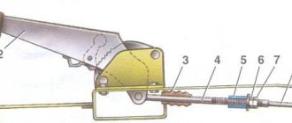
8.0 Brakes Brake system diagram 1 – brake disc;
2 – brake pedal; 3 – vacuum booster; 4 – master cylinder for hydraulic brakes; 5 – pipeline of the front brake drive circuit; 6 – front brake protective cover; 7 – front brake caliper; 8 – vacuum pipeline; 9… 8.1 Possible malfunctions, their causes and methods of elimination CAUSE SOLUTION METHOD Insufficient braking efficiency Leakage of brake fluid from the wheel cylinders of the front or rear brakes Replace unusable parts of the wheel cylinders, wash and dry the pads and drums, bleed the hydraulic drive system Air…
8.2. Checking and adjusting brakes (Category). See the list of materials inside...
8.3 Clutch and brake pedal bracket Details of the clutch and brake pedal bracket 1 – bracket; 2 – nut; 3 – spring washer; 4 – inner bushing of the brake pedal; 5 – outer bushings of the brake pedal; 6 – brake pedal; 7 – spacer sleeve; 8 – brake pedal release spring; 9 – outer bushings ped...
8.4 Vacuum booster The vacuum booster is attached to the plate of the clutch and brake pedal bracket on four studs 6 (see Fig. Vacuum booster) with nuts, and the main cylinder is attached to the vacuum booster on two studs 26. An outer rubber band is clamped between the body 2 and the cover 4 23 apertures, which divides ...
8.5. Master cylinder (Category). See the list of materials inside...
8.6. Front brakes (Category). See the list of materials inside...
8.7. Rear brakes (Category). See the list of materials inside...
8.8. Rear brake pressure regulator (Category). See the list of materials inside...
8.9. Parking brake (Category). See the list of materials inside...
↓ Comments ↓
1. Vehicle operation
1.0 Vehicle operation 1.1. Starting the engine 1.2 Controlling the gearbox 1.3 Driving the vehicle 1.4 Braking and parking 1.5 Operating a new vehicle 1.6 Adjusting the ignition timing 1.7 Precautions when operating the vehicle 1.8 Caring for the body 1.9 Storing the vehicle
2. Car maintenance
2.0 Vehicle maintenance 2.1 Maintenance operations
3. General information
3.0 General data 3.1 Technical characteristics of vehicles 3.2. Controls 3.3. Control of interior ventilation and heating 3.4 Tightening torques for threaded connections 3.5 Tools for repair and maintenance 3.6 Used fuels, lubricants and operating fluids 3.7 Basic data for adjustments and monitoring
4. Engine
4.0 Engine 4.1 Possible malfunctions, their causes and methods of elimination 4.2 Removing and installing the engine 4.3 Disassembling the engine 4.4 Assembling the engine 4.5 Bench tests of the engine 4.6 Checking the engine on the car 4.7. Cylinder block 4.8. Pistons and connecting rods 4.9. Crankshaft and flywheel 4.10. Cylinder head and valve mechanism 4.11. Camshaft and its drive 4.12. Cooling system 4.13. Lubrication system 4.14. Power system 4.15. Carburetor 2105-1107010 4.16. Carburetor 21051-1107010
5. Transmission
5.0 Transmission 5.1. Clutch 5.2. Gearbox 5.3. Cardan transmission 5.4. Rear axle
6. Chassis
6.0 Chassis 6.1. Front suspension 6.2. Rear suspension 6.3. Shock absorbers
7. Steering
7.0 Steering 7.1 Possible malfunctions, their causes and methods of elimination 7.2. Inspection, check and adjustment of the steering 7.3. Steering gear 7.4 Steering gear rods and ball joints 7.5 Bracket for pendulum arm
8. Brakes
8.0 Brakes 8.1 Possible malfunctions, their causes and methods of elimination 8.2. Checking and adjusting the brakes 8.3 Clutch and brake pedal bracket 8.4 Vacuum booster 8.5. Main cylinder 8.6. Front brakes 8.7. Rear brakes 8.8. Rear brake pressure regulator 8.9. Parking brake
9. Electrical equipment
9.0 Electrical equipment 9.1 Possible malfunctions, their causes and methods of elimination 9.2 Circuits protected by fuses 9.3. Battery 9.4. Generator 9.5. Starter 9.6. Ignition system 9.7. Lighting and light signaling 9.8. Sound signals 9.9. Windshield cleaner 9.11. Heater fan electric motor 9.12. Control devices 9.13. Carburetor pneumatic valve control system
10. Body
10.0 Body 10.1 Possible malfunctions, their causes and methods of elimination 10.2. Doors 10.3. Hood, trunk lid, bumpers 10.4. Body glazing, windshield and headlight glass washers 10.5 Instrument panel 10.6. Seats 10.7. Heater 10.8. Body frame repair 10.9. Paint coatings 10.10. Body anti-corrosion protection
11. Car modifications
11.0 Vehicle modifications 11.1. Features of repair of VAZ-21051 and VAZ-21053 cars 11.2. Features of repair of VAZ-2104 and VAZ-21043 cars 11.3 VAZ-21044 cars with a fuel injection system 11.4. Central fuel injection system design
12. Electrical circuits
12.0 Electrical diagrams 12.1 Interactive electrical diagram of the VAZ-2105 car 12.2 Electrical diagram of the VAZ-2104 car 12.3 Electrical connection diagram of the injection system 12.4 Connection diagram of the instrument cluster 12.5 Connection diagram of the brake system warning lamps 12.6 Connection diagram of the headlight cleaners and washers 12.7 Connection diagram of the heater fan motor 12.8 Diagram inclusion windshield cleaner and washer 12.9 Diagram for switching on direction indicators and hazard warning lights
Operating principle of a hydraulic working vehicle
The functioning diagram of the VAZ-2107 brake system is typical. Pressing the brake pedal (through the vacuum booster) moves the piston in the master cylinder, which creates fluid pressure and forces it to move through the pipelines to the wheel brake mechanisms.
Under the influence of fluid pressure, the cylinder pistons help move the brake pads of the front wheels to the discs, and the rear wheels to the drums. The result of the movement of the pads is their contact with the discs and drums and the slowing down of the latter. The friction force of the braking wheels with the surface of the roadway leads to a general slowdown of the vehicle.
The braking stop circuit involves releasing pressure on the brake pedal and moving the fluid back to the master cylinder. This means a drop in fluid pressure in the system and loss of contact between the pads and drums and discs, that is, the cessation of braking.
The same principle underlies the braking process on “classic VAZ models (from 2002 to 2106). The only exception that the VAZ-2101 system circuit has is the absence of a vacuum booster.
Absolute vehicle malfunctions
During operation, the braking functions of the system deteriorate. This is due to wear and tear of components, assemblies and parts that require repair. Some vehicle malfunctions are included in a special “List...”, and driving with them is prohibited.
Inefficiency of the working vehicle
The most common malfunction of the brake system (including the VAZ-2107) is inefficiency, which is diagnosed by two main parameters (when carrying out a specialized instrumental study):
- increasing braking distance;
- increase in steady deceleration during braking.
Relative vehicle malfunctions
This list of faults does not apply to absolute (or categorical) faults. Their presence is associated with the convenience (or inconvenience) of driving.
Increased hydraulic pedal travel (as an option - a “soft” pedal)
The reasons for the “sinking” of the pedal are determined by the presence of air in the system; extreme wear of brake pads; failure of the main or wheel cylinders. The action plan for eliminating technical problems includes checking and repairing all components and assemblies of the system; and, if necessary, replacing failed ones and bleeding the system.
Shift towards the vehicle's trajectory when braking
The malfunction is due to either a failure of the working (wheel) cylinder or wear of the pads. Replacing them (or repairing them) will solve the problem.
Increased background noise, friction (grinding) in the brake mechanism
Deficiencies are localized mainly in the rear mechanisms and are determined by contamination of the mechanism, critical wear of the pads, breakage of spring elements, uneven wear of discs or drums. Fault repair involves washing and replacing mechanism parts.
Vibration when braking
This is a fairly common malfunction that is associated solely with critical or uneven wear of the discs or drums, and the repair will consist of replacing them. » alt=»»>
Brake system VAZ 2107
The braking system on the “seven” ensures safety when driving. And if the engine is needed for movement, then the brakes are needed for braking. At the same time, it is very important that braking is also safe - for this purpose, the VAZ 2107 was equipped with brake mechanisms that use the friction forces of various materials. Why was this necessary? This was the only way in the 1970s and 1980s to quickly and safely stop a car speeding at high speed.
Brake system elements
The brake system of the “seven” consists of two main components:
- service brake;
- parking brake.
The main task of the service brake is to quickly reduce the speed of the machine until it comes to a complete stop. Accordingly, the service brake is used in almost all cases of driving a car: in the city at traffic lights and parking lots, when the speed of traffic decreases, when disembarking passengers, etc.
The service brake is assembled from two elements:
- Braking mechanisms are various parts and assemblies that have a stopping effect on the wheels, as a result of which braking occurs.
- The drive system is a series of elements that the driver controls to apply the brakes.
The “seven” uses a dual-circuit braking system: disc brakes are installed on the front axle, and drum brakes are installed on the rear axle.
The purpose of the parking brake is to completely lock the wheels on the axle. Since the VAZ 2107 is a rear-wheel drive car, in this case the wheels of the rear axle are blocked. Locking is necessary when the car is parked to prevent the wheels from moving arbitrarily.
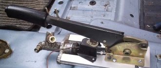
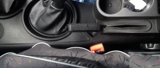
Adjusting the handbrake yourself
If you promptly ask yourself the question of how to tighten the handbrake on a VAZ-2107, and do all the work correctly, you will be able to avoid a number of unpleasant situations. Securely locked wheels will prevent the car from rolling away while parked. In addition, a properly functioning hand brake system makes it much easier to move the car away if you are on a steep road. Therefore, if the handbrake on a VAZ does not work effectively enough, read the instructions for adjusting it.
Timely tightening of the handbrake on the VAZ-2107 will allow you to avoid unpleasant situations
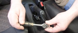
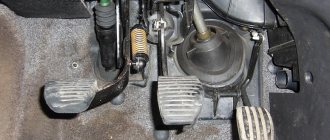
Before pulling the handbrake on the VAZ-2107, make sure that the brake pads of the rear wheels are in good technical condition. And also check the condition of the cable itself - perhaps it is too stretched or worn out and a regular tightening will not solve the problem. And also check the operation of the handbrake drive. If all parts are in good condition, prepare two “13” wrenches and pliers and begin adjustment, guided by the sequence of actions described below:
- The VAZ-2107 hand brake is adjusted under the bottom of the car, so it must be installed above the inspection hole or the rear of the car must be raised using a jack.
- Set the parking brake lever to the applied position by tightening it 5–6 clicks.
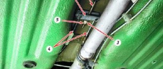
- After this, while under the car, remove all dirt from the adjusting rod and nuts. After cleaning, hold the adjusting nut with one wrench and loosen the lock nut.
- Next, by tightening the adjusting nut, you need to tighten the handbrake cable until the rear wheels lock. During the process, the adjusting rod should be held with pliers so that it does not rotate.
- After the required degree of cable tension has been set, tighten the nut a few more turns - this is necessary to reduce the free play of the lever.
- Now check if the wheels actually brake, and if everything is fine, you can tighten the lock nut.
If the handbrake tension is adjusted correctly, the brake pads will hold the car on a 25% slope.
Upon completion of the work, it would be useful to lubricate the threaded connections, for example, with lithol - this will make the adjustment process easier the next time. So, now you have learned how to tighten the handbrake on a VAZ-2107 car, but you still need to check the system in action. To do this, find a road section with a 25% slope (or a suitable overpass) and after stopping, pull the handbrake lever 2-4 clicks. If the tension is adjusted correctly, the brake pads will hold the car in place.
Basic faults
The most common malfunction of the VAZ 2107 brake system is the ineffectiveness of the braking itself. The driver himself can notice this malfunction by eye:
- when braking, the braking distance increases;
- The braking process itself takes longer than before.
This malfunction can be caused by a number of breakdowns:
- there are air pockets in the system;
- leakage of brake fluid;
- severe wear of the pads;
- cylinder failure.
For the VAZ 2107, the braking distance is determined: at a speed of 40 km/h on a flat and dry road, the braking distance should not exceed 12.2 meters until the car comes to a complete stop. If the path length is higher, then it is necessary to diagnose the performance of the brake system.
In addition to ineffective braking, other malfunctions may also occur:
- strong grinding noise (noise) when squeezing the brake pedal;
- the car swerves to the sides when slowing down;
- softened brake pedal lowered;
- vibrations and jerking when pressing the pedal.
The design of the VAZ 2107 brake system: main mechanisms
The 7's braking system contains many small parts. Each of them serves the sole purpose of protecting the driver and people in the cabin while braking or parking the car. The main mechanisms on which the quality and efficiency of braking depends are:
- master cylinder;
- amplifier;
- regulator;
- pads;
- disks;
- drums;
- pedal;
- highways.
Master cylinder
The master cylinder body works in direct connection with the amplifier. Structurally, this element is a cylindrical mechanism to which the brake fluid supply and return hoses are connected. Also, three pipelines leading to the wheels extend from the surface of the master cylinder.
Inside the master cylinder are piston mechanisms. It is the pistons that are pushed out under the pressure of the fluid and create braking.
The use of brake fluid in the VAZ 2107 system is explained simply: there is no need for complex drive units and the path of the fluid to the pads is simplified as much as possible.
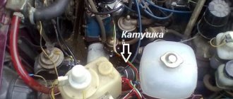
Vacuum booster
When the driver presses the brakes, the initial boost goes directly to the booster device. The VAZ 2107 is equipped with a vacuum booster, which looks like a container with two chambers.
Between the chambers there is a very sensitive layer - a membrane. It is the initial force—pressing the pedal by the driver—that causes the membrane to vibrate and create a vacuum and pressurize the brake fluid in the reservoir.
Brake operation diagramInitial position: system released
In the initial position, the brake pedal 47 is pulled back by the spring 32 until it stops at the tip 33 of the brake signal switch. The valve pusher 31, and with it the valve body 20 with the rod 17, are pressed out by the return spring 19 and are in the rearmost position (in the direction of travel of the car). The access of outside air to atmospheric cavity D is blocked, and vacuum cavity A freely communicates with cavity D. When the engine is running, a vacuum is created in both cavities, since vacuum cavity A is connected to the engine inlet pipe. Under the action of the return springs, push the pistons 11 and 15 of the main brake cylinder 14 to their rearmost position and rest against the limiting screws 8. The spacer rings 13, resting against the limiting screws, push the seals 9 to the forward position, opening passages for the brake fluid. The cavities of the master cylinder communicate freely with the cavities of the feed tank and the drive pipelines of both circuits. The pistons 4 of the wheel cylinders of the front brakes are pressed from the brake pads 2 by approximately 0.1 mm due to the elastic deformation of the sealing rings 3. The brake pads 2, without experiencing pressure from the pistons, remain only in light contact with the friction surfaces of the brake disc 1. When driving car without braking, the piston 36 of the pressure regulator is raised to its highest position until it stops with the protrusion of the head into the plug 35. The brake fluid can freely pass to the wheel cylinders 34 of the rear brakes. By the force of the tension spring, the brake pads 43 are pressed against the stops of the pistons 44. The pistons are pushed inside the wheel cylinders by the amount of free play (1.4-1.6 mm) and are rested by the nuts against the shoulder of the thrust rings 46. The force of the tension spring is not enough to move the thrust rings along cylinder mirror.
Start of braking
When a car moves with the engine running, a vacuum is created in cavities A and D of the vacuum booster, transmitted from the engine inlet pipe through hose K. The driver, pressing the brake pedal 47, moves the pusher 31 of the booster valve. The end of the valve 27, reaching the hole in the valve body 20, will close the annular slot and separate cavities D and A of the amplifier. The piston 26 of the amplifier valve moves forward, a gap appears between the piston and the end of the valve 27, which connects cavity D with the atmosphere. Filling the vacuum, outside air enters through the filter 30, passes between the front end of the pusher and the end of the valve and then through channel C enters cavity D, creating pressure on the valve body 20 through the diaphragm 21, dividing the amplifier into cavities, and thereby reducing the required driver effort on the brake pedal. The pressure developed on the valve body depends on the degree of vacuum in the engine intake pipe and on the force of pressing the brake pedal. The rod 17 also moves along with the valve body. Having selected the gap between the tip and the piston 15, the rod moves the piston forward. When moving away from the limit screw, the rear edge of the annular groove of the piston is pressed against seal 9 and separates the cavity of the front brake hydraulic drive from the cavity of the feed tank. From this moment, with further advancement of the piston 15 in the cavity of the hydraulic drive of the front brakes, the pressure of the brake fluid is transmitted through pipelines and brake hoses 6 to the inner wheel cylinders and then through connecting tubes to the outer wheel cylinders of the front brakes. Under the pressure of the brake fluid, overcoming the elastic deformation of the sealing rings, the pistons 4 extend from the wheel cylinders 5 until they come into contact with the brake pads. With a further increase in pressure, the brake pads clamp the brake discs 1, slowing down the rotation of the front wheels. If at this moment the driver stops pressing the pedal, but without removing his foot, leaves it pressed, then the valve body 20 will move forward under atmospheric air pressure by the amount of the gap between the thrust plate 25 and the piston groove 26. In this case, the released end of the valve 27, having reached to the end of the piston 26. will block the flow of atmospheric air into cavity D, and excess air pressure in cavity D will pass into vacuum cavity A through the newly opening annular slot, channel B and then into the engine intake pipe. The pressure in both cavities will be balanced and the servo action of the amplifier will stop. If you resume pressing the pedal 47, then under the influence of increasing pressure of the brake fluid in the cavity of the hydraulic drive of the front brakes, the piston 11 of the hydraulic drive of the rear brakes will begin to move. From the beginning of the piston movement, the same sequence of interaction of the parts associated with this piston will be repeated. The increasing pressure of the brake fluid in the cavity of the hydraulic drive of the rear brakes will be transmitted through pipelines to the pressure regulator and then to the wheel cylinders 34. Moving under the pressure of the brake fluid, the pistons 44 move apart and press the brake pads 43 against the friction surface of the brake drums. From the beginning of braking, the mass of the car tends to move forward, the load on the front suspension increases, and on the rear suspension decreases. Thanks to this, the rear of the body begins to rise, the short arm 42 of the regulator drive lever moves down, since the long arm of the lever associated with the rear axle beam (see sheets 23 and 25) copies the movement of the suspension. Piston 36, under pressure from brake fluid, overcomes the resistance of spring 40 and begins to descend.
Full braking
At the moment of complete braking of a moving vehicle, the maximum load transfer occurs from the rear suspension to the front and the greatest lift of the rear of the body occurs. The traction of the rear wheels with the road weakens. The piston 36 of the regulator, falling lower, comes into contact with its head with the seal 38 and shuts off the fluid supply to the wheel cylinders of the rear brakes. Further braking of the rear wheels is stopped, possible slipping of the wheels relative to the road and skidding of the car are prevented. Until the rear of the body lowers and the short arm 42 lifts the piston 36, it will remain pressed against the seal by the difference in forces applied to the piston head from two sides: from above, the pressure of the brake fluid in the wheel cylinders, multiplied by the area of the head; from below, the pressure of the brake fluid from the main brake cylinder, multiplied by the significantly smaller area of the lower flange of the head, as well as the compression force of the spring 40 and the twisting force of the drive lever. If the hydraulic drive circuit of the rear brakes fails, the pressure of the brake fluid developed when moving the piston 15 moves piston II all the way into the plug 48. In this case, the holes connecting the cavity of the hydraulic drive of the rear brakes with the feed tank and with the pipeline will be blocked, and brake fluid leaks will not occur. will occur, and the front brake hydraulic circuit will remain fully operational. In this case, only the full travel of the brake pedal and the braking distance of the car will increase. If the hydraulic drive circuit of the front brakes fails, piston 18 will move forward until it stops against piston 11, will close the compensation hole connecting the cavity with the nutrient tank, and with further pressing of the brake pedal will activate the hydraulic drive circuit of the rear brakes. The vehicle's full pedal travel and braking distance will also increase.
Disinhibition
If you release the pedal, it tends to return to its original position. The released pedal, by the force of the pull-out spring 32, pulls the pusher 31 and the piston 26. The piston, in contact with the end of the valve 27, closes the access of outside air to cavity D. The end of the valve extends from the edges of the hole for the piston 26 and opens a passage connecting cavity D with cavity A through channel B. The servo action of the amplifier stops, and the brake pedal, valve body 20 together with ii)current 17 return to their original position. Without experiencing pressure from the rod, pistons 11 and 15, under the action of return springs, move back, the original position is up to the limit screws 8. When returning, spacer rings 13, resting against the limit screws, move the seals 9 to the front wall of the annular groove of the pistons and communicate with the cavities master cylinder with feed tank. The pistons 4 of the front brake are retracted to the non-working position by reducing the elastic deformation of the sealing rings 3, and the pistons 44 of the rear brake are retracted by reducing the tension spring 49. Excess brake fluid flows through the compensation holes into the supply tank.
1. Brake disc. 2. Front brake pad. 3- Piston O-ring. 4. Wheel cylinder piston. 5. Front brake wheel cylinder. 6. Brake hose of the front brake drive circuit. 7. Brake pad mounting pin. 8. Piston stroke limit screw. 9. Seal. 10. Stop cup. 11. Rear brake drive piston. 12. O-ring spring. 13. Spacer ring. 14. Main brake cylinder. 15. Front brake drive piston 16. Seal. 17. Rod. 18. Vacuum valve. 19. Valve body return spring. 20. Valve body. 21. Diaphragm. 22. Vacuum booster housing. 23. Housing cover. 24. Rod buffer. 25. Piston thrust plate. 26. Piston. 27. Vacuum booster valve. 28. Valve spring. 29. Valve return spring. 30. Air filter. 31. Valve pusher. 32. Tension spring. 33. Brake signal switch tip. 34. Rear brake wheel cylinder. 35. Regulator housing plug. 36. Regulator piston. 37. Housing bushing. 38. Piston head seal. 39. Spring plate. 40. Piston spring. 41. Piston sealing ring. 42. Short arm of the lever driving the regulator. 43. Rear brake pad. 44. Piston of the rear brake wheel cylinder. 45. Piston seals. 46. Thrust ring. 47. Brake pedal. 48. Cork. 49. Tension spring.
Read more about VAZ 2105...
Read about all cars and vehicles
How to bleed the brake system
Bleeding the brakes on a VAZ 2107 (that is, eliminating air locks) may be required in several cases:
- after pouring new fluid into the tank;
- in the process of repairing any system unit;
- due to fluid leaks;
- due to a sharp decrease in braking efficiency.
Bleeding the system can restore the brakes' functionality and make driving safer. To work you will need:
- 8/10 socket wrench;
- open-end wrench 8/10;
- thin transparent hose;
- basin or bucket for waste liquid.
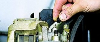
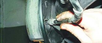
It is recommended that the work be carried out by two people: one person will depress the pedal in the cabin, the other will drain the liquid from the fittings.
- Fill the brake fluid up to about the reservoir.
How to change a handbrake cable
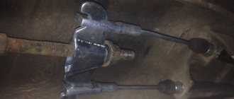
Not all car enthusiasts know that the parking brake system includes not one, but two cables - front and rear. It is the second one that often has to be changed. There may be several reasons for this, including critical wear and damage. And also in case of frequent jamming, the cable has to be replaced. In addition, if, after adjusting its tension, you find that the handbrake can no longer block the rear wheels, while the brake pads are fully operational, replacing the VAZ-2107 handbrake cable will be the only correct solution. We will tell you how to do this further.
If you do not intend to contact a car service, you can change the unusable cable yourself. To do this, you need to buy a new part and prepare the same simple set of tools that are used in the adjustment process. You will also need a jack.
The handbrake cable needs to be changed if it gets jammed frequently.
Important! Buy a handbrake cable only from a supplier that has proven itself and is trustworthy, since a low-quality product made in violation of technology will not last very long.
If everything you need is ready, you can start replacing, starting with dismantling. The following guide describes in detail how to change the handbrake cable on a VAZ-2107 in a garage - you just need to follow its instructions:
- First, you need to raise the rear of the car so that the rear wheels can rotate freely. This is necessary to dismantle the brake drums, without which removing the old cable and installing a new one is simply impossible.
- Now you need to remove the brake pads, and there is no need to remove both, but only the rear one on each wheel.
- Next, similar to the adjustment process, hold the adjusting nut on the rod with one wrench, and loosen the locknut with the second. But in this case, both nuts should be unscrewed. First, disconnect the tension spring from the rod using pliers.
- After removing the nuts, you can easily remove the rear cable guide, and then remove the cable itself from it.
- On the left and right sides of the car, two fixing brackets are attached to the bottom, in which the protective shell is placed - they must be removed by unscrewing two nuts on each.
- Further towards the wheels, the protective shell rests with two tips on two more brackets. There is no need to unscrew anything here - just disengage the tips by pulling the shell back.
- Having reached the brake flap on each wheel, remove the two bolts that hold the tips of the protective shell. Then pull the rope to bring them out.
Further, replacing the handbrake cable on a VAZ-2107 car involves installing a new product. To do this, follow the same pattern as when removing, but in reverse order. At the same time, make sure that the protective sheath passes over the longitudinal rod, and the right and left branches are located each on their own side, since they are not the same. So, on the shell of the right branch there is a rubber tube, but on the left it is missing. Before replacing the cable, it is advisable to install new brake pads, and after completing all installation work, be sure to adjust the hand brake system.
Operating a vehicle with a faulty brake system is prohibited. This also includes cases when the handbrake does not hold the car well or does not work at all. Therefore, repairing the VAZ 2107 handbrake is a job that should be performed immediately. If lifting the lever 5-6 clicks is not enough to lock the car in place, the handbrake requires attention.
- Raise the rear wheels using a jack or lift so that they can be rotated by hand.
- Tighten the handbrake 2-3 clicks (until the locking position).
- Use a wire brush to clean the threads on the adjusting bolt if they are dirty. If corrosion is severe, use WD-40 to remove the nut from the adjusting bolt.
- Using a pair of 13mm wrenches, loosen the locknut;
- Using a 13mm wrench and pliers, adjust the position of the nut so that the wheels are locked.
Note: if even in the extreme position of the nut the VAZ 2107 handbrake is not tightened sufficiently, it is necessary to replace the cable.
- Make sure that the cable is not overtightened and that when the lever is lowered, the wheels are unlocked.
- Tighten the locknut.
- Lubricate the threads of the adjusting bolt with lithol to prevent corrosion.
As you can see, applying the handbrake of the VAZ 2107 is quite simple.
When adjusting the handbrake, it is worth checking the rear wheel bearings. They should rotate easily and smoothly, without noise. The presence of play indicates the need to tighten the bearings.