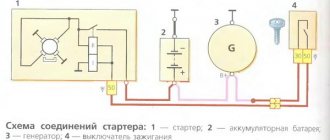
A modern car is densely saturated with numerous instruments and devices, the performance of which is determined by receiving power from the on-board DC network. When the engine is running, the current source is an electric generator, the rotor of which rotates due to the presence of a mechanical connection with the shaft. The engine speed varies widely, causing the generator output voltage to fluctuate. To reduce voltage variations to the required value, a stabilizer is installed at the output of the rectifier, which is made in the form of a relay regulator.
Car alternator output voltage problem
The list of functions of the generator necessarily includes recharging the on-board battery, which is carried out with a certain current to ensure a long service life. The simplest way to set its value is to slightly exceed the voltage taken from the output of the relay-regulator over the current value of the battery voltage. In this case, a serious problem immediately arises, which is due to the fact that, depending on the ambient temperature, the value of this excess should be different.
An obvious and fairly easily implemented solution to obtain a given output voltage using temperature correction of the regulator response threshold by installing an appropriate sensor is of low efficiency. The reason for this is that the temperature in the engine compartment, due to its proximity to a heated engine, differs from the air temperature, and it is not possible to determine the degree of this difference by simple means.
Another problem in determining the set value of the charging current is due to the fact that even at a constant ambient temperature, the load on the on-board network varies within wide limits. This leads to a “failure” in the battery charge level and difficulty starting a cooled engine after parking.
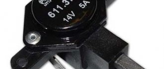
A good way to solve these problems is to switch to a relay-regulator, which makes the necessary adjustments by discretely changing the voltage that the generator creates. The specified value of the response threshold of this device is set by the driver independently using a three-position toggle switch. Some regulators connect automatically and contain an internal sensor that monitors the instantaneous value of the on-board network voltage. In both cases, the selection of the cutoff threshold is carried out taking into account external factors, primarily the current temperature and operating conditions of the vehicle.
SHI stabilizer
Pulse-width stabilizers are characterized by more stable operation, that is, an almost constant voltage is supplied to the vehicle network, and small deviations within the normal range are smooth. The device circuit uses the same parts as in the original, but at the same time the K561TL1 microcircuit is included. This made it possible to assemble a multivibrator and a short pulse shaper on the 1st node. The output switch control unit has also been simplified due to the use of a field-effect transistor with increased power.
Advantages of using a three-level relay and features of its installation
In practice, three-level regulators designed for the 9th and older VAZ models have become widespread. This is due to the fact that replacing the standard relay with a three-level one provides the following advantages:
- stabilization of alarm operation in severe frosts;
- increasing the brightness of headlights and interior lighting lamps;
- a sharp increase in the efficiency of the heater;
- increasing the speed of power windows.
Kits for VAZ “ten” and 14th models are quite common; there are also devices for “Volga” and “Gazelle”. Their use on these vehicles gives a similar effect.
A three-level relay-regulator is purchased in the form of a ready-to-install kit, which includes detailed illustrated instructions. The main elements of the kit are a contact group, a relay itself with a slide-type switch for selecting the stabilization voltage, and connecting wires.
Before starting replacement work, it is advisable to charge the battery and then disconnect its negative terminal.
The contact group of the new device is mounted directly on the seats of the previously dismantled old one; installation does not require the use of adapters and other auxiliary elements. The connecting wire is pulled through the generator cover (you may need to cut a hole in it to the required size), and the relay itself is attached to a free mounting stud with the terminals facing down. When installing, additionally check for reliable ground contact. After installing and assembling the generator, we check it.
Stories from our readers
“Fucking basin. "
Hi all! My name is Mikhail, now I’ll tell you a story about how I managed to exchange my two-wheeler for a 2010 Camry. It all started with the fact that I began to be wildly irritated by the breakdowns of the two-wheeler, it seemed like nothing serious was broken, but damn it, there were so many little things that really started to irritate me. This is where the idea arose that it was time to change the car to a foreign car. The choice fell on the melting Camry of the tenth years.
Yes, I had matured morally, but financially I just couldn’t handle it. I’ll say right away that I am against loans and taking a car, especially not a new one, on credit is unreasonable. My salary is 24k a month, so collecting 600-700 thousand is almost impossible for me. I started looking for different ways to make money on the Internet. You can’t imagine how many scams there are, what I haven’t tried: sports betting, network marketing, and even the volcano casino, where I successfully lost about 10 thousand ((The only direction in which it seemed to me that I could make money was currency trading on the stock exchange, they call it Forex. But when I started delving into it, I realized that it was very difficult for me. I continued to dig further and came across binary options. The essence is the same as in Forex, but it’s much easier to understand. I started reading forums, studying trading strategies. I tried it on a demo account, then opened a real account. To be honest, I didn’t manage to start earning money right away, until I understood all the mechanics of options, I lost about 3,000 rubles, but as it turned out, it was a precious experience. Now I earn 5-7 thousand rubles a day. I managed to get the car buy after half a year, but in my opinion this is a good result, and it’s not about the car, my life has changed, I naturally quit my job, I have more free time for myself and my family. You’ll laugh, but I work directly on the phone)) If If you want to change your life like me, then here’s what I advise you to do right now: 1. Register on the site 2. Practice on a Demo account (it’s free). 3. As soon as you get something on the Demo account, top up your REAL ACCOUNT and go to REAL MONEY! I also advise you to download the application to your phone, it’s much more convenient to work from your phone. Download here.
2. MAX - both diodes are used 3. MID - only diode D2 is used. In such a scheme, any switching is painless - in intermediate states of the toggle switch there will be mode No. 2.
I connected the red wire to the “In” terminal, and the black wire to the “Out” terminal.
- When toggle switch S1 is in position “1” , the generator operates in normal mode.
- In position “3” of toggle switch S1, one Schottky diode is connected. The voltage at the generator output increases by 0.3-0.4V.
- When toggle switch S1 is in position “2” , two Schottky diodes connected in series are connected to the generator circuit. The generator output voltage increases by (0.3-0.4V)*2.
The arrangement of parts in the case and the fastening of the metal strip on the case cover are shown.
To connect the box with diodes to the generator, I had to remove the plastic cover. I ran the wires through the slot in the generator cover.
- I soldered the male terminal to the red wire. It connects to the wire with the “mother” coming from the additional diodes of the diode bridge.
- I soldered the “mother” terminal to the black wire with the wire sealed at 90 degrees. This wire connects directly to the excitation terminal of the voltage regulator.
Having connected these wires to the generator circuit, we put the plastic cover in place and connect the standard wires going to the gene. This is what it looks like assembled:
Next, we screw the plastic box with diodes to the car body between the adsorber and the right headlight. To make it look better, we put plastic on the wire and lay it along the standard wiring and secure it with clamps.
Checking the work
- Switch position “min” - for operation at high ambient temperatures (above 20ºС), as well as during operation in particularly difficult conditions (traffic in traffic jams, long climbs in the mountains, etc.);
- The middle position of the switch is for operation at ambient temperatures from 0ºС to 20ºС;
- The “max” switch position is for operation at low ambient temperatures (below 0ºC), as well as for recharging a discharged battery.
Average load (PTF, dimensions, music and heater fan at first speed)
:
Maximum load, maximum number of consumers activated
:
Will you be installing a three-level voltage regulator on your car? Take part in the survey and leave your feedback in the comments.
Let us remind you that another reason for low voltage on the on-board network may be a bad ground.
Share on social networks:
Remote controller
ATTENTION! A completely simple way to reduce fuel consumption has been found! Don't believe me? An auto mechanic with 15 years of experience also didn’t believe it until he tried it. And now he saves 35,000 rubles a year on gasoline! Read more"
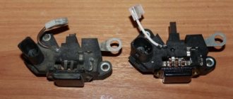
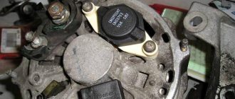
This often happens to drivers. The brushes of the generating device burn out. The regulator is built in along with the brushes. We have to change everything together. And here’s some advice from experts: it’s better to install an external regulator than a built-in one. The models released recently have not been praised very much.
Okay, do you think I’ll install an external one, but how do I connect it? It turns out that there is a convenient scheme that makes it easy to carry out all this modernization.
Some important points:
- do not confuse the chips on the regulator numbered 67 and 15 (the first should be connected to the generating device, and the second should go to the fuses);
This is what the connection diagram looks like
In the lower photo we see a diagram that shows the connection of the already built-in regulator relay.
It is suitable for connecting to “fives”, “sevens”, VAZ 2104, if the PG is installed from a VAZ “kopek”. As you can see, the remote-type regulator relay is connected via two terminals. Pin 15 goes to the fuse.
The second pin 67 is connected to the generator. The wire is connected to the brush chip.
Also, the remote-type relay must be connected to ground - any part of the body.
A relay is nothing more than a switch that serves to close and disconnect individual zones of an electrical circuit that occur at specific electrical values. A machine relay is otherwise called a load voltage switch, and this is 100 percent true. When the power supply unit, fan or starter consumes more current than necessary, the relay trips.
The relay consists of an electric type magnet, an armature and a switch. In this case, the electromagnet is a cable twisted around an inductor with a magnetic rod, and the armature is a special plate that controls the contacts.
As soon as electrical voltage passes through the magnet winding, an electric field is created. A special pusher presses the armature against the core and, thereby, the contacts switch.
Attention. There are two types of relays used on VAZ cars. This is a non-contact relay-regulator and MER (electric). It is the diagram of the last relay that is shown in the picture below.
The non-contact relay or NERR is a fairly new unit that does not require any additional adjustments or regulation. As for the MED, this is an old-style device, the production of which has currently been suspended.
So, the BRN or built-in regulator is a device consisting of a microcircuit, a transistor and a housing with brushes. If the built-in regulator fails, it is replaced with a new one, or an external one is installed.
The external regulator is easy to install if you strictly follow the instructions.
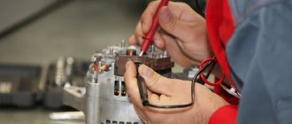
Modernization involves dismantling and disassembling the generating device.
Disadvantages of electrical equipment of the VAZ 2110
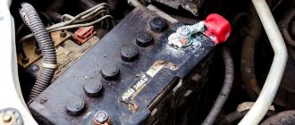
Where, exactly, do all the complaints about the battery come from? A good well-maintained battery will last five to seven long winters and no questions will arise about it if you charge it correctly, discharge it correctly and at least slightly monitor its condition. In the case when the battery is charged directly on board the car, which most often happens, the charging current strongly depends on the number of consumers on board.
The more of them, the stingier the generator becomes and pays less and less attention to the battery. He also needs to feed the voracious fog lights, a powerful audio system, additional comfort equipment, refrigerators, glass, mirror and seat heaters, and you never know what else the tuners come up with. And the generator is designed taking into account the rated charging current, without taking into account the additional load. As a result, the battery sits on starvation rations, is constantly undercharged, especially in winter, the plates crumble and after two years of grueling work asks to be thrown into a landfill. We blame the battery, of course. Only in vain.
How to remove RN
You can remove the old regulator without visiting a service station. To do this, you need to perform the following operations:
- Disconnect the terminals from the battery.
- Using a 10mm wrench, unscrew the nuts from the stud and disconnect the power cable.
- Unfasten the three latches on the plastic casing. After this, access to the regulator opens.
- Next, unscrew the two screws with a size 8 wrench and disconnect another wire.
- After this, you can remove the factory LV and install a 3-level one.
Please note that installation of a new generator occurs in the reverse order. There is only one feature: you need to bring out two wires for the control module. It is very important that the control module is secured very well and that there is no chance of moisture getting in there.
Which TRN is suitable for LADA
| Generator, article number | Automobile | TRG, article number |
| 26.3701, 37.3701, 371.3701, 372.3701 | VAZ-2107, -2108, -2109, -2110, OKA | 67.3702-01 |
| 3002.3771, 332.3771, 3202.3771, 3212.3771, 4302.3771, 94.3701, 9402.3701, 9422.3701, 3740.3771-38, 3743.3771-61, 3747.3771- 93, eld-a-21214, LG01214 | VAZ, GAZ | 67.3702-02 |
| 4052.3701, 409.3701, PRAMO “ISKRA” 5102.3771, -10, 5112.3771, -10, 5122.3771, -10, -30, 5142.3771, AAK 5727 | VAZ, GAZ, UAZ with generators PRAMO “ISKRA” 5102.3771, 5122.3771 | 67.3702-04 |
| G222 | VAZ-2104, -2105, -2107 | 67.3702-09 |
| 26.3701, 37.3701, 371.3701, 372.3701 | VAZ-2107, -2108, -2109, -2110, OKA | 67.3702-11 |
| 3002.3771, 332.3771, 3202.3771, 3212.3771, 4302.3771, 94.3701, 9402.3701, 9422.3701, 3740.3771-38, 3743.3771-61, 3747.3771- 93, eld-a-21214, LG01214 | VAZ, GAZ | 67.3702-12 |
| generators with an additional three diodes, the excitation winding of which is connected to the positive circuit | 673.3702 |