In our article we will look at the reasons why the starter of a VAZ-2107 or a similar car does not turn. In fact, all the malfunctions of this unit are the same on all machines. The design of the starters is the same, regardless of whether it is a Lada or a Toyota. There may be small differences in the design that are not very noticeable at first glance. But what to do if the starter fails? The first solution that may come to mind is to push the car and start it that way. But this is once, maximum twice, you won’t start the engine every time in such a difficult way! Therefore, in this article we will look at the design of the starter, its main breakdowns and methods for eliminating them.
What is a starter for?
You may be interested in:Best AGP video cards: description and characteristics
This is an electric machine that is needed to start the car engine.
In fact, the VAZ-2107 starter is a specially designed high-power electric motor. It works like this:
- The driver turns on the ignition and turns the key to the extreme position.
- The relay turns on, supplying power to the winding of the retractor.
- The power contacts are simultaneously closed and the gear moves to its extreme position until it engages with the flywheel ring.
- An electric motor rotates the crankshaft of the internal combustion engine.
You may be interested in:Dunlop Grandtrek SJ6 tires: review, characteristics and owner reviews
At the same time, all other devices that participate in the operation of the internal combustion engine are activated. High voltage is applied to all spark plugs, the fuel mixture is injected into the combustion chambers, and the engine starts and starts running.
VAZ 2101 starter connection diagram
- starter,
- holding winding of the traction relay,
- ignition switch,
- generator VAZ 2101,
- fuse box,
- pull-in winding of the traction relay,
- accumulator battery.
Under normal loads, the current generated by the starter is 150 A. When heavy loads occur, for example in winter, the resulting current can reach 500 A. This is a serious test for this electrical unit, so it is not recommended to keep the key on the start for more than 10 seconds, and repeated starting attempts must be made with a break of at least a minute.
Basic starter failures
Among the main breakdowns in which it is necessary to repair or replace the VAZ-2107 starter, the following can be identified:
It is worth noting that some breakdowns lead to the starter refusing to function at all. But there are also malfunctions in which the operation of the unit is still possible, but with some restrictions. For example, if the overrunning clutch is partially destroyed, you can observe how the starter rotates the crankshaft in jerks. Similar symptoms occur when the teeth on the flywheel crown are destroyed.
Bushings
These elements are located on both sides of the starter. Their task is to control the rotation of the shaft. If the bushings are too worn, then the starter will not start and will make clicking noises. Problems can arise if the starter is not installed correctly and is not in the right place. There could also be a short circuit in the winding.
Heavy cranking may indicate poor performance of the bushings, even if the power unit is warmed up.
The failure of the bushings is not a serious failure, but if you do not want to encounter a problem when the car refuses to start, then they need to be changed in time. Moreover, the bushings can cause the starter shaft to jam, which can lead to self-ignition.
How to understand that the starter has become unusable
Now let's talk about how to understand that the device is faulty and requires repair? The following signs of failure can be identified:
Now let's move on to repairing the starter mechanism on the VAZ-2107.
Brushes and winding
The starter design consists of four metal cores, which are also called shoes, and a winding connected into a circuit.
The voltage supplied to the winding comes from the central input. In turn, the output is output to positive copper-graphite brushes going to the commutator. They also connect negative brushes coming from the starter mass. Several small springs constantly press the brushes. Graphite is not a strong enough material, so sooner or later they break. When the life of the brushes comes to an end, the solenoid relay stops receiving voltage.
When such a problem occurs, the starter will not spin or make sounds. In case of repair, the unit is disassembled, the condition of the brushes is assessed and replacement is made. If the brushes can still fulfill their intended purpose, then the problem usually lies in the winding. When the winding is completely burned out, then the varnish coating should also burn out.
And the copper color turns black. In such a case, you can change the winding or replace the part with a new one.
How to remove the starter with your own hands?
In order to replace the VAZ-2107 starter or repair it, you will need to completely remove it.
To do this, you need to prepare keys for 13 and 10. The order of work is as follows:
As you understand, all work will be carried out in close proximity to the exhaust manifold, so you must first wait until the engine has completely cooled down.
Features of the design of the on-board network of the VAZ 2107
The “sevens”, like most modern cars, use a single-wire circuit for supplying electricity to electrical equipment. We all know that power to devices is supplied through only one conductor - the positive one. The other terminal of the consumer is always connected to the ground of the machine to which the negative terminal of the battery is connected. This solution allows not only to simplify the design of the on-board network, but also to slow down electrochemical corrosion processes.
Current sources
The vehicle's on-board network has two power sources: the battery and the generator. When the car engine is turned off, electricity comes into the network exclusively from the battery. When the power unit is running, power is supplied from the generator.
The nominal voltage of the on-board network of the “Seven” is 12 V, but depending on the operating mode of the engine, it can vary between 11.0–14.7 V. Almost all electrical circuits of the VAZ 2107 are protected in the form of fuses (fuse links). The main electrical appliances are switched on via a relay.
Wiring on-board network VAZ 2107
The combination of electrical devices into one common “seven” circuit is carried out using flexible PVA type wires. The current-carrying cores of these conductors are twisted from thin copper wires, the number of which can vary from 19 to 84. The cross-section of the wire depends on the strength of the current flowing through it. The VAZ 2107 uses conductors with the following cross-section:
- 0.75 mm2;
- 1.0 mm2;
- 1.5 mm2;
- 2.5 mm2;
- 4.0 mm2;
- 6.0 mm2;
- 16.0 mm2.
Polyvinyl chloride is used as an insulating layer, which is resistant to possible exposure to fuel and process fluids. The color of the insulation depends on the purpose of the conductor. The table below shows the connection wires for the main electrical components in the “seven”, indicating their color and cross-section.
All electrical devices of the VAZ 2107 have a single-wire connection
Table: connection wires for main electrical appliances VAZ 2107
| Connection type | Wire cross-section, mm2 | Insulating layer color |
| Negative terminal of the battery - vehicle ground (body, engine) | 16 | Black |
| Starter positive terminal - battery | 16 | Red |
| Positive contact of the generator - plus battery | 6 | Black |
| Generator - black connector | 6 | Black |
| Terminal on the generator “30” – white MB block | 4 | Pink |
| Starter connector “50” – starter relay | 4 | Red |
| Starter Start Relay - Black Connector | 4 | Brown |
| Ignition switch relay - black connector | 4 | Blue |
| Ignition switch output “50” – blue connector | 4 | Red |
| Ignition switch connector “30” – green connector | 4 | Pink |
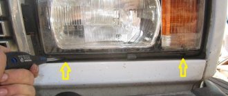
| Right headlight plug - ground | 2,5 | Black |
| Left headlight plug - blue connector | 2,5 | Green, gray |
| Generator output “15” – yellow connector | 2,5 | Orange |
| Right headlight connector - ground | 2,5 | Black |
| Left headlight connector - white connector | 2,5 | Green |
| Radiator fan - ground | 2,5 | Black |
| Radiator Fan - Red Connector | 2,5 | Blue |
| Ignition switch output “30/1” – ignition switch relay | 2,5 | Brown |
| Ignition switch contact “15” – single-pin connector | 2,5 | Blue |
| Right headlight - black connector | 2,5 | Grey |
| Ignition switch connector “INT” – black connector | 2,5 | Black |
| Six-pin block of the steering column switch - “ground” | 2,5 | Black |
| Two-pin block of the steering column switch - glove box illumination lamp | 1,5 | Black |
| Glove compartment light - cigarette lighter | 1,5 | Black |
| Cigarette lighter - blue block connector | 1,5 | Blue, red |
| Rear window defroster - white connector | 1,5 | Grey |
Find out more about the design of the VAZ 2107 generator: https://bumper.guru/klassicheskie-modeli-vaz/generator/remont-generatora-vaz-2107.html
Bundles (harnesses) of wires
To facilitate installation work, all wires in the car are collected in bundles. This is done either with adhesive tape or by placing the conductors in plastic tubes. The bundles are connected to each other using multi-contact connectors (pads) made of polyamide plastic. To be able to pull wiring through body elements, it is provided with technological holes, which are usually closed with rubber plugs that protect the wires from rubbing against the edges.
The “seven” has only five wiring bundles, three of which are located in the engine compartment, and the other two are in the cabin:
- right harness (stretches along the mudguard on the right);
- left harness (stretched along the engine shield and mudguard of the engine compartment on the left side);
- battery harness (comes from the battery);
- a cluster of the instrument panel (located under the dashboard, and goes to the headlight and turn switches, the instrument panel, and interior lighting elements);
- rear harness (stretches from the mounting block to the aft lighting fixtures, glass heater, fuel level sensor).
There are only five wiring harnesses in the VAZ 2107
Mounting block
All wiring harnesses of the “seven” converge to the mounting block, which is installed in the right rear part of the engine compartment. It contains fuses and relays for the machine's on-board network. The mounting blocks of carburetor and injection VAZ 2107 are almost the same structurally, however, in “sevens” with distributed injection there is an additional relay and fuse block, which is located in the cabin.
The main mounting block is located in the engine compartment
In addition, there are machines equipped with old-style blocks designed for the use of cylindrical fuses.
Old "sevens" have mounting blocks with cylindrical fuses
Let's consider what protection elements ensure the safe operation of the VAZ 2107 on-board network.
Table: VAZ 2107 fuses and the circuits they protect
| Designation of an element on the diagram | Rated current (in old-style/new-style units), A | Protected electrical circuit |
| F-1 | 8/10 | Heating unit fan motor, rear window defroster relay |
| F-2 | 8/10 | Electric wiper motor, headlight lamps, front window washer electric motor |
| F-3 | Not used | |
| F-4 | ||
| F-5 | 16/20 | Rear window heating element |
| F-6 | 8/10 | Clock, cigarette lighter, radio |
| F-7 | 16/20 | Signal, main radiator fan |
| F-8 | 8/10 | Turn signal lamps when the hazard lights are turned on |
| F-9 | 8/10 | Generator circuit |
| F-10 | 8/10 | Signal lamps on the instrument panel, the instruments themselves, turn signal lamps in the turn signal mode |
| F-11 | 8/10 | Interior lamp, brake lights |
| F-12, F-13 | 8/10 | High beam lamps (right and left) |
| F-14, F-15 | 8/10 | Dimensions (right side, left side) |
| F-16, F-17 | 8/10 | Low beam lamps (right side, left side) |
Table: VAZ 2107 relays and their circuits
| Designation of an element on the diagram | Switching circuit |
| R-1 | Rear window heating unit |
| R-2 | Electric motors for windshield washer and wiper |
| R-3 | Signal |
| R-4 | Radiator fan motor |
| R-5 | High beam |
| R-6 | Low beam |
The turn relay in the “seven” is installed not in the mounting block, but behind the instrument panel!
As already mentioned, the injection “sevens” have an additional relay and fuse block. It is located under the glove box.
The additional block contains relays and fuses for power circuits
It contains power elements that ensure the operation of the main electrical circuits of the car.
Table: fuses and relays of the additional mounting block VAZ 2107 injector
| Name and designation of the element on the diagram | Purpose |
| F-1 (7.5 A) | Main relay fuse |
| F-2 (7.5 A) | ECU fuse |
| F-3 (15 A) | Fuel pump fuse |
| R-1 | Main (main) relay |
| R-2 | Fuel pump relay |
| R-3 | Radiator fan relay |
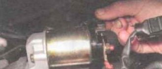
More information about the VAZ 2107 fuel pump: https://bumper.guru/klassicheskie-modeli-vaz/toplivnaya-sistema/benzonasos-vaz-2107-inzhektor.html
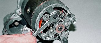
Starter disassembly and repair
Now let’s move on to disassembling the VAZ-2107 starter with our own hands. This is not difficult to do, you will need the most common tool, no special pullers or devices: a screwdriver, pliers, a 10mm wrench. In other words, everything that is available in any garage.
The disassembly procedure looks like this (briefly):
Replace worn elements and reassemble in reverse order. Usually it is not necessary to completely disassemble the device; it is enough to change the brushes and copper bushing at the rear of the rotor.
Unit repair
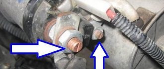
According to experts, the service life of the starter is up to 6 years. If this unit has been in regular use for several years and has stopped working, then it should be carefully checked. Regardless of the cause of the breakdown, the first thing that needs to be done is to conduct a visual inspection to identify visible problems.
You should carefully inspect the contacts, since often the starter stops working precisely because of them. An unstable charge can also cause the starter to fail to turn, so you need to try starting the car several times.
But even if the car starts, you should not assume that the breakdown resolved itself. Sooner or later the car will stop starting and the breakdown will need to be solved in a radical way. Simply replacing the starter may not always solve the problem.
To remove a part for subsequent disassembly you need:
Replacing bushings
To replace the bushings, you should increase the gap formed between the shaft and the support. The cause is often a misalignment that causes the rotor to touch the plate on the stator. The defect is solved by replacing the part.
These elements supply voltage to the rotor, or rather its winding.
Instructions for replacing brushes:
Relay repair
This unit is necessary for the gear to move along the rotor. The element is located on the body of the unit.
First, the control relay is checked. The screw securing the part should be tightened thoroughly to check for oxide on the wire and plates.
To test the relay you need to close the drive directly. The unit must be replaced with a new one if the rotor rotates.
If the unit is working properly, the resistance on the coils is 75 - 55 Ohms. If it does not meet these indicators, then they need to be changed, since they cannot be repaired.
Assembly and installation
To assemble the unit, you must perform the same steps, only in reverse order. Correctly install the cotter pins and corkscrew rings that are provided in the design of some elements. Check the node for functionality.
What if the flywheel crown is worn out?
If the crown has been ordered to live for a long time, then this can be felt in the literal sense of the word after removing the starter. Run your hand over the teeth and assess the degree of wear. If you need to change the crown, this is done after removing the gearbox. Carefully knock off the old crown from the flywheel. If it is being removed for the first time, then you can cheat a little and put it on the other side. The teeth are only half worn, so you can reuse the part to save money. This will save you 300-400 rubles, but if you want to install a new crown, do it. The new one is still stronger than the old one.
But you will have to warm it up on gas for several minutes; there are no other ways to install it on the flywheel. Carefully put the crown on, press it and wait a few seconds for the metal to cool and press the flywheel tightly. There is no point in removing the latter; everything can be done quickly enough if you have an inspection hole or overpass. After the work has been completed, check the operation of the starting mechanism; the starter should not feel any obstacles when rotating the rotor.
Source
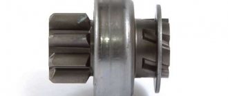
Bendix
This part is a more advanced analogue of the flywheel engagement unit, which begins to unwind after turning the ignition key. After the engine starts, the gear goes away. Bendix is also necessary for the normal operation of the solenoid relay.
If this unit is acting up, then when igniting it should make a loud crunching sound. In such a case, the starter should be dismantled, disassembled and checked:
- Turn the gear clockwise with your fingers. If the Bendix is working, then the gear should turn hard and be slightly spring-loaded.
- Now you need to scroll in the opposite direction. If the bendix is to blame, then you will succeed. If it is working, then the gear should remain in place even with serious force.
Starter circuit for VAZ 2110, 2111, 2112
Starters of type 57.3708 were installed on VAZ-2110 cars and had the following technical characteristics:
- Rated power 1.55 kW
- Current consumption at maximum power no more than 375 Amperes
- Current consumption in the inhibited state is no more than 700 Amperes
- Current consumption in idle mode no more than 80 Amperes
Connection diagram for the motor from the washing machine
The connection diagram for the starter for the ten is shown above, here is its explanation:
- battery
- generator
- the starter itself
- egnition lock
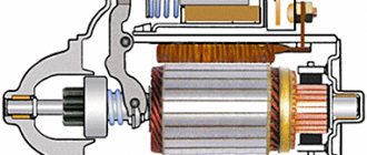
| 1 – drive shaft, | 20 – contact bolts, |
| 2 – front cover bushing, | 21 – output of “positive” brushes, |
| 3 – restrictive ring, | 22 – bracket, |
| 4 – gear with the inner ring of the overrunning clutch, | 23 – brush holder, |
| 5 – overrunning clutch roller, | 24 – “positive” brush, |
| 6 – drive shaft support with liner, | 25 – armature shaft, |
| 7 – planetary gear axis, | 26 – tie rod, |
| 8 – gasket, | 27 – back cover with bushing, |
| 9 – lever bracket, | 28 – collector, |
| 10 – drive lever, | 29 – body, |
| 11 – front cover, | 30 – permanent magnet, |
| 12 – relay anchor, | 31 – armature core, |
| 13 – holding winding, | 32 – armature shaft support with liner, |
| 14 – retractor winding, | 33 – planetary gear, |
| 15 – traction relay, | 34 – central (drive) gear, |
| 16 – traction relay rod, | 35 – carrier, |
| 17 – traction relay core, | 36 – gear with internal teeth, |
| 18 – contact plate, | 37 – layering ring, |
| 19 – traction relay cover, | 38 – hub with the outer ring of the overrunning clutch. |
VAZ 2106 starter connection diagram
- starter,
- generator,
- accumulator battery,
- pull-in winding of the traction relay,
- ignition switch,
- traction relay holding coil
| 1 – drive side cover, | 14 – relay cover, |
| 2 – retaining ring, | 15 – contact bolts, |
| 3 – restrictive ring, | 16 – collector, |
| 4 – drive gear, | 17 – brush, |
| 5 – overrunning clutch, | 18 – armature shaft bushing, |
| 6 – drive ring, | 19 – cover from the collector side, |
| 7 – rubber plug, | 20 – casing, |
| 8 – drive lever, | 21 – shunt coil of the stator winding, |
| 9 – relay anchor 2106, | 22 – body, |
| 10 – holding winding of the traction relay, | 23 – stator pole fastening screw, |
| 11 – pull-in winding of the traction relay, | 24 – anchor, |
| 12 – relay coupling bolt, | 25 – armature winding, |
| 13 – contact plate, | 26 – intermediate ring. |