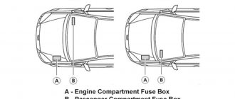
Location of fuse and relay boxes
Positions 1 and 2 for right-hand drive vehicles are located on the right side
- Fuse holder B -SB-
- Relay and fuse box 1 -SR1-
- Fuse holder A -SA-
Fuse block for battery, A -SA- (3)
3 - Glow plug control unit -J179- (Only for vehicles with diesel engine) 3 - Additional coolant pump relay -J496- (depending on equipment)
| № | A | Function/component |
| -SA1- | 150 | Generator -C-Not used1) |
| -SA2- | — | Not used |
| -SA3- | 110 | Ignition and starter switch -D- Light switch -E1- Steering column control unit -E595- X-pin safety relay -J59- Fuel pump relay -J17- Fuel pressure switch -J643- Low beam relay -J331- Fuse 20 in the fuse block B -SB20- Side light relay -J3- Power relay terminal. 30 -J317- Fuse 3 in fuse block B -SB3- |
| -SA4- | 50 | Power steering unit -J500- |
| -SA5- | 40 | ABS control unit -J104- |
| -SA6- | 40 | Radiator fan control unit -J293- Radiator fan -V7- |
| -SA7- | 50 | Glow plug control unit -J179- |
| -SC1- | 25 | ABS control unit -J104- |
| -SC2- | thirty | Radiator fan control unit -J293- Radiator fan -V7-Radiator heat fan -F18-1) |
| -SC3- | — | Not used |
| -SC4- | 10 | ABS control unit -J104-Not used1) |
| -SC5- | 5101) | On-board control unit -J519- (T73b/59) |
| -SC6- | 251) | Not used Automatic transmission control unit -J217-1) |
1) since May 2015
Passenger compartment fuse box B -SB- (1)
| Left-hand drive vehicles | Right hand drive cars |
| № | A | Function/component |
| 1 | — | Not used |
| 2 | 10 A | Steering column control unit -E595- Rear window wiper motor -V12- Windscreen and rear window washer pump -V59- |
| 3 | 57,56) | Fuel pump relay -J17- Engine control unit -J623- Onboard power supply control unit -J519-6) • Start switch -D-6) Fuel pump control unit -J538-6) Fuel pressure sensor -J643-6) |
| 4 | 27,56) | Steering column switch unit -E595-1) Multifunction steering wheel control unit -J453-1) |
| 5 | Not used | |
| 6 | 5 A | Control unit in instrument cluster -J285-Not used6) |
| 7 | 5 156) | Headlight range adjustment -E102- License plate light, left -X4- License plate light, right -X5- Switch and instrument panel light dimmer -E20-1) |
| eight | 10 A | Cylinder 1 injector -N30- Cylinder 2 injector -N31- Cylinder 3 injector -N32- Cylinder 4 injector -N33-Not used4) |
| nine | 5 7,51) | ABS control unit -J104- ASR and ESP switch off button -E256-1) Steering column switch block -E595-1) Tire pressure indicator button -E492-6) |
| 10 | 57,56) | Vehicle speed sender -G68- On-board control unit -J519- (T73a / 44) • Ignition and starter switch -D-Radio -R-6) |
| eleven | 5106) | Headlight range adjustment -E102- Left headlight depth adjustment drive -V48- Right headlight depth adjustment drive -V49- Steering column control unit -E595-1) Headlight range control unit -J431-6) Instrument panel combination -KX2-6) • Instrument cluster control unit -J285- |
| 12 | 57,5 | Exterior mirror adjuster -E43-Exterior mirror, driver's side -VX4-6) Exterior mirror, passenger's side -VX5-6) |
| 13 | 15 106) | Automatic transmission control unit -J217- Multifunction switch -F125- Selector lever -E313- |
| 14 | 5156) | Airbag control unit -J234- Switching off the airbag warning light PP -K145- 1) |
| 15 | — | Not used |
| 16 | 5106) | Parking assistance control unit -J446-4) is not used) |
| 17 | 10 A | Lambda probe heater -Z19- Lambda probe 1 heater after catalytic converter -Z29- Reservoir solenoid valve 1 -N80-Windscreen and rear window washer pump -V59-6) |
| 18 | 57,56) | Instrument cluster control unit -J285- Right fog light bulb -L47- |
| 19 | 57,56) | Side light relay -J3- Main unit -R- Vehicle control unit -J519- (T73a / 42) • Start switch -D- |
| winds | 5106) | Instrument cluster control unit -J285- Steering column switch unit -E595-1) Main relay -J271-5) Power relay cl. 30-J317-7) |
| 21 years old | 10156) | On-board control unit -J519- (T73a / 66) • Reading light, driver's side -W19- • Interior lighting with switch-off delay -W15- • Reading light, front passenger's side -W13- • Luggage compartment light, right -W35- • Rear center reading light -W44- |
| 22 | 5106) | Diagnostic connector -U31- Climate control unit -J301- Climatronic control unit -J255- Ignition key removal solenoid valve -N376- Rain and light sensor -G397- Side light relay -J3- Heated exterior mirror relay -J99- |
| 23 | 7,5 · 106) | On-board control unit -J519- (T73b / 39) Engine control unit -J623- Automatic transmission control unit -J217- Selector lever -E313-Rain sensor -G213-4) |
| 24 | 156) | Not used Onboard power supply control unit -J519-6) • Heated exterior mirror, driver's side -Z4- • Heated exterior mirror, passenger side -Z5- • Heated exterior mirror relay -J99- |
| 25 | 5156) | High pressure sensor -G65- Air conditioning relay -J32- Climate control unit -J301- Diagnostic connector -U31- Electrochromic interior mirror -Y7-4) Climatronic control unit -J255-6) Radiator fan control unit -J293-6) Compressor control valve air conditioner -N280-6) |
| 26 year | 5 7,53) 206) | Power steering unit -J500- Air mass meter -G70-Air conditioning relay -J32-6) |
| 27 | 5156) | Reversing light switch -F4- |
| 28 year | 156) | Not used Lambda probe 1 after catalytic converter -GX7- • Lambda probe -G39- • Lambda probe heater -Z19- Lambda probe 1 before catalytic converter -GX10- • Lambda probe after catalytic converter -G130- • Lambda probe heater 1 after catalytic converter -Z29- Injector cylinder 1 -N30- Injector cylinder 2 -N31- Injector cylinder 3 -N32- Injector cylinder 4 -N33- Canister solenoid valve 1 -N80- Glow plug control unit -J179-7) |
| 29 | 10154.6-7) 206-5) | Fuel pressure regulator -N276- Fuel metering valve -N290-Ignition coil 1 with end stage -N70-4.5) Ignition coil 2 with end stage -N127-4.5) Ignition coil 3 with end stage -N291-4.5) Ignition coil 4 with end stage stage -N292-4.5) Output stage -N122-8) Ignition coil -N152-8) |
| thirty | 10 | Coolant circulation pump 2 -V178- Exhaust gas recirculation radiator switching valve -N345- Charge pressure control solenoid valve -N75- Not used6) |
| 31 year | 10156) | Fuel pressure switch -J643- Glow plug control unit -J179-Injector cylinder 1 -N30-4.5) Injector cylinder 2 -N31-4.5) Injector cylinder 3 -N32-4.5) Injector cylinder 4 -N33-4.5) Ignition coil 1 with end stage -N70- Ignition coil 2 with end stage -N127- Ignition coil 2 with end stage -N127- Ignition coil 3 with end stage -N291- Ignition coil 3 with end stage -N291- Ignition coil 4 with end stage -N292- Ignition coil 4 with end stage -N292- Charge pressure control solenoid valve -N75-7) Switching valve, exhaust gas recirculation cooler -N345 -7) Coolant circulation pump 2 -V178-7) Charge pressure control solenoid valve -N75-7) Switching valve, exhaust gas recirculation cooler -N345 -7) Coolant circulation pump 2 -V178-7) |
| 32 | 30 A | Engine control unit -J623- |
| 33 | 5106) | Clutch pedal switch -F36- Brake light switch -F- Radiator fan control unit -J293-Air conditioning relay -J32-6) |
| 34 | 7.5 A 151) 206) | Right main beam lamp -M32- Left main beam lamp -M30-1) Control unit in instrument cluster -J285-1) |
| 35 year | 10 A | Engine control unit -J623-Not used6) |
| 36 | 15 A 201.6) | Fuel supply pump -G6- Fuel pressure switch -J643-Fuel pump relay -J17-6) |
| 37 | — | Not used |
| 38 | 7,5306) | Left high beam lamp -M30- Control unit in instrument cluster -J285-Automatic transmission control unit -J217-6) |
| 39 | 10156) | Low beam lamp, right -M31- |
| 40 | 30 A | Fresh air blower switch -E9- Fresh air blower control unit -J126- |
| 41 years old | Not used | |
| 42 | 15206) | Cigarette lighter -U1- |
| 43 years old | 15206) | Onboard power supply control unit -J519- (T73b / 13) • Front left turn signal lamp -M5- • Front right turn signal lamp -M7- • Rear left turn signal lamp -M6- • Rear right turn signal lamp -M8- • Left brake lamp - M9- • rear right turn signal lamp -M8- • right brake lamp lamp -M10- • high brake lamp lamp -M25- |
| 44 year | 5 A 101.6) | Ultrasonic alarm sensor -G209- Alarm siren -H12-Intrusion sensor -G578-6) Horn -H8-6) |
| 45 | 15306) | Main unit -R- Multimedia system control unit -J650-1) |
| 46 | 20306) | On-board control unit -J519- (T73a / 73) • High tone -H2- • Low tone -H7- |
| 47 | 20306) | On-board control unit -J519- (T73a / 68) • Wiper motor -V- |
| 48 | 25306) | On-board control unit -J519- (T73a / 16) • Driver's door central locking control -F220- • Front passenger's door central locking control -F221- • Rear left door central locking control -F222- • Rear right door central locking control -F223- • Trunk lid lock drive -F256- • Fuel filler flap lock motor -V155- |
| 49 | 5156) | On-board power supply control unit -J519-2) • Left reversing lamp -M16- • Right reversing lamp -M17- |
| 50 | 25306) | Driver's door control unit -J386-Left front window switch -E40-6) Driver's door window motor -V147-6) |
| 51 | 25306) | Front passenger door control unit -J387-Front passenger door power window switch -E107-6) Front passenger window motor -V148-6) |
| 52 | 30 A | Rear left door control unit -J388- Rear right door control unit -J389-Left rear door power window switch -E52-6) Rear right power window switch -E54-6) Rear left power window motor -V26-6) Rear left power window motor right window -V27-6) |
| 53 | 30 A | On-board control unit -J519- (T73b / 67) • Heated rear window -Z1- |
| 54 | 15206) | Left fog light bulb -L22- Right fog light bulb -L23- |
| 55 | 15 A | Ignition coil 1 with end stage -N70- Ignition coil 2 with end stage -N127- Ignition coil 3 with end stage -N291- Ignition coil 4 with end stage -N292- Not used4,6) |
| 56 | — | Not used |
| '57 | 57,56) | Left headlight bulb -M1- Left rear light -MX3- |
| 58 | 57,56) | Front right light bulb -M3- Right rear light bulb -MX4- |
| 59 | 10156) | Left low beam bulb -M29- |
| 60 | 156) | Not used Left daylight -L174-6) Right daylight -L175-6) |
1) Depending on the configuration. 2) Only for vehicles with automatic transmission. 3) From November 2010 4) From August 2011 5) Only for cars with a petrol engine 6) From May 2015 7) Only for cars with a diesel engine Only for cars with a petrol engine (overload 9) Only for cars with a gasoline engine 1.6 liter engine (aspirated) from May 2015.
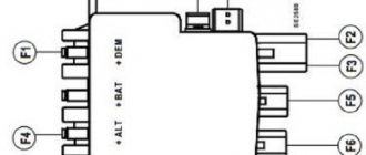
Fuse Box Diagrams
Dashboard
On a right-hand drive car, this panel is mirrored.
Assignment of fuses in the instrument panel
ampere part
| F1 | 5A | Instrument panel control unit ABS control unit Mobile phone control electronics control unit |
| F2 | 10A | Steering column combination switch On-board power supply Cleaner engine rear window Windshield and rear window washer pump |
| F3 | 5A | Fuel pump relay Engine control unit relay deposit fuel lock fuel pump control unit body sound control unit |
| F4 | 2A | (2A) Combination switch |
| F5 | – | – |
| F6 | 5A | Device control module |
| F7 | 5A | Headlight range control Left headlight license plate Right headlight license plate On-board power supply |
| F8 | 10A | Engine management system |
| F9 | 5A / 7.5A | TCS and ESP button Tire pressure monitor display sensor Steering angle ABS control unit System stop/start button Data bus diagnostic interface |
| F10 | 5A | Cruise control switch Steering column combination switch Brake light switch Clutch pedal On-board power supply |
| F11 | 5A/10A | Angle adjustment headlight leveling motor for headlight leveling, left headlight leveling motor for headlight leveling right headlight Cruise control switch On-board power supply control unit Turning light and headlight bezel control unit |
| F12 | 5A | Rearview mirror adjustment switch |
| F13 | 5A | Transmission Control Module (TCM) |
| F14 | 5A | Supplemental Restraint System (SRS) control unit |
| F15 | 5A | Hydraulic nozzles with heated windshield |
| F16 | 5A | Parking assistance control module |
| F17 | – | – |
| F18 | 5A | Rear fog lamp contact switch Control unit in the instrument panel Rear left fog lamp lamp On-board power supply |
| F19 | 5A | Multifunctional control module |
| F20 | 5A | Steering wheel angle sensor Control unit in instrument panel Fuel supply relay Fuel supply relay terminal 30 relay Low thermal power relay high voltage |
| F21 | 10A | Multifunctional control module |
| F22 | 5A | Diagnostic connector of the control unit control unit air conditioning control unit air conditioning control unit mobile phone control electronics Ignition key removal lock solenoid |
| F23 | 5A | Selector lever Rain sensor Onboard power supply control unit Engine control unit Data bus diagnostic interface |
| F24 | 5A | On-board power supply Heated outside mirror, driver's side Heated outside mirror, front passenger |
| F25 | 5A | High pressure sensor Heater control unit Radiator fan control unit Air conditioning control unit trailer detector check Diagnostic connector Humidity sensor Radiator fan control unit Stabilizer voltage stabilizer 2 |
| F26 | 7.5 A | Mass air flow meter oil level and temperature sensor steering control unit crankcase ventilation heating element Starter relay 1 Starter relay 2 |
| F27 | 7.5 A | Reversing lights |
| F28 | 10A | Engine management system |
| F29 | 10A | Engine management system |
| F30 | 10A | Engine management system |
| F31 | 5A/10A | Engine management system |
| F32 | 10A / 15A / 20A / 30A | Engine management system |
| F33 | 5A | Clutch position sensor Brake light switch |
| F34 | 15A | Control unit in the instrument panel left high beam lamps right high beam power control unit on board left exhaust lamp control unit unloading devices right gas dimming |
| F35 | 15A/20A | Engine management system |
| F36 | 7.5 A | Right high beam |
| F37 | 25A | Seat heating control unit |
| F38 | 30A | Transmission Control Module (TCM) |
| F39 | 10A / 15A | Right low beam |
| F40 | 30A | Air conditioner/heating fan control module |
| F41 | 10A | Rear window wiper motor |
| F42 | 15A | Cigarette lighter socket 12V |
| F43 | 15A | Multifunctional control module |
| F44 | 5A | Notification system |
| F45 | 15A | Audio system |
| F46 | 20A | Headlight washers |
| F47 | 20A | On-board power supply Wiper motor |
| F48 | 25A | Multifunctional control module |
| F49 | 15A/30A | Fuel pump relay Fuel relay |
| F50 | 25A | Driver door function control unit |
| F51 | 25A | Passenger door function control unit |
| F52 | 30A | Rear left door control unit Rear right door control unit |
| F53 | 30A | Multifunctional control module |
| F54 | 15A | Front fog lights |
| F55 | 15A/20A | Engine management system |
| F56 | 15A | Daytime Running Lights |
| F57 | 15A | Multifunctional control module |
| F58 | 20A | Brake booster vacuum pump |
| F59 | 10A / 15A | Left low beam |
| F60 | 15A | Audio system |
Main fuse box
Assignment of fuses in the main fuse block
ampere part
| SA1 | 150A/175A | generator |
| SA2 | 30A | Gas fuel control module |
| SA3 | 110A | |
| SA4 | 50A | Power steering control module |
| SA5 | 40A | ABS control module |
| SA6 | 40A | Coolant Fan Motor Control Module |
| SA7 | 50A | Glow plugs |
| SC1 | 25A | ABS control module |
| SC2 | 30A | Coolant Fan Motor Control Module |
| SC3 | 5A | Coolant Fan Motor Control Module |
| SC4 | 10A | ABS control module |
| PC5 | 5A | Multifunctional control module |
| SC6 | 30A | Transmission Control Module (TCM) |
Block under the hood
The fuse and fuse link mounting block is mounted on a plastic holder above the battery in the engine compartment.
Scheme
Description
| 1 | 25A ABS control unit |
| 2 | 30A Cooling fan motor control unit, cooling fan motor |
| 3 | 5A Cooling fan motor control unit |
| 4 | 10A ABS control unit |
| 5 | 5A Electrical package control unit |
| 6 | Reserve |
| SA1 | 150/175A Generator |
| SA2 | Reserve |
| SA3 | 110A Ignition switch, lighting switch, steering column switches, ignition switch contact relief relay, fuel pump relay, fuel supply relay when opening the driver's door, low beam headlight relay, fuse circuits 4, 20, 56, parking lights relay, power supply relay terminal 30 |
| SA4 | 50A Power steering control unit |
| SA5 | 40A ABS control unit |
| SA6 | 40A Cooling fan control unit |
| SA7 | Reserve |
Volkswagen Polo interior unit relay
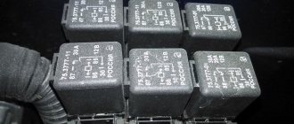
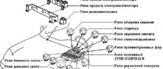
All relays in the car are located on a separate mounting block, which is located in the dashboard on the left side of the driver.
- R4 - pressure gasoline supply relay.
- R3 - starter blocking relay.
- R9 - air conditioning relay.
- R7 - relay for headlights. See fuses 57 and 58.
- R8 - fuel pump relay.
- R5 - power relay.
- R6 - spare seat.
- R10 - relay contact “X”.
- R1 - reserve seat.
- R11 - R15 are reserved.
- R2 - windshield heating relay. See fuse 56.
Cigarette lighter repair
The standard device is a collapsible module - in fact, it can be repaired if a malfunction is detected. On a VW Polo, the unit does not need to be repaired. The parts are sold assembled and are cheap.
Usually the entire part is removed from the car and replaced with a known good one.
Causes of cigarette lighter failure
Among the common occurrences, factors stand out.
- Use of the device for purposes other than its intended purpose. Individual drivers often use the device as a charger or power source for powerful consumers. The device cannot withstand the load and fails.
- Short circuit in the network. Water ingress, damage to wiring and loosening of contacts provoke short circuits and failure of the unit.
- Careless use of the device. Each unit must be operated carefully. Over time, the fasteners and body of the device may become deformed.
How to remove and disassemble the cigarette lighter
The principle of the procedure is the same for cars 2011-2016. The bottom line is that the design of the part is quite primitive and does not require modification.
To disassemble the cigarette lighter you will need to follow a sequence of steps.
- Disconnect the car.
- Using a special tool or a “homemade device”, press out the core fastening terminals.
- After this, remove the cigarette lighter from the plastic socket.
- Next, you will need to disconnect the terminal of the contact group and dismantle the device.
- The next step is to remove the plastic casing of the device. To do this, you need to take an awl or a thin screwdriver and pry off the expansion clamps.
- After this, the socket can be removed and the contacts from the backlight bulb disconnected.
Troubleshooting the food chain
On 2022 cars, some users encountered problems with the cigarette lighter line. Similarly, faults can appear in older cars.
To find and eliminate the malfunction, the entire circuit must be completely checked. The procedure begins with diagnosing the fuse. Next, the power line and the cigarette lighter itself are diagnosed.
Changing the backlight bulb
In rare cases, the light on the cigarette lighter burns out. To replace the illuminator lamp, you will need to dismantle the device and disassemble its housing. A standard lamp of a fairly common standard size is used inside.
Block "B" and instrument panel relay block
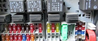
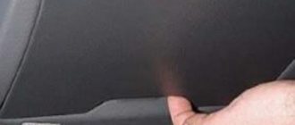
The larger fuse box B is located inside the vehicle. It is located under the steering column. Access is not difficult. Just lower the lid and the sesame will open. For ease of working with devices, small tweezers are built into the socket of the mounting block of the Volkswagen Polo sedan.
The layout looks a little more confusing than previous configurations. Therefore, if you have to replace “plugs” in a block, it is better to have a drawing on hand with a detailed designation of each element.
It’s immediately worth noting the fuses that “go” to reserve: 1.5.28−31.41.60. In addition, slots can be “reserved”: 8 and 32. “Otto” can be used to protect engine injectors and connector “32” for the fuel pump.
Lighting devices include a group of devices that consume large amounts of energy:
- contact “21 °” is responsible for the interior lighting and luggage compartment (10A).
- The reversing light switch in the right lamp is switched off thanks to slot 27 (5A).
- "Fog" - 54 (15A).
- Brake lights and direction indicators - 43 (15A).
- The dimensions of the left headlight and left rear light are 57 (5A).
- Right headlight: high beam - 34 (7.5 A), low beam - 39 (10 A).
- Rear fog lamp - socket 18 (5A).
- Left headlight: high beam - 38 (7.5 A), low beam - 59 (10 A).
- The direction of the headlight beams is determined by special regulators. Two fuses are used for them: the “seventh” (also checks the glow of the numbers) and the “eleventh” (starts the gearmotors in the headlights). Both elements have a current strength of 5A.
- The dimensions of the right headlight and right rear light are 58 (5A).
Several fuses control the engine and drive at the same time: 3 (5 A), 13 (15 A) and 23 (7.5 A). The electrical circuit of the control unit includes fuses that control various vehicle functions. This group may include:
- Side light relay and main sound reproduction unit 19 (5A).
- Heated rear view mirrors - 24 (5A).
- Central locking and fuel filler neck - 48 (25A).
- Windshield washer motor - 47 (20A).
- Heated rear window - 53 (30A).
- Heated seats - 37 (25A).
- Automatic transmission and speed switch - 13 (15A).
- Sound signal - 46 (20A).
- Speed sensor, ignition switch and automatic selector - slot 10 (5A).
- Heated windshield - 56 (40A).
A large group consists of “plugs” that protect the heating and air conditioning system: 22 (5A), 25 (5A) and 40 (30A). The steering column switches include the following fuses: 2 (10A), 4 (2A), 20 (5A).
In total, the “plug” of the interior circuit has 60 connectors. It is difficult to remember the location of each element, so it is recommended to check the position of the fuses before replacing a damaged link.
An important condition when replacing contacts is the current strength, which must be observed during the procedure. In other words, a jumper designed for a different current cannot be inserted into the connector. It is also strictly forbidden to use the fruits of “handicraft” developments. The “homemade products” themselves will burn out, and some of the electronic equipment of the Polo sedan will also be “taken” with them. And in the worst case, a fire that could leave the owner of a German car with nothing.
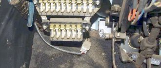
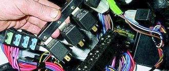
Finally, the last part of the car's wiring is the relay, located on the side of the dashboard. To remove it from the panel, you need to lift the side cover with a flat-head screwdriver and remove it. Rock the device from side to side and carefully pull it out of the hole.
The relay has 15 contacts. The last five in the chain are not used. The rest is responsible for the operation of the starter, lobovukha heater, fuel pump, low beam headlights, air conditioning compressor, and so on. If the source of the problem is in this box, we find the broken contact and change the necessary relay on it.
Thus, two conclusions can be drawn. Firstly, if one of the car components fails, you should first inspect the fuse and relay blocks - perhaps the cause of the malfunction lies in their visibility range. This will save money spent on the services of specialists at the gas station. Secondly, replacing burnt out elements will not cause problems even for a novice polo expert. It is only important to have a traffic jam diagram at hand.
Helpful information
There are a few things you need to know about fuses:
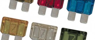
- the machine should always have suitable fuses of each type in reserve;
- Repairing this part is strictly prohibited;
- installing an unsuitable or repairable fuse can cause a fire, electrical failure or an accident;
- You cannot install fuses designed for a higher current supply than the factory part.
To protect yourself, it is important to remember that you cannot replace a removed fuse with any available parts, even for a short period of time.
Checking the health of fuses
If any vehicle device fails, it is necessary, using Tables 1 and 2, to determine which fuses are served by this element. Then you need to turn off the ignition.
In some cases (failure of the engine control unit, generator, side lights, cigarette lighter, etc.), it is better to remove the negative terminal of the battery. Then, using special dielectric pliers (you can use pliers), you need to disassemble the necessary fuses.
Testing fuses without removing them from the block may give an erroneous result.
Fuses in transparent housings can be checked visually. It should be remembered that this method of fault monitoring does not have a 100% guarantee, since sometimes it is not possible to see a microcrack in the conductive insert.
It is best to use the multimeter in the "diode", "resistance" or "continuity" test positions. The resistance value of a good fuse is approximately zero. The resistance of a blown fuse tends to infinity (the multimeter displays “1”).
Removal and replacement process
To replace, you will need a multimeter, a slotted screwdriver and a 10 mm wrench.
Under the hood
To replace the fuse in block C, simply remove the cover from it, unfasten the plastic latches and pull out the blown element with your fingers. For block A the procedure is more complicated:
- Press the latch and open the MB cover.
- Check the condition of the fuses:
- Switch the multimeter to ohmmeter mode.
- Apply one probe to each terminal in turn, and the second to the L-shaped metal plate. If the device shows 1 or infinity, this means that the fuse link connected to the terminal has burned out.
- Unscrew the 5 nuts securing the terminals and disconnect them.
- Unscrew the nut on the C block side and press the plastic lock on the battery side.
- Remove the power fuse block.
- Install the removed elements in reverse order.
Fuses and relays in the interior of a Volkswagen Polo sedan
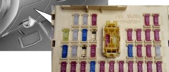
The fuse box is located at the driver's feet, at the bottom of the instrument panel, under the steering wheel. The block is closed with a protective cover, inside of which there is usually a circuit for the fuse box.
Fuse box diagram for Volkswagen Polo sedan
Identification of fuses from the block cover
Description
| 1 | To book |
| 2 | 10/15A Steering column switches, washer pump, rear wiper motor |
| 3 | 5/7.5A Fuel Pump Relay, Engine Control Module |
| 4 | 7.5A Steering wheel switches |
| 5 | To book |
| 6 | 5A Instrument panel control unit |
| 7 | 5/15A Beam Direction Controller, License Plate Light |
| eight | Injectors 10A or reserve |
| nine | ABS control unit 5/7.5A, ASR/ESP switch |
| 10 | 5 / 7.5 A Main unit, vehicle speed sensor, automatic transmission selector, transmission control unit, ignition switch |
| eleven | 5A Light beam direction regulator, gear motors in headlight units |
| 12 | 5A Rearview mirror adjustment joystick |
| 13 | 15A Automatic transmission control unit, automatic transmission multifunction switch, automatic transmission selector |
| 14 | Airbag control unit 5 / 10A |
| 15 | 5A Windshield washer nozzle heating elements |
| 16 | Parking sensor control unit 5/10A |
| 17 | 10/15A Lambda and clan probe heating evaporative system |
| 18 | 5 / 7.5A Control unit in instrument cluster, fog light in left rear light |
| 19 | 5 / 7.5 A Parking light relay, main audio unit, electrical control unit, ignition and starter switch |
| winds | 5 / 10A Control unit in instrument cluster, steering column switches |
| 21 years old | 10 / 15A Powerpack control unit, directional lighting, interior lighting with switch-off delay, luggage compartment lighting |
| 22 | Diagnostic connector 5/10A, climate control unit, climate control unit, ignition key lock solenoid |
| 23 | 7.5 / 10A Central electrical unit, engine control unit, automatic transmission control unit, automatic transmission switch (manual mode) |
| 24 | 5A Powertrain control unit, resistors for exterior mirrors |
| 25 | 5 / 7.5A Refrigerant pressure sensor, air conditioning compressor relay, cooling fan control unit, climate control unit, diagnostic connector, heating and ventilation control unit, diagnostic connector |
| 26 year | 7.5/10A Power steering control unit |
| 27 | 5/15A Reverse light switch in right rear light |
| 28 year | Lambda probe 10A |
| 29 | Ignition coils 20A |
| thirty | 15A Canister Solenoid Valve, Coolant Pump, Radiator Switch Valve Exhaust Gas Recirculation |
| 31 year | Cylinder injector 10A |
| 32 | 10A Fuel Pump, 30A Engine Control Unit |
| 33 | 5A Clutch pedal position sensor, brake light switch 10A Radiator fan control unit |
| 34 | 7.5A Right block - headlight (high beam) 20A High beam |
| 35 year | 10A Engine control unit |
| 36 | 10/15A Fuel Pump or Injectors 20A Highway Head Fuel Relay |
| 37 | 25A Driver seat heating controller, front passenger seat heating controller, front seat heating controller |
| 38 | 7.5A Left block - headlight (high beam), instrument panel control unit 30A Automatic transmission control unit |
| 39 | 10 / 15A Right headlight (low beam) |
| 40 | 30A Heater Fan Switch, Heater Fan Control Module |
| 41 years old | Rear wiper motor 15A cup |
| 42 | Cigarette Lighter Fuse 15/20A Volkswagen Polo Sedan |
| 43 years old | 15 / 20A Electrical accessories control unit, direction indicators, brake warning lights |
| 44 year | Ultrasonic theft detector 15A, anti-theft siren |
| 45 | 15 / 30A Navigation control unit, main audio unit, multimedia system control unit |
| 46 | 20 / 30A Power supply control unit (beep) |
| 47 | 20 / 30A Electric unit (wiper motor) |
| 48 | 25A / 30A Central locking, Tailgate lock actuator, Fuel flap motor |
| 49 | 5/15A Reversing light |
| 50 | 25 / 30A Driver door control unit |
| 51 | 25 / 30A Front passenger door control unit |
| 52 | 30A Rear left door control unit, Rear right door control unit |
| 53 | 30A Heated rear window |
| 54 | 15A Fog light |
| 55 | Ignition coils 15A |
| 56 | Heated windshield relay 40A |
| '57 | 5 / 7.5 A Side lamps in the left headlight and in the left rear lamp |
| 58 | 5 / 7.5 A Side lamps in the right headlight and in the right rear lamp |
| 59 | 10 / 15A Left lock - headlight (low beam) |
| 60 | Daytime running lights 15A |
The interior relays are located inside the control panel. To access it, you need to remove the cover from the end of the control panel on the driver's side.
Location
In a 2012 car, the required element is located at number 42 and has a rating of 15 A. In other modifications, the fuse can be installed in a different location.
The photo above shows where the fuse is located in the most popular modification common in the CIS.
Connection diagram
Fundamentally, the connection diagram of the device is no different in the sedan, hatchback or station wagon version. Below is the electrical part and the complete connection cycle of all components of the cigarette lighter power circuit.
For ease of perception, the highway is highlighted in blue.
Fuse blocks "A" and "C"
The fuse circuit is quite simple. Block A and block C are located on the Volkswagen Polo battery. Who did you miss? That's right, block B. It was hidden under the steering column in the car. In addition, inside the instrument panel on the left side there is a relay unit, an additional support for other control participants.
Has the generator stopped working or has the cooling fan stopped working on the Polo sedan? Then we go up to block A. It is in it that the fuses are located that are responsible for both parts of the car.
To access the mounting block, you need to press the lid latch and remove the “cap”. Under the cover we will find 7 fuses. First of all, the generator passes current through itself. Its power ranges from 150-175A. Next comes the ignition switch, steering column switches and various relays (low beam, fuel pump, etc.). The rated current of the fuse is 110A. Next comes the electric power steering control unit (50A), ABS and cooling system fan (40A each). Two places reserved.
Help with voltage redistribution is provided by block C. To access it, you need to disconnect the plastic clips on the sides in the engine compartment and remove the cover. 6 more fuses will burn out in front of us. Their circuit to some extent repeats that installed in block A.
Up to two slots: the first and fourth slots are responsible for the aforementioned ABS control section (25 and 10A respectively). The second and third slots control the cooling fan motor. The fifth is aimed at the correct operation of the electrical control unit. The last connector is a spare one.
Sources
- https://vmiredorog.com/tehpomosch/189-predohraniteli-i-rele-v-volkswagen-polo-sedan/
- https://moto-sol.ru/diagnostika-i-remont/folksvagen-polo-gde-predohraniteli.html
- https://AvtoMonitor.ru/predohraniteli-vw-polo-5.html
- https://avtoblokrele.com/blok-predohranitelej-i-rele-volkswagen-polo-sedan/
- https://rent-cabriolet.ru/remont/folksvagen-polo-gde-nahodyatsya-predohraniteli.html
- https://shassik.ru/transmissiya/predohraniteli-polo-sedan.html
- https://fuse-box.ru/predohraniteli-i-rele-volkswagen-polo-6r-mk5-2009-2017/
- https://venteler.ru/fol-ksvagen-polo-predokhranitel-konditsionera-gde-nakhoditsya-sedan/
- https://knigaproavto.ru/shemy/volkswagen/polo/366-perechen-predohraniteley-volkswagen-polo-s-2010.html
- https://zilart-auto.ru/remont/gde-nahodyatsya-predohraniteli-na-folksvagen-polo-sedan.html
Video “Replacing fuses on Polo”
The author ALEKS Black is replacing the inserts on the previous generation Polo hatchback. Replacing fuses on the Polo Sedan follows an identical pattern.
Do you have any questions? Specialists and readers of the AUTODVIG website will help you ask a question
Was this article helpful?
Thank you for your opinion!
The article was useful. Please share the information with your friends.
Yes (80.00%)
No (20.00%)
X
Please write what is wrong and leave recommendations on the article
Cancel reply
Rate this article: ( 5 votes, average: 4.80 out of 5)
Discuss the article:
How to remove and disassemble the cigarette lighter
A device equipped with such functions is found in any modern car, including the Volkswagen Polo sedan. Any car enthusiast knows where this device is. Drivers often use this device for purposes other than its intended purpose, resulting in breakdowns.
The locking device is simple. The cigarette lighter consists of:
- Connector for connection.
- A metal part that includes a special spiral.
The operating principle is also simple. When the button is pressed, the circuit closes, causing heat. The device has a special relay that turns off the system when the maximum temperature is reached. The circuit is open, heating stops.
Using the cigarette lighter, you can charge gadgets using special adapters. This element may fail if you connect devices that require high voltage.
The second most common malfunction is a loosening of the socket in which the receiver is located.
The cigarette lighter has 3 wires. Red is considered the main color. Another yellow wire is connected directly to the light filter, which is responsible for the correct operation of the backlight. The black wire goes last.
The most common malfunction is a broken wiring; the cigarette lighter will not work in this situation. In some cases, wires burn out due to sudden voltage surges.
The problem may arise due to oxidation of the contacts.
Sometimes the cause of a breakdown is a burnt-out element.
Repair
When the fault is resolved, the cigarette lighter must be replaced. Because of this:
- The ignition is turned off, the hood opens to access the terminals and remove the negative terminal.
- Small scissors with curved ends are inserted into the mandrel and removed along with the block. You can make the process easier if you press on the locking elements.
- Then the filter latches are retracted.
- Then a new part is installed in this place. Repairing an old element is rarely done.
Where is the fuse located
The Volkswagen Polo cigarette lighter fuse is located under the steering wheel on the right side in the first row from the edge. The fuse box is closed on top with a special plastic cover. Any driver can easily find this device without a hint. Fuse boxes in Volkswagen 2012 and 2013 problems are located there.
Check and replacement
It is difficult to replace a device without available tools if it does not work. To do this, it is more convenient to use pliers or tweezers. Determining where this part of the car is located is not so difficult - it is always blue.
The replacement procedure is as follows:
- The cover is carefully removed.
- Below is a fuse block, among which it is necessary to determine the one that is responsible for the operation of the cigarette lighter.
- Its power is 15 A. The insert must be replaced with exactly the same part.
This car has a standard fuse for the cigarette lighter.
The most common malfunction of a device is the formation of a defect when it overheats. It's easy to pick out this little detail. A working fuse has a transparent body, so the metal wire is clearly visible through it. It will be complete. Faulty - wire break.
There are fuses with opaque housing. In this case, the element has a special window through which the spiral is clearly visible. If its integrity is damaged, the part must be replaced. You can repair the fuse yourself.
Improved Polo cigarette lighter illumination
Users of cars manufactured before 2010 often complain that the backlight of the standard device is not enough - the device is invisible in the dark. As an improvement, the modern market offers options.
- Replacing the standard lamp with a brighter one. In this case, a diode illuminator of similar power is ideal.
- Installing another cigarette lighter. In stores you can buy a factory version of the cigarette lighter, suitable for mounting under the car.
- Replacing the case with a model of a different color.
