In what situations is replacement necessary?
Wear of the element is characterized by such manifestations as cracks or tears in the canvas, worn teeth and uneven edges. If you ignore such a deplorable state of a very important element, it will come back to haunt you with overheating and boiling of the engine, independent operation of the battery, which will lead to its rapid discharge.
If the belt is severely worn, it also shows signs of noise to the owner - it begins to whistle, especially at low speeds. The next reason for a whistling belt may be water getting on its surface, which occurs due to worn-out pipes of the cooling system - antifreeze begins to leak.
Some belts - oak ones - whistle when the car starts in frosty weather, and after warming up the sound is lost. A weak tension is expressed by a whistle, but in this case it is quite easy to overtighten.
how to remove the generator
from a
VAZ
of the traditional model range.
More details: 2107
.html Subscribe!
Examination
You can check the functionality of the generator without dismantling it. Before checking, the following steps must be taken:
- Disconnect the terminals from the battery, clean them, replace them and tighten them tightly.
- Clean terminal “30” of the generator. Check the wire of this terminal for damage to the insulation and repair any defects.
- Check belt tension. It is better to install a new belt to avoid slipping on the pulleys.
Particular attention is paid to the ground terminal. It must be disconnected and the area of attraction must be cleaned with sandpaper. The terminal, bolt and washer are also cleaned.
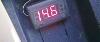
Next you need to check the battery charge level. To do this, you will need a multimeter in voltmeter mode to measure DC voltage. The charge of a working battery varies from 11 to 12.5 volts. Next you need:
- Start the power unit.
- Check the voltage on the battery while the generator is running.
- If the voltage gradually drops, this indicates a complete absence of incoming charging current.
- A voltage above 14.5 volts will indicate a high charge current, which can lead to boiling of the battery.
If the charging current is sufficient, varying within 14.5 volts, then while the power unit is operating, you need to turn on the car’s lighting and repeat the measurement. A powerful generator should not respond to the connection of new consumers by reducing the charge current. If this happens, then the mechanism should be tested after preliminary dismantling.
The following will describe how to check the generator during operation. To check you need:
- Set the multimeter to DC current measurement mode.
- Connect the red test probe to terminal “30” of the charging mechanism.
- Connect the black test probe to ground.
- A working generator should produce at least 14.3 volts DC. If there is no voltage, then you need to switch the multimeter to AC measurement mode. The results that appear will indicate a breakdown of the diode bridge.
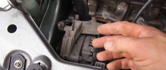
Further checks of the alternator will require removing the unit from the vehicle. This requires:
- Loosen the tension bolt.
- Move the generator towards the engine.
- Remove the transmission belt from the pulleys.
- Unscrew the fastening bolt.
- Dismantle the generator, first disconnecting all wires.
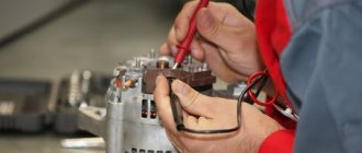
Next you need to disassemble the device. The following items can be checked with a multimeter: rotor, stator, charging relay, brushes, diode bridge and capacitor. The following will describe how each element is checked.
Rotor
The generator rotor is based on a copper inductor. It is hidden under metal protection. All these elements are mounted on the shaft. To check you need:
- The multimeter is switched to resistance measurement mode.
- The red dipstick connects to the first ring on the shaft.
- The black dipstick connects to the second ring on the shaft.
Both rings are located directly behind the outer bearing. The operating resistance of the coil should be no more than 5 ohms. If there is no resistance, then the part is considered unsuitable for use. High resistance will indicate a short circuit. The verification procedure is as follows:
- The multimeter is switched to dialing mode.
- The tester's red probe connects to the first slip ring.
- The black probe connects to the rotor housing.
The buzzer will indicate a breakdown of the coil winding on the housing. If there is no buzzer, then ring 2 must be checked. The test is performed in the same way. If the test does not reveal any malfunctions, then it is necessary to clean off the resulting oxidation, dirt and rust from the surface of the body. It is also worth checking the condition of the bearings. Elements with large play must be replaced.
The stator rings play an important role. It is necessary to clean them from dirt, oxidation and adhering graphite particles. The surface of the rings must be perfectly flat, without wear along the edges or in the middle. Any distortions must be straightened out. This is done only on the machine. When processing, it must be taken into account that the minimum permissible thickness of the rings is 12.8 mm. Below this level, there will be insufficient contact between the brushes and the rings. This will lead to interruptions in the charging current for the battery.
Diode bridge
The design of the diode bridge of the VAZ-2107 car includes 6 diodes. They are assembled according to a 3x3 pattern. To check, you must first disconnect the bridge from the generator circuit. Next you need:
- Switch the tester to diode testing mode.
- Connect the red probe of the tester to the anode of the first diode of the circuit, this is the contact side of the element.
- Connect the black measuring probe to the aluminum plate.
- The absence of a sound signal will indicate a breakdown of the first diode. Then you need to ring all 3 elements. The call is carried out every other time.
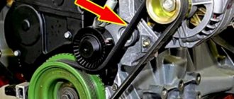
DIY belt replacement process
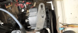
front part
Having gained access to the required element, inspect it. Replacing the alternator belt on a VAZ 2107, then watch the video on replacing the clutch on a VAZ 2107. If there is no visually visible damage on the belt, just check the tension, it may have weakened. Generator belt. Replacing the VAZ 2107 generator belt. Checking the tension of the VAZ 2107 generator belt To check the tension of the generator belt, you need to use a ruler to determine the amount of deflection in the area between the pump pulley and the crankshaft. This is easy to do, just press the belt with your fingers, simulating a pressure of approximately 10 kg, and by the distance of deflection you can determine whether the element is in acceptable tone. The maximum standards in a narrower place are 10-15 mm, and in those where the space between the pulleys is wider - 12-17 mm.
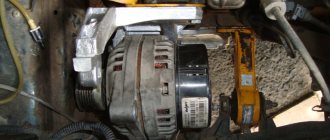
You only need to remove the belt from the pulleys if it is completely replaced; you do not need to do this to retighten it. At the bottom of the car, unscrew the nut securing the generator underneath by one turn. In the engine compartment, loosen the upper fastening nut of the same device a few turns. Under no circumstances should you completely unscrew the fasteners, just loosen them until they begin to turn freely.
To remove the belt, you will need to press the alternator slightly against the engine, but under no circumstances do this with your bare hands. Replacing the rear brake discs of a Ford Focus 2 video, removing and replacing the front and rear brake discs of a Ford Focus, how to change the rear struts on a VAZ 2112 with your own hands, video, fuse. Then remove the belt. You need to start with the top pulley, and then with the rest. Only in this order will it be easy to remove the element. On injection car models, you will also need to remove the crankshaft position sensor, otherwise it will interfere with the removal of the belt.
After the manipulations have been completed, check the belt tension again using the previously described method.
To put on a new belt, you need to know some of the nuances of this process. For example, one of the most important points: you need to put the belt on, starting with the crankshaft pulley, then on the generator pulley, and only finally on the pump pulley.
Thanks to the video instructions, you can learn in more detail and clearly how to change or tighten the alternator belt if you plan to do it yourself for the first time.
Malfunctions
The first symptom of a generator malfunction is the appearance of the following errors on the on-board panel:
- P0560 indicates insufficient electrical voltage in the circuit. Direct notification of insufficient current from the generator. The first reason may be: weakening of the transmission belt, poor contact at the generator terminals.
- P0561 is a low circuit voltage alert. In addition, the battery charge indicator lamp lights up during operation of the power unit. Accurately indicates a problem with the generator itself.
- P0562 indicates that the electrical voltage in the circuit is too high. The reason lies in the relay regulator. The device did not include high current protection at the generator output.
The appearance of errors requires the owner to check the generator for faults. They may be the following:
- Very low tension on the belt that transmits rotation from the power unit.
- Belt slipping on the generator or engine pulley. May cause wear on pulley surfaces.
- Break, short circuit and complete burnout of the excitation coil.
- Insufficient brush contact.
- Incorrect operation of the charge relay.
- Failure of the diode bridge.
- There is a short circuit in the circuit.
- Poor contact.
To accurately identify the cause of the malfunction, it is necessary to check each element of the circuit and the charge supply device to the battery one by one.
Repair and overhaul of generator VAZ-2107 37.3701
In this material we will talk about how to repair and overhaul the VAZ-2107 generator brand 37.3701. This manual is suitable for almost all classic generators, G-222 and others. The principles of assembly and disassembly are the same for everyone. The main thing during such work is to stock up on high-quality spare parts, because the most difficult and time-consuming thing here is the work process itself, and therefore it will be a shame to go through and disassemble the generator again because in a month the bearing will make noise or the diode bridge will burn out again. Ideally, we will need a universal puller (I personally used a rod puller instead, which turned out to be not very convenient, but after some fiddling around I removed the bearing with it, you can do without it). It is also good to have a metal brush or brushes in the form of attachments for a drill on hand. Anyway, let's go...
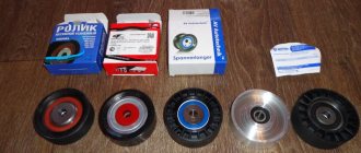
If there is a problem with the bearings or the belt is dirty
If the device slipping in the VAZ-2107 is caused by the slow rotation of the pulley, which depends on the serviceability of the bearings, it’s time to start repairing the latter. To do this, you will again need to use the instructions on how to remove the generator and how to disassemble it. If you are not confident in your abilities, you should not experiment; it is better to contact a service station.
Another possible breakdown is contamination on the belt. It is difficult to completely clean the part from dirt and dust, so experts recommend replacing the old belt with a new one.
Step-by-step video instructions on how to properly disassemble the VAZ-2107 generator are shown below:
One of the reasons why the battery is not charging is a breakdown of the generator. Before you independently repair the VAZ 2107 generator, you need to find out the causes of the breakdown and become familiar with the technology for removing, restoring and installing it.
- Causes of generator malfunction
- Removing the VAZ 2107 generator
- Disassembling the VAZ 2107 generator
- Assembling a VAZ 2107 generator
VAZ 2105 – disassembly and repair of generator 372.3701
03 October 2013
Disassembly of the generator series 372.3701 on a VAZ 2105 car is carried out for repairs in order to replace failed elements. Prepare a standard set of tools; you will also need a three-beam bearing puller and a metal mandrel for pressing in new bearings. If you have everything you need, follow the steps below:
- First of all, you need to remove the impeller from the pulley. To do this, we keep the rotor from turning by placing a screwdriver between the impeller blades and resting it against the generator housing like a lever.
- We unscrew the impeller fastening nut, remove it and the limit washers located under it and the segment key on the shaft.
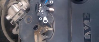
- Now you need to remove the voltage regulator. We disconnect the block with the power wires from it.
- Then use a Phillips screwdriver to unscrew the two screws securing it to the generator housing.
- We take the regulator out of its seat and put it aside so that it does not interfere.
- Now you need to remove the generator cover. To do this, use a ten-point socket to unscrew the four nuts securing the covers and remove the bolts.
- We rest the cover against a wooden block, after which we apply light blows to the end of the shaft with a rubber hammer or a regular one (through a wooden spacer), thereby pressing the front cover bearing off it, which also remains in place.
- Remove the cover and the spacer located underneath it.
- If necessary, we replace the cover bearing. To do this, use an eight-mm socket to unscrew and remove the four screws securing its cover.
- After that, we press out the bearing using a mandrel of suitable diameter.
- We remove the rotor. We turn the generator over with the back cover facing up and install it on wooden spacers.
- We take a small tube made of soft metal and through the hole where the voltage regulator was installed, we apply light blows to the rotor.
- If it is necessary to replace the rotor bearing, we use a three-beam puller.
- Now you need to remove the stator winding from the generator housing. To do this, from the inside, use an eight-point socket wrench to unscrew the nuts securing the rectifier unit, which are also fastenings for the terminals of the stator windings.
- We remove two bolts and remove the stator from the housing.
- Using a ten-point deep socket, unscrew the output nut “30” and, having removed it, remove the insulating gasket located under it.
- Then remove the rectifier unit from the housing.
- Unscrew the fastening screw and remove the capacitor.
↑ How to assemble a generator
The misalignment of the holes in the legs of the generator covers should be no more than 0.4 mm. Therefore, during assembly it is necessary to insert a special gauge into these holes. It is a stepped cylindrical mandrel having a diameter of 12 mm on one side and 22 mm on the other.
The conical spring washer of the pulley with its convex side should be in contact with the nut. Tighten the pulley nut to a torque of 38.4–88 N·m (3.9–9.0 kgf·m).
When assembling a generator 37.3701 manufactured before 1996 (with a dismountable regulator-brush holder assembly), in order to avoid breakage of the brushes, before installing the regulator with the brush holder in place, it is necessary not to completely insert the brush holder into the regulator, but only partially push it in and insert it into the generator in this form. After installing the brush holder in place in the generator cover, lightly press the adjuster and slide it into the generator.
Disassembling the generator VAZ 2107, VAZ 2105, VAZ 2104
generator, replacement and troubleshooting
Generator 37.3701. Clean and blow out the generator with compressed air. Lock the generator pulley with the clamp included in the set of tool 67.7823.9504, unscrew the pulley fastening nut and compress the pulley using a puller. Remove the key and tapered washer from the pulley. Tool kit 67.7823.9504 includes a regular puller and grip. The latter consists of two steel half-rings that are inserted into the pulley groove. The half rings have the same cross-section as the generator drive belt. On one side they are hinged, and on the other they are equipped with levers that are compressed with one hand when removing the pulley.
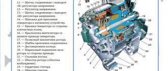
Parts of the VAZ 2107 generator - 37.3701: 1 - voltage regulator assembled with brush holder for generators produced since 1996; 2 - voltage regulator and brush holder for generators manufactured before 1996; 3 — terminal block for additional diodes; 4 — insulating bushings; 5 - rectifier block; 6 — contact bolt; 7 - stator; 8 - rotor; 9 — spacer sleeve; 10—inner bearing mounting washer; 11 — cover from the drive side; 12 - pulley; 13 - outer bearing mounting washer; 14 - coupling bolt; 15 — front rotor ball bearing; 16 — bushing; 17 — cover from the side of the slip rings; 18 — buffer sleeve; 19 — clamping sleeve; 20 - capacitor
Disconnect the wire from plug “B” of the voltage regulator. Disconnect the wires of the regulator and capacitor from terminal “30” of the VAZ 2104, VAZ 2105, VAZ 2107 generator and unscrew the screws securing the voltage regulator. For generators made before 1996, in order not to break the brushes when removing the brush holder, insert the blade of a screwdriver between the body of the regulator 2 and the brush holder and partially pull the regulator out of the generator, leaving the brush holder of the VAZ 2105 generator in place. After this, tilt and remove the regulator together with the brush holder from generator Remove the capacitor 20 by unscrewing the fastening screw. Unscrew the nuts of the coupling bolts 14 and remove the generator cover 11 and the rotor 8. Unscrew the nuts of the bolts connecting the tips of the diodes to the stator winding terminals and remove the stator 7 from the generator cover 17. Unscrew the nut of the contact bolt 6, disconnect from pads 3 plug wires of additional diodes and remove the rectifier unit 5.
Removing the winding (stator)
To do this, you need to unscrew the three nuts from the inside with a head, as shown in the picture:
And after this, the stator can be removed without any problems, since it is disconnected from the diode bridge:
If it needs to be replaced and you need to remove it completely, then of course you will need to disconnect the plug with the wiring, which is visible in the top photo.
What generators can be installed on the “seven”
The design of the VAZ 2107 allows the installation of not only the G-221A generator. Therefore, if necessary, the driver can install a more efficient device, but in this case some changes will have to be made to the electrical circuit of the car. The question arises: why should a motorcyclist even change his “original” generator?
The G-221A was the optimal device for equipping cars at the beginning of mass production. However, a lot of time has passed since the 1980s, and today almost every motorist uses modern electronic devices:
- sound systems;
- navigation systems;
- additional lighting devices (tuning), etc.
Accordingly, the G-221A generator cannot cope with heavy loads, so drivers begin to look for more powerful units.
At least three more powerful units can be installed on the “seven”:
- G-222 (generator from Lada Niva);
- G-2108 (generator “eight”);
- G-2107-3701010 (Car injection model with carburetor).
It is important that the last two models do not require changes in the design of either the generator housing or its mountings. If you are installing a Niva generator, you will have to make some changes.
Video: principle of operation of the generator
Connection diagram G-221A
As an electronic device, the generator must be used correctly. Accordingly, its connection diagram should not cause misunderstandings. It is worth noting that the “seven” drivers can easily connect all the generator terminals on their own, because the circuit is accessible and understandable to everyone.
Many car owners wonder where to connect which wire when replacing the generator. The fact is that the device has several connectors and wires, and when replacing it is easy to forget which wire goes where:
- The orange one is useless for wiring, you can leave it as is or connect it directly to the gray one to start automatically;
- a thick gray wire goes to the brushes from the voltage regulator;
- the gray thin wire goes to the relay;
- yellow wire - coordinate indicator lamp on the control panel.
Completion
The most typical and common breakdowns were presented. For correct diagnosis in serious cases, special stands are needed, which are present in many workshops. It should be noted that sometimes the cost of such repairs can be equal to or even exceed the price of a new generator. Therefore, repair is not always the answer.
From the text it becomes clear that there are no significant differences between the injection VAZ 2107 and the earlier carburetor version. The same applies to the modification of the VAZ 21074 and all others.
Generator manufacturers claim that the generator is designed for 200-250 thousand kilometers. After passing the barrier of 100-150 thousand, it is necessary to conduct a thorough inspection and lubricate all mechanical connections.