For the first time, the Russian auto industry installed electric power steering on Kalina. At the first stages, it worked extremely unstably, up to a complete shutdown. Later, they tried to eliminate the shortcomings, but the EUR remained a weak link and periodically fails, as evidenced by the exclamation mark on the panel. This is evidenced by the feeling of a heavy steering wheel, and turning with one hand becomes difficult.
The principle of operation of the electric booster is to reduce the force that needs to be applied when turning the steering wheel. The Kalina electric power steering control unit uses sensors to calculate the operation of the electric motor at the current speed and torque. Thereby giving a signal of the effort with which the driver needs to be helped when turning. After all, it does not work constantly and needs adjustment, which is carried out by the block.
Reasons for shutdown
The main reason lies in the electric power steering. When ignited, the system performs a self-diagnosis and if the mechanism does not pass it, a signal is turned on indicating a malfunction. The color of the signal indicates the degree of danger. The light turns red, the problem needs to be fixed urgently. If the color is yellow, the vehicle can be operated, but safety precautions should be taken. There may be several reasons why the electric power steering on Kalina does not work:
- speed sensor malfunction;
- torque sensor malfunction;
- speed exceeds 60 km/h;
- engine speed is less than 400 per minute;
- failure in the control unit;
- poorly soldered contacts;
- insufficient tension.
Software shutdown
- The electric power steering on Kalina turns off after 60 km/h. Therefore, keep this point in mind; it is set in the system unit and is not a breakdown. The Priora's electric power steering is switched off at a speed of 110 km/h.
- Also, the EUR does not work at low engine speeds. If the value is less than 400 rpm, it is not active.
This is software planned inactivity. It is needed to give information to the steering wheel at high speed and reduce wear of the mechanism.
Electrical booster malfunctions
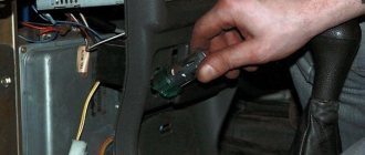
In the event that it is impossible to immediately check the cause of failure of the electric power steering on Kalina, you need to remove the fuse from the block.
This is necessary to prevent sudden activation of the mechanism, which leads to emergency situations. A direct indicator of a malfunction of the speed sensor in Kalina's electric power steering is a non-working speedometer, as well as a lit-up exclamation mark on the dashboard. It may not work for several reasons. Check the appearance of the sensor; if it is covered with dirt, simply clean it. See if any metal shavings have become magnetized and remove those as well.
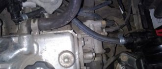
If this does not help, then the sensor is probably faulty. Such sensors are now inexpensive and can be found in many auto parts stores. We do the same for the torque sensor. But where is the speed sensor? It is usually located in the gearbox housing, see photo on the left.
Another cause of malfunction of Kalina’s electric power steering is the generator. The control unit requires a voltage of 13.6 V to operate; if you have less, change the voltage regulator (chocolate) on it.
Also, the contacts could simply become disconnected due to poor-quality soldering. You can either disassemble and solder the contacts or send it to service.
If the problem is in the control unit, it is difficult to solve this problem yourself; the service will either solder it or you will have to buy a new one.
How to determine the malfunction?
Despite the fact that repairing the EUR requires contacting a car service, you can detect the first symptoms of a malfunction yourself
.
Viburnums on the front panel have a special yellow indicator, which, in the event of a breakdown of the electric amplifier, lights up and reports an error in the system. If it lights up, it means you have another reason to visit the nearest auto repair shop. But it’s immediately worth noting that the yellow indicator does not indicate a critical malfunction, but only signals the occurrence of a problem that allows you to drive the car, but without the participation of the ESD.
If the electric power steering has completely failed, it is better to stop immediately and pull out its fuses.
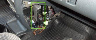
. In Kalina they are located on the left side of the steering wheel. Theoretically, in case of malfunctions, the EUR should turn off on its own. However, it doesn’t happen once at a time. Therefore, to be sure, it is still worth taking care of the fuses.
Fuse box
The weak link of the electric power steering on Kalina is the fuse box; if something doesn’t work, it’s worth checking them.
To get to them, you need to open the dashboard, to the left of the steering wheel. To do this, pull the top part towards you and the latch will open. Check if the fuse is working, if it fails, replace it. It is very easy to check, check the integrity of the thread inside the fuse. Changing a 50 amp relay to a 30 amp one will also help.
Newer versions of Kalina are equipped with electric amplifiers from Hyundai, which has a positive effect on its reliability. However, there are still thousands of cars with the domestic version, which malfunctions and breaks down from time to time. Now it will be easier for you to repair the electric power steering on Kalina yourself. The main thing to remember is that not every amplifier shutdown is a breakdown. And you can find the problem yourself and fix it, but somewhere you will have to go to a service center.
The need to replace the electric power steering and the importance of a qualified approach
Replacing the electric power steering should only be done by experienced craftsmen, and if the warranty period for the Lada Kalina has not yet expired, then the best solution would be to contact the dealer network to solve the problem. If the warranty has expired, and it is difficult to collect additional material resources for qualified repair of the device, then the way out of this situation is to install the electric power steering yourself.
It should be taken into account that this procedure is quite complicated. Therefore, it is not worth carrying out without certain training and technical skills. The result of unskilled actions can be not only a complete failure of the system, but also more complex and expensive repairs. Therefore, the installation of the EUR should be done only after studying all the details and features of the vehicle’s networks.
In such a situation, the device connection diagram will become an indispensable assistant and will allow you to perform the necessary actions more clearly.
To remove a faulty electric booster, it is necessary to partially disassemble the panel located under the steering wheel and disconnect all the wires going to the device. Installing a new type of electric power steering may not be necessary, since the likelihood is quite high that after carrying out some preventive measures, the old device will work no worse than the new one.
One of the most common problems of this type is a knocking sound in the electric power steering, accompanied by a squeaking sound when the wheel itself is turned. In such a situation, EUR lubricant can solve the problem. If this step does not help, then the device requires more detailed diagnostics or complete replacement.
Installing the EUR requires some care. All wires must be connected, the device itself must be installed in its proper place, and the steering column panel must be reassembled.
Electric power steering on Kalina
Latest model of Kalina
Lada Kalina cars are equipped with electric power steering. Its design is very simple, it consists of one block, so even on a standard vehicle, the EUR can be installed without any problems. It contains no liquid, which means it is easy to maintain. But it is worth paying attention to the experience of foreign manufacturers who try not to install ESD in their cars. This mechanism has a special feature: it can operate at both low and high speeds. The second option is undesirable, since the slightest movement of the steering wheel can cause the car to drift into a ditch or to the side of the road.
The Lada electric power steering circuit provides for the mechanism to operate at different speeds, and when driving it either functions or turns off. The malfunction is that the EUR stops in one state. It is prohibited to use the vehicle until the breakdown is repaired. A yellow light on the dashboard will indicate the problem. It shows an exclamation mark and a steering wheel. If the malfunction lies in the power steering unit, and it is not possible to eliminate it, you should remove the fuse that is responsible for the operation of the electric amplifier. It should be taken into account that EMUR can fail not only on old, but also on new Kalinas that have not had time to be run-in.
Causes of EUR failure
One of the main reasons why the electric power steering on Kalina may turn off is a breakdown of the device itself. When the ignition is turned on, the system automatically performs diagnostics, which subsequently fails. As a result, the electric power steering does not work due to its own shutdown, which undoubtedly negatively affects the comfort when driving the car.
Repairing the electric power steering can be quite expensive, so if the Kalina is still under warranty, it makes sense to have your power steering repaired at the dealer. In the event that the system has completely failed, you must first turn off the power. In this case, the engine torque will be received by the steering element (rack), bypassing the amplifier.
Another reason why the electric booster does not work is the failure of the speed sensor, which is responsible for the operation of the system in various driving modes. The power steering operates at full power only when driving at minimum speed. When the vehicle accelerates, the force that the system creates on the rack decreases, and this is what the speed controller is responsible for. Do-it-yourself EUR repair involves replacing the sensor yourself; the cost of such an element today is not high.
If a speed sensor directly connected to the speedometer breaks down, then the unit that controls the power steering receives incorrect data. The system automatically turns off, at this moment a diode indicator appears on the control panel, which informs the driver about a malfunction of the device. To avoid the need to repair the amplifier, it is enough to carry out diagnostics in time with a paper clip. Thanks to diagnostics, the motorist will be able to find out about all the problems that are present in various mechanisms and transport components.
Let's summarize this point - for what reasons does the electric amplifier refuse to work:
- There is no signal from the speed sensor. The problem may be either a regulator failure or a wiring fault.
- Very low voltage level in the car wiring. It is necessary to measure the voltage and solve the problem.
- The permissible engine speed has been exceeded.
- The control unit has failed. Repair will solve the problem, but usually if the unit breaks down, it has to be replaced.
Detailed electrical diagrams of car components
Instrument panel wiring harness wiring diagram
1,2,3,4 blocks of the instrument panel wiring harness to the rear wiring harness blocks; 5,6 blocks of the instrument panel wiring harness to the blocks of the front wiring harness; 7 block of the instrument panel wiring harness to the block of the wiring harness of the air supply box; 8 block of the instrument panel wiring harness to the block of the front wiring harness; 9 lighting control module; 10 ignition switch; 11 on-board computer mode switch; 12 windshield wiper switch; 13 horn switch; 14 light signaling switch; 15 instrument cluster; 16 evaporator temperature sensor; 17 interior air temperature sensor; 18 air conditioner switch; 19 controller of the automatic climate control system; 20 heater damper gearmotor; 21 rear window heating switches; 22 alarm switch; 23 brake signal switch; 24 cigarette lighter; 25 electric power steering control unit; 26,27 connectors for the instrument panel wiring harness to the radio; 28 backlight lamp for the heater control panel; 29 lighting Lada Kalina; 30 mounting block: K3 additional starter relay; K4 additional relay; K5 relay breaker for direction indicators and hazard warning lights; K6 wiper relay; K7 relay for high beam headlights; K8 horn relay; K9 relay for turning on fog lights; K10 relay for turning on the heated rear window; K11 electric seat heating relay; K12 air conditioning compressor clutch activation relay; 31 heater motor switch; 32 electric heater motor; 33 additional resistance of the heater electric motor; 34 glove box lighting; 35 glove box lighting switch; 36 control unit of the automobile anti-theft system APS6; 37 driver airbag module; 38 passenger airbag module; 39,40 the instrument panel wiring harness blocks to the ignition system wiring harness blocks.
Electrical connection diagram for the wiring harness of the ignition system Lada Kalina 11174, 11184, 11194
1 oil pressure warning light sensor; 2 coolant temperature indicator sensor; 3 additional fuse box; 4 fuses for the electric fan of the engine cooling system; 5 electric fuel pump relays; 6 relays for the electric fan of the engine cooling system; 7 ignition relay; 8 relays 2 of the electric fan of the engine cooling system; 9 relay 3 of the electric fan of the engine cooling system; 10 electric fan of the engine cooling system; 11 throttle position sensor; 12 idle speed controller; 13 coolant temperature sensor; 14 diagnostic block; 15 ignition system harness block to the instrument panel harness block; 16 solenoid valve for purge the adsorber; 17 speed sensor; 18 ignition system harness block to instrument panel harness block 2; 19 mass air flow sensor; 20 crankshaft position sensor; 21 oxygen sensors; 22 controller; 23 rough road sensor; 24 diagnostic oxygen sensor; 25 ignition coil harness block to the ignition system harness block; 26 ignition coils; 27 ignition system harness block to ignition coil harness block; 28 spark plugs; 29 nozzles; 30 resistor; 31 air conditioning pressure sensors; 32 blocks of the ignition system harness and injector wiring harness; 33 phase sensor; 34 knock sensor.
Electrical connection diagram of the front VAZ-11184 wiring harness
1 headlight right; 2 right fog lamp; 3 speed sensor right front; 4 speed sensor left front; 5 air temperature sensor; 6 VAZ starter; 7 rechargeable battery; 8 generator; 9 blocks of the battery and starter harness and the front harness; 10 ABS hydraulic unit; 11 reverse light switch; 12 reverse lock; 13, 14, 15, 16 blocks of the front wiring harness to the blocks of the instrument panel wiring harness; 17 front wiring harness block to rear wiring harness block; 18 left headlight 11184; 19 left fog lamp; 20 electric washer motor; 21 beeps; 22 air conditioning compressor; 23 air conditioning fan electric motor.
Electrical connection diagram for rear wiring harness VAZ-11184
1 – 4 blocks of the rear wiring harness to the blocks of the instrument panel wiring harness; 5 rear wiring harness block to front wiring harness block; 6 side direction indicator, right; 7 left side direction indicator; 8 handbrake sensor; 9 blocks of the rear wiring harness to the rear right loudspeaker; 10 interior lamp; 11 reverse lock switch; 12 trunk light; 13 additional brake signal; 14 electric fuel pump module; 15 right lamp; 16 blocks of the rear wiring harness to the rear left loudspeaker; 17 rear window heating element; 18 rear wiring harness block to additional wiring harness block 3 (trunk lid); 19 rear wiring harness block to additional wiring harness block 2 (left rear door); 20 block of the rear wiring harness to the block of the additional wiring harness (right rear door); 21 left lamp 11184; 22 electrical package controller; 23 block of the rear wiring harness to the block of the rear additional wiring harness (left front door); 24 rear wiring harness block to rear additional wiring harness block 2 (right front door); 25 airbag control unit; 26 driver's seat belt pretensioner; 27 passenger seat belt pretensioner; 28 interior air temperature sensor; 29 right rear speed sensor; 30 left rear speed sensor; 31 electric heater for the right seat; 32 right seat electric heater switch; 33 left seat electric heater switch; 34 electric heater of the left seat.
Useful: Lada X-Ray diagram (Lada XRAY)
Diagram of electrical connections of the additional rear wiring harness (tailgate wiring harness) and the wiring harness of the license plate lights of the LADA KALINA 11174 car.
1 rear window wiper motor; 2 additional brake signal; 3, 4 blocks of the rear wiring harness, additional to the blocks of the rear wiring harness; 5 block to the trunk lock electric motor; 6 trunk lock; 7 rear window heating element; 8 block of the rear wiring harness, additional to the block of the wiring harness of the license plate lights; 9 block of the wiring harness for the license plate lights to the block of the rear additional wiring harness; 10, 11 license plate lights.
Electrical connection diagram for rear wiring harness VAZ-11174
1 – 4 blocks of the rear wiring harness to the blocks of the instrument panel wiring harness; 5 rear wiring harness block to front wiring harness block; 6 side direction indicator, right; 7 left side direction indicator; 8 handbrake sensor; 9 blocks of the rear wiring harness to the rear right loudspeaker; 10 interior lamp; 11 reverse lock switch; 12 trunk light; 13 block of the rear wiring harness to the block of the additional wiring harness; 14 electric fuel pump module; 15 right lamp VAZ-1174; 16 blocks of the rear wiring harness to the rear left loudspeaker; 17 rear wiring harness block to additional wiring harness block 3; 18 rear wiring harness block to additional wiring harness block 2 (left rear door); 19 block of the rear wiring harness to the block of the additional wiring harness (right rear door); 20 left lamp; 21 electrical package controllers; 22 block of the rear wiring harness to the block of the rear additional wiring harness (left front door); 23 rear wiring harness block to rear additional wiring harness block 2 (right front door); 24 airbag control unit; 25 driver's seat belt pretensioner; 26 passenger seat belt pretensioner; 27 interior air temperature sensor; 28 right rear speed sensor; 29 left rear speed sensor 1174; 30 electric heater of the right seat; 31 right seat electric heater switch; 32 left seat electric heater switch; 33 electric heater of the left seat.
Electrical connection diagram of the front VAZ-11174 wiring harness
1 headlight right; 2 right fog lamp; 3 speed sensor right front; 4 speed sensor left front; 5 air temperature sensor; 6 starter VAZ-1174; 7 rechargeable battery; 8 generator; 9 blocks of the battery and starter harness and the front harness; 10 ABS hydraulic unit; 11 reverse light switch; 12 reverse lock; 13, 14, 15, 16 blocks of the front wiring harness to the blocks of the instrument panel wiring harness; 17 front wiring harness block to rear wiring harness block; 18 left headlight Lada Kalina; 19 left fog lamp; 20 electric washer motor; 21 beeps; 22 compressor; 23 air conditioning fan electric motor; 24 rear window washer motor.
Electrical connection diagram for rear wiring harness VAZ-11194
1 – 4 blocks of the rear wiring harness to the blocks of the instrument panel wiring harness; 5 rear wiring harness block to front wiring harness block; 6 side direction indicator, right; 7 left side direction indicator; 8 hand brake sensor Lada Kalina; 9 block of the rear wiring harness to the block of the additional wiring harness; 10 interior lamp; 11 reverse lock switch; 12 trunk light; 13 electric fuel pump module; 14 right lamp VAZ; 15 rear wiring harness block to additional wiring harness block 3 (trunk lid); 16 rear wiring harness block to additional wiring harness block 2 (left rear door); 17 block of the rear wiring harness to the block of the additional wiring harness (right rear door); 18 left lamp 1194; 19 electrical package controller; 20 block of the rear wiring harness to the block of the rear additional wiring harness (left front door); 21 rear wiring harness block to rear additional wiring harness block 2 (right front door); 22 airbag control unit; 23 driver's seat belt pretensioner; 24 passenger seat belt pretensioner; 25 interior air temperature sensor; 26 speed sensor right rear; 27 left rear speed sensor; 28 electric heater of the right seat; 29 right seat electric heater switch; 30 left seat electric heater switch; 31 left seat electric heater.
Wiring diagram for fog lights
1 - fuse in the assembly block; 2 — immobilizer output; 4 — rear fog lights; 4— external optics control unit; 5 — ignition switch; A - to power supplies.
Removing the electric amplifier
- If you decide to repair the electric power steering, then first of all you need to dismantle the steering column switches. Next, you need to disconnect all the blocks with wires from the control panel - if you need to remove the ignition switch, then to do this you need to unscrew three self-tapping screws. A Phillips screwdriver is used for this.
- After completing these steps, you can dismantle the lower cross member of the control panel. To do this, press the clips that secure the wire block, and then disconnect them from the system control unit. Only after these steps can you disconnect the block from the switches themselves.
- The bracket itself is fixed with several nuts, they are unscrewed.
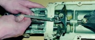
- The entire steering column must be carefully lowered. You need to find the screw that secures the cardan to the assembly shaft. This screw is unscrewed, while you need to hold the nut to prevent it from turning. After dismantling the screw, the terminal clamp must be released, then the intermediate shaft is carefully removed. To prevent installation problems, the location of the shaft, as well as gears, must be marked with a marker. If the marks on the shafts are not aligned, this will lead to problems with the system. When removing the electric amplifier, do not damage the wiring under any circumstances.
- As for installation, the procedure is carried out in reverse order (the author of the video is Murzik Bely).
Characteristics of ESD malfunctions and the need for subsequent diagnostics
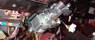
The design of the EUR is quite simple, which makes its repair quite simple. But its location was not chosen very well by the manufacturer. The electric amplifier module is mounted directly under the heater radiator. Therefore, during the operation of the device, especially in winter, it is periodically exposed to temperature. Which is one of the reasons for its failure.
Unfortunately, this development of events occurs quite often. Failure to operate the ESD is associated with some difficulties in driving and the appearance of certain problems. In most cases, the following factors are responsible for malfunctions:
- lack of speed sensor signal;
- low voltage in the vehicle's power supply network;
- the maximum system speed has been exceeded;
- The control unit is faulty.
All these factors lead to device failure. Diagnosis of a similar condition is carried out by the car itself as a result of starting the system and turning on the on-board computer, which checks the serviceability of all systems. If there is no signal from any element, the computer automatically considers it faulty, and displays the corresponding information on the dashboard.
If the electric power steering does not work, a special orange light appears on the screen, shaped like a steering wheel with an exclamation mark. The manufacturer's instructions state that failure of the ESD requires urgent repairs. Why should the driver move at low speed to the service station to carry out the appropriate actions. In practice, things are a little different.
In most cases, a light on the dashboard does not mean repair. It indicates the presence of any problem in the EUR units. This can be either a malfunction in the power circuits, which is implied by the device’s connection diagram, or a failure of one of the sensors. At the same time, this fact has absolutely no impact on the control of the vehicle.
The real problem is problems that affect the sensitivity of the steering wheel and prevent it from working properly. These problems arise quite often and require immediate response, since ignoring them can lead to dire consequences. To quickly neutralize this problem, you should remove the fuse, which is located on the left side of the steering wheel.
This step will allow you to get to the repair site without interference, although driving the car will become a little more difficult.
A faulty EUR will not affect the steering wheel and interfere with driving the car.
Causes of EUR failure
Why does the electric power steering on the Lada Kalina not work, turns off and refuses to work, what are the signs of a steering wheel with power steering knocking, jamming, biting or squeaking? To repair the system yourself, you need to know how diagnostics are carried out and what causes precede the breakdown. Most often, the failure of the amplifier is caused by a breakdown of the unit itself and the amplifier fails. Problems of this type are resolved by thoroughly checking the system to identify the exact problem.
As practice shows, often the inoperability of the electric amplifier (failure) is associated with a breakdown of the speed controller.
- the steering wheel is jammed,
- jams
- becomes tight
- and others
Because the speed controller sensor ensures activation and deactivation of the electric power steering under different driving modes. The amplifier on Kalina works if the car is moving at low speed. When the speed begins to increase, the booster automatically turns off, allowing for safer machine control when driving at high speeds.
So, briefly about the reasons for the inoperability of the EUR:
- The speed controller has failed or the control unit does not receive or disappears a signal from it. In this case, the reason may lie in either a breakdown of the sensor, damaged wiring, or poor contact of the controller with the on-board network.
- The voltage in the vehicle's electrical network has decreased. The reasons can be different, ranging from a dead battery and an inoperative generator to the use of inappropriate electrical equipment in the car.
- The permissible crankshaft speed has been exceeded.
- Incorrect operation or failure of the control module. Depending on the cause, the control unit may need to be repaired; more detailed diagnostics need to be done.
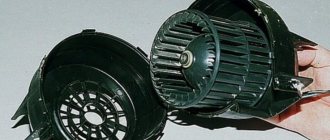
Components of the Lada Kalina electric power steering and its operation
The electric power steering for Kalina is a special device that is connected to the steering wheel systems and ensures smooth and soft operation. This solution allows you to rotate the steering wheel without much effort.
The design of the EUR itself is quite simple and consists of only a few parts:
- electric motor;
- gearbox;
- Control block;
- torque sensor;
- speed sensor;
- crankshaft speed sensor.
The EUR is a fairly simple system. But even such a design allows the device to receive all the necessary information to ensure the movement of the machine. The operation of the device is controlled directly by the on-board computer, which is included in the factory equipment of the Lada Kalina. The electric power steering is activated when the rotation speed reaches 400 rpm, and is turned off when the speed exceeds 60 km/h.
Such frames provide the best performance and allow you to drive the car in the very period that is most difficult. In addition, such indicators are determined by the manufacturer based on safety considerations, since operating the ESD at high speeds is associated with a certain risk.
As mentioned above, connecting the device makes the steering wheel extremely sensitive, which can become a big problem at high speeds. That is why, when exceeding 60 km/h, the amplifier is switched off by the system, making it more static and safer.
Diagnostics
To check the amplifier in a car, you need to remove the plastic trim on the steering column; to do this, unscrew the bolts securing it from the bottom.
Then you will need to get to the 8-pin plug, its pinout is as follows:
- The blue contact is connected to the ignition switch, this is 12 volt power;
- the red-brown contact is the connection cable to the tachometer;
- the gray contact goes to the car speed controller;
- white and pink wire - amplifier control indicator;
- black-yellow contact is a diagnostic line;
- the next contact is empty, the wire is not connected to it;
- brown contact is ground;
- empty.
More accurate results will be obtained by checking the amplifier using a scanner. But since such equipment can usually only be found at service stations, you can try to check the operation of the system with a paper clip.
To check you need to do the following:
- First the ignition is turned off.
- Then, using a paper clip, you need to close contacts numbered 6 and 7 of this plug, while the plug itself does not need to be removed.
- Next, the ignition must be turned on.
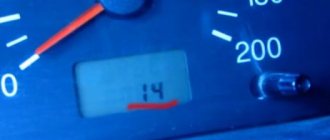
- After completing these steps, the EUR failure indicator located in the dashboard will begin to blink; by the number of blinks, you can determine whether the system is broken (the author of the video is Gosha Vakhromeev).
How to understand where to look for the cause by the blinking indicator icons:
- one long signal and one short signal - the electric amplifier is working;
- one long and two short - no engine speed signal;
- one long and three short - the torque controller is out of order or there is no power supply;
- one long and four short blinks—problems in the operation of the electric power steering motor;
- one long and five short - the steering shaft position controller has failed;
- one long and six short - the motor rotor position controller has failed;
- one long and seven short - problems with the electrical network - the voltage is either too high or very low;
- one long and eight short - the control module of the electric amplifier has failed;
- one long and nine short - the speed controller is broken.
General diagram of VAZ-1117, VAZ-1118, VAZ-1119
1 – right headlight; 2 – engine compartment lamp switch; 3 – sound signal, 4 – Lada Kalina starter; 5 – battery; 6 – generator; 7 – windshield wiper electric motor; 8 – left headlight; 9 – power window switch of the right front door (passenger]; 10 – power window motor of the right front door; 11 – right front door lock; 12 – connection block to the right front column; 13 – windshield washer motor; 14 – air temperature sensor; 15 – connection block to the injection system wiring harness; 16 – left front door lock; 17 – brake fluid level sensor; 18 – connection block to the left front column; 19 – right front door power window switch (driver); 20 – left front door power window switch; 21 – door lock switch in the switch block; 22 – electric window motor of the right front door; 23 – mounting block; 24 – immobilizer; 25 – power accessories control unit; 26 – instrument cluster; 27 – right side turn signal; 28 – glove compartment lighting lamp ; 29 – glove compartment lamp switch; 30 – brake light switch; 31 – ignition switch; 32 – lighting control module; 33 – steering column switch; 34 – left side direction indicator; 35 – connection block to the right rear column; 36 – rear door lock; 37 – rear window heating switch; 38 – reverse lock switch; 39 – alarm switch; 40 – heater motor switch; 41 – additional resistor; 42 – heater electric motor; 43 – block is connected to the left rear column; 44 – electric fuel pump with fuel level sensor; 45 – reverse lamp switch; 46 – handbrake sensor; 47 – cigarette lighter; 48 – reverse lock; 49 – connection block to the radio device; 50 – backlight lamps for heater control levers; 51 – Kalina illuminator; 52 – control unit for electromechanical power steering; 53 – interior lighting unit; 54 – right rear light; 55 – trunk locking motor; 56 – switch in the trunk lock; 57 – license plate lights; 58 – additional brake signal; 59 – rear window heating element; 60 – trunk lighting; 61 – left rear light
Elements of the instrument panel harness connection diagram
1, 3, 4, 5 — blocks of the tidy wire bundle to the front harness; 2, 8 - the same for the rear “pigtail” of wires; 6, 7, 9, 10 - continuation of the direction to the assembly unit; 11 — power supply for the lighting control device; 12 — set of instruments; 13 — toggle switch for the electric motor of the stove; 14 — power supply to the air supply box; 15 — ignition switch Lada Kalina; 16 — immobilizer block; 17 — block of the dashboard wiring harness to the ignition system wire bundle; 18 — cigarette lighter power supply; 19 — alarm switch; 20 — rear window heating switch; 21 — brake light switch; 22 — alarm light breaker; 23 — adjustment of computer modes ; 24 — windshield wiper control; 25 — VAZ horn switch ; 26, 27 — heating and ventilation control lighting lamps; 28 — glove box lighting; 29 — power supply to the on/off button in the glove compartment; 30, 31 — pinout for the standard radio; 32 — power supply to the electric motor of the stove; 33 — heater resistor network; 34 - electric amplifier control unit.
Dismantling and disassembling the electric amplifier
Before removing the amplifier, you need to remove all the steering column switches. Remove the steering rack cover and dismantle the devices, remembering to disconnect the connectors from the power supply.
How to remove the EUR with your own hands:
- After removing the switches, you will need to dismantle the lower cross member of the dashboard. To do this, you need to press the fasteners that secure the connector with wires, and then disconnect the wiring from the control module. Once these steps are completed, you can disconnect the connector from the switches.
- The system bracket is secured with nuts; you will need to unscrew them with a wrench.
- After this, the steering rack will need to be carefully lowered down. To do this, you will need to find the bolt that secures the driveshaft to the booster shaft. This bolt must be unscrewed, but when unscrewing, you will need to fix the nut, this will prevent it from turning. When the bolt is removed, the fastening will need to be loosened, after which the intermediate shaft will be carefully removed. At this stage, we recommend marking the position of the shaft and gears; you can use a marker for this. This step is very important because doing it will prevent possible installation problems in the future. If the marks on the shafts do not match, this may cause problems with the amplifier. When dismantling, be careful not to damage the wiring, as this will also lead to the inoperability of the ESD.
- When the unit is dismantled, it will need to be disassembled and the failed elements replaced. Further editing is done in reverse order (the author of the video is Murzik Bely).
How can I lubricate and adjust the EUR?
How and with what to lubricate the amplifier?
Litol can be used as a lubricant; the procedure is performed as follows:
- First you need to remove the plastic casing; to do this, unscrew the bolts that secure it. To unscrew, use a Phillips head screwdriver. It is also advisable to remove the lower cross member of the instrument panel, located under the steering wheel.
- Next, unscrew the two bolts that secure the amplifier itself; for this you will need a 13mm wrench. After this, the column can be released down.
- Unscrew another bolt, after which you can do the actual lubrication.
- First, the steering wheel is turned to the left until it stops. The lubricant is poured into a 10 cc syringe, which needs to be sprayed into the hole formed. You need to throw out all 10 cubes.
- Then the steering wheel is turned to the right until it stops - the syringe is again directed into the hole, all the lubricant is sprayed out.
- After this, the steering wheel should be turned to the middle position and again sprinkled with lubricant into the hole.
- Next, the steering wheel must be turned in different directions until it stops several times. The lubrication operation is repeated again.
- Then all the components are assembled in reverse order.
How to tighten the electric power steering rack?
The appearance of a knocking sound in the operation of the electric power steering is associated with the need to tighten the steering rack.
How to do it right:
- First you need to disconnect the battery; to do this, disconnect the terminals from it. Unscrew the battery mount; to do this, you need to unscrew two more nuts located at the edges. After this, the battery is removed and put aside.
- Then you need to lift the plastic stand, there are four more screws under it, they can also be unscrewed.
- Having done this, it is necessary to move this stand forward until the platform is disconnected from the air filter housing retainer pad. After this, the trim can be moved back, this will provide freer access to the rail itself.
- At the next stage, you will need to crawl your hand under the rail. Directly below it, as shown in the photo, there is a rubberized cap; it will need to be removed, this will allow the key to access the adjusting nut.
- To perform adjustment work, you will need a special wrench to tighten the rack; without it, the adjustment procedure will not be possible. Using this wrench, you need to crawl under the car rail to install the tool in the required hole.
- When adjusting, be careful not to overtighten the rack. If its tightening is very strong, then when cornering the rack will bite, and this, in turn, may affect the safety of movement. The angle of adjustment is always different, it depends on how much the nut is loose, but usually when performing such work the nut is tightened by approximately 30 degrees. This should be enough to get everything right. After the adjustment is completed, it will be necessary to check that this task was performed correctly. That is, you will need to make sure that the steering wheel turns normally to any position all the way and there is no knocking. If the knock remains, then the adjustment continues.
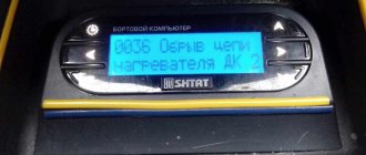
ESD error on the dashboard
The on-board computer will signal a malfunction of the EUR
Owners of a Kalina car with installed electric power steering enjoy pleasant and convenient control, but run the risk of encountering a problem - the “European Power Steering Error” light comes on. The reason for this may be either a complete failure of the system or its incorrect operation. It is worth noting that the sensor glows yellow, not red. This means that you can operate the car without a working Lada Kalina electric power steering, taking certain precautions.
You will have to apply more force to the steering wheel if you turn off the EMUR completely. This can be done quite simply by removing the fuse that supplies power to the control unit. If the power steering does not work or some strange phenomena are observed in its behavior, it is better to remove the fuse and undergo a complete diagnostic of the vehicle systems, which will show the cause of the breakdown. Driving without electric power assistance can be challenging. Out of habit, the steering wheel seems too tight, but in reality it is the same as on the Kalina “standard” configuration.
There are two reasons for EMUR failure: a malfunction of the speed sensor or a breakdown in the control unit. The first problem can be solved very quickly; this can be done even in a garage. In the second case, you will have to remove the control unit and contact an experienced electrician to install a new one. If the warranty is valid, you must show the car to specialists at a car service center.
If you still want to remove and install the control unit yourself, all you need is a Phillips screwdriver. First, all plastic panels under the steering wheel are dismantled to facilitate access to the unit. And do not forget that the battery should be disconnected, this will avoid problems with the electrical wiring. The plastic cover, which is located at the bottom of the panel, is secured with three bolts. They need to be unscrewed and the cover removed.
A view of the control unit itself opens after removing the cover. All plugs must be disconnected from the EMUR control unit. The block itself is secured with two bolts. Unscrew them and carefully pull the box down so as not to damage anything. Remember that the block is still attached to the plate. The box should be slightly higher than the pedals. Only after this do you need to unscrew the three bolts that secure the control unit to the plate. Now all that remains is to screw the new control unit onto the plate and carefully install everything in the reverse order. Secure the box with two bolts, then connect all the plugs, after which you can begin assembling the facing panels.
Fuse marking on a Lada station wagon
For this modification of the model, the same protective elements are provided. The fuse number for the cigarette lighter of the Lada Kalina station wagon is 20 or 18 depending on the generation. After installing a new element, it is recommended to follow some rules to extend the life of the device.
- Do not connect several powerful devices to the Lada Kalina at the same time (via a splitter). Otherwise the fuse will blow. The total power of the connected devices is calculated by the value (P=I*A, where I is the voltage of 12 volts, and A is the current). For the first generation this figure is 180 Watts, for the second – 240 Watts.
- Do not install a fuse with a higher amperage rating than that recommended by the manufacturer.
- Do not allow the socket to become loose or make poor contact with the cartridge - this can lead to a short circuit.
Video instruction
Sometimes a complete replacement of the device is required. To do this, you need spare parts and a standard screwdriver. The order of work is as follows.
- Open the hood, find the battery and remove the negative terminal from it.
- We unscrew the three mounting bolts around the parking brake handle, which is located on top of the central tunnel. We dismantle the hand brake limit switch.
- We unscrew the rear fastening screw, as well as additional screws on the sides.
- Remove the cover from the gear lever, and then lift the tunnel cover.
- We disconnect the power plug coming to the electrical wiring circuit.
- We press the special latches that hold the device itself. Once it pops out, you can replace it.
- Next, we install the new part on the Lada Kalina and carry out the reassembly process.
The video below will help you understand where it is located and how to replace the cigarette lighter fuse of the Lada Kalina model.
PROMOTION: SALE OF NEW CAR 2022 PRODUCTION
What a driver needs to know about EMUR
Electric power steering on Kalina serves to increase driver comfort. With its help, you can easily turn the steering wheel with one finger, even in a stationary car. This is convenient and practical, since parking with such a system turns out to be much easier and safer. The electric amplifier device includes:
- brushless electric motor;
- gearbox;
- Control block.
The electric motor is located under the steering wheel. A worm is installed on its shaft, which meshes with a plastic gear. The electronic unit controls the operation of the entire system using data that provides:
- torque sensor;
- speed sensor;
- crankshaft speed sensor.
After collecting data, the control unit regulates the supply voltage that is supplied to the electric motor. The lower the vehicle speed, the more voltage is supplied to the electric motor.
The lamp indicating a malfunction of the electric booster on Kalina lights up as soon as the ignition is turned on. After starting the engine it goes out. This is normal operation of the system, but if it breaks down, even after starting the engine, the lamp continues to light.
Reasons for failure of the electric amplifier.
- There is no signal from the speed sensor.
- Critically low voltage in the on-board network.
- The permissible engine speed has been exceeded.
- Control unit malfunction.
To repair the power steering, the steering wheel and part of the torpedo are removed
In the first three cases, failure of the EUR on Kalina can be eliminated quite simply. You need to either tighten the alternator belt or apply less force when pressing the accelerator pedal.
A malfunction of the control unit is a reason to visit a diagnostician who will conduct a quality inspection and identify the breakdown. Moreover, some problems can be fixed by an electrician, but some turn out to be fatal, and only replacing the entire unit will help.
There is a fifth reason for the EUR malfunction. Our negligence. I drove a car for five years (0-30,000 km) with the electric booster jamming (it would light up, then go out), of course it didn’t burn much, but finally it got to me. I removed the steering wheel trim and saw that it was not inserted all the way, i.e. until the main terminal of the EUR clicks. I already knew that everything would work. It's little things like these that give you a general idea of the car.
https://expertvaz.ru
Required tools: Phillips and flat-head screwdrivers, high head “13”. Disconnect the negative terminal of the battery and align the car's wheels straight ahead.
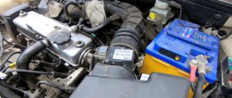
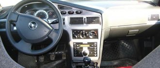
Engine control unit
This unit is located in the center console.
The fuses responsible for engine operation are located on top under the protective cover.
Photo - diagram
Designation
p, blockquote 17,0,0,0,0 —>
- Diagnostic connector
- 15A - Main relay circuits (winding of the cooling system electric fan relay, canister purge valve, air flow sensor, speed sensor, oxygen concentration sensor, ignition coil)
- 15A - Fuel pump, viburnum fuel pump fuse.
- 15A - Constant power supply circuits of the controller (ECU)
The relays are located in the lower right part of the console, where the fuses for the electric cooling fan are also attached.
The diagrams do not fit or you own a different generation of the model, study this description for the Lada Kalina 2.
We have also prepared video material on this material on our channel. Come in and subscribe.
p, blockquote 24,0,0,0,0 —> p, blockquote 25,0,0,0,1 —>
And if you have any questions, write them in the comments.
Source
What to do if replacing the fuse does not help
There are additional faults due to which the device on Kalina may break. These include.
- Bad contacts. Over time or from heavy use, the connection inside the device may become compromised. Incorrect installation of devices leads to loose sockets and poor contact. The fuse trips. This can be treated by bending the metal tendrils on the cartridge, as well as by resoldering the contacts.
- With age, oxides or rust appear on Kalina's cigarette lighter, which has a bad effect on its operation. The situation can be corrected by treating the contact areas with a needle file. It is necessary to clean them and remove all traces of corrosion. Another malfunction is a burnt-out nichrome spiral. It is recommended to replace the device here.
The price of a new cigarette lighter for Kalina is 300 – 750 rubles. When choosing, you need to buy original parts. They must be carefully packaged, and quality certificates and certificates of conformity must be located inside. When buying cheap Chinese analogues, be prepared for the fact that the fuses may burn out, and the device itself may not work for long and incorrectly.
Installation of electric power steering Kalina
Installation of the intermediate driveshaft is carried out in the reverse order, aligning with the previously made marks.
It is recommended to install the steering column with an assistant. Or install the column when the lower hinge of the intermediate propeller shaft is installed on the steering gear shaft in advance. For this:
- After connecting the intermediate propeller shaft to the steering shaft, unscrew the nut of the intermediate shaft coupling bolt using a 13mm wrench.
We install the lower hinge on the steering gear shaft (the bolt securing the hinge to the gear shaft should be located vertically on the right side). We turn the steering shaft so that the hole in the upper hinge for the intermediate shaft pinch bolt is located horizontally at the bottom of the shaft. We connect the upper and lower hinges of the intermediate shaft, insert the coupling bolt and tighten the nut. We carry out further installation in reverse order.
The purpose of the ESD, as is known, is to provide more comfortable driving. Relatively not so long ago, domestically produced cars began to be equipped with this type of power steering. What is the electric power steering on a Lada Kalina car, what malfunctions are typical for it and how to replace the unit, read below.
[Hide]