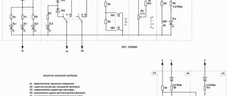
Ignition circuit Kalina 2
1 – oil pressure warning lamp sensor; 2 – generator; 3 – throttle pipe with electric drive; 4 – coolant temperature sensor; 5 – ignition system wiring harness block to the instrument panel wiring harness block; 6 – solenoid valve for purge of the adsorber; 7 – air conditioning system pressure sensor; 8 – mass air flow sensor; 9 – crankshaft position sensor; 10 – oxygen concentration sensor; 11 – controller; 12 – diagnostic oxygen concentration sensor; 13 – blocks of the wiring harness of the ignition system and the wiring harness of the ignition coils; 15 – ignition coils; 16 – spark plugs; 17 – nozzles; 18 – blocks of the wiring harness of the ignition system and the wiring harness of the injectors; 19 – phase sensor; 20 – knock sensor.
Wiring diagrams Lada Kalina 2 hatchback (luxury)
| This section contains electrical diagrams for the new Kalina (VAZ 2192) luxury version. |
Front wiring diagram Kalina 2
Wiring diagrams for Lada Kalina 2 hatchback (luxury).
electric Lada Kalina 1 – right headlight; 2 – electric motor for washers; 3 – left headlight; 4 – starter; 5 – rechargeable battery; 6 – main fuse block; 7 – generator; 8 – sound signal; 9, 10, 11 – front wiring harness blocks to the instrument panel wiring harness blocks; 12 – air conditioning fan electric motor; 13 – electric fan of the engine cooling system; 14 – ABS hydraulic unit; 15 – right front speed sensor; 16 – left front speed sensor; 17 – front wiring harness block to rear wiring harness block; 18 – right fog lamp; 19 – left fog lamp; 20 – ambient air temperature sensor; 21 – reverse lamp switch; 22 – air conditioning compressor; 23 – audible alarm signal; 24 – rear window washer electric motor.
Instrument panel diagram Kalina 2
1,2 – blocks of the instrument panel wiring harness to the blocks of the front wiring harness; 3, 4 — blocks of the instrument panel wiring harness to the blocks of the rear wiring harness; 5 – lighting control module; 6 – ignition switch; 7 – on-board computer mode switch; 8 – windshield wiper switch; 9 – instrument cluster; 10 – light signaling switch; 11 – trunk lock drive switch; 12 – diagnostic block; 13 – block of the instrument panel wiring harness to the block of the wiring harness of the air supply box; 14 – rear window heating switch; 15 – alarm switch; 16 – brake signal switch; 17 – multimedia system; 19 – rotating device; 20 – driver airbag module; 21 – sound signal switch; 22 – mounting block: K1 – relay for the electric fan of the engine cooling system; K2 – door lock relay; K3 – additional starter relay; K4 – additional relay; K6 – windshield wiper relay; K7 – headlight high beam relay; K8 – sound signal relay; K9 – relay for low beam headlights; K10 – relay for turning on the heated rear window; K11 – main relay; K12 – fuel pump relay; 23 – electric power steering; 24 – cigarette lighter; 25 – lampshade lighting of the glove box; 26 – glove box lighting switch; 27 – block of the instrument panel wiring harness to the block of the ignition system wiring harness; 28 – engine control system controller; 29 – block of the instrument panel wiring harness to the block of the rear wiring harness 4; 30 – electronic accelerator pedal; 31 – additional resistor; 32 – heater electric motor; 33 – solar radiation sensor; 35 – relay (K13) of the electric fan of the engine cooling system 3; 36 – compressor relay (K16); 37 – relay (K14) for heating the windshield; 38 – relay (K15) for heating the windshield 2; 39 – headlight range control regulator; 40 – clutch pedal position signal switch; 41 – passenger airbag module; 42 – evaporator temperature sensor; 44 – windshield heating element; 46 – windshield heating switch; 47 – central unit of body electronics; 48 – micromotor reducer of the air flow distributor damper; 50 – controller of the automatic climate control system; 51 – micromotor gearbox for mixing air flows; 52 – micromotor gearbox for recirculation damper drive.
All other schemes are suitable for the “norm” and “standard” configurations.
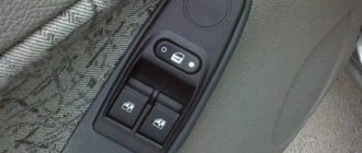
pinout of Kalina switches – Snobdenie
Light control module 118 help with pinout - Connector for power window switch block Kalina 2. Kalina 11183 Repair Electrical diagrams! Please help with pinout. I downloaded electrical diagrams for viburnum on the internet. Repair of VAZ Kalina 9 - power window switch. Connector for power window switches Kalina (2 buttons) 10 terminals assembled. And they additionally need a GPS antenna and a switch. I searched for a long time on the Internet and electrical circuits for pinouts. 11 — on-board computer mode switch; 12. To the door lock switch in the switch block: 3. Lighting control module Lada - Kalina VAZ - 1117, 1118 External switch. Lada 2114 owner story – electrical and electronics. Good evening I’ll add here the pinout of the steering column contacts. Windshield wiper and washer switch; 25 - switch. In general, I bought an outdoor lighting switch with illumination from the nine. Electrical diagrams for the new Kalina 2 Hatchback. Home Lada Kalina Instrument panel pinout. Pinout of ECU connection block January 7, bosch m7. The Lada Kalina car uses a headlight unit. Then the current flows to switch 4 Electrical diagram of the instrument panel Kalina 2. Electrical equipment GAZ (21, 2410, 3102, 31029, 3110) and pinout when changing the tidy (combination. Diagram, pinout of the electrical package controller 2170 - 3763040 - 00 VAZ 2170 Priora Sound switch. Need pinout of instruments for Lada Priora and Kalina. Steering column switch on VAZ2104 from tens of Kalina. And buy Kalina steering column switches. Ignition switch 2170 pinout Detailed Pinout El. Squeezing the spring clamps of the right switch, remove it from the connector together. Some owners of Lada Kalina 2nd generation. Door lock; 4 - switch block; 5. Kalina control unit - sent to Lada Kalina: Electrics: Greetings Kalinovodov. All about the mounting fuse block on the Lada Kalina, where it is located, diagram and explanation. Kalina glass lift buttons hold more pleasantly. On cars Lada Kalina VAZ 1118 is equipped with a standard electronic alarm.Coils On VAZ 1118 Kalina cars. An electromechanical one was installed on the Lada Kalina. Pinout of fuse box Kalina Lux Relay and fuse box Lada Kalina, not. All files in the category ECU firmware for Lada Kalina - optimization of vehicle performance. They claim that 2 switches with 2 positions can only have 4 options. Hi all! I decided to upgrade the instrument cluster. Wiring diagram for LADA KALINA and other units. Electrical diagrams for Kalina 2 Universal. On-board computer mode switch. Location and purpose of fuses in the fuse box of the Lada Kalina car. The pinout is useful in any case. Replacing the oil pressure sensor on Lada Kalina; Corolla 1999 fuse pinout. Lada Kalina pinout of alarm unit aps 6. Lada Kalina: all information about VAZ cars of the Lada Kalina family: VAZ 1117 station wagon. ELECTRICAL CONNECTION DIAGRAMS FOR CARS OF THE lada kalina FAMILY V. Dashboard on the second generation Kalina. Purpose, principle of operation and design of steering column switches VAZ 2108 2109 21099.
Delivery by Russian Post (cash on delivery, no prepayment)
Lada Granta instrument panel pinout
Advantages: the most widespread network in Russia, delivers to any corner of the country, including remote ones. Flaws:
- high cost of delivery of heavy or large parcels, as well as the weight of one parcel should not exceed 20 kg;
- long delivery times and queues in large cities for receipt.
To send your order by Russian Post:
Delivery time may vary depending on how far your locality is from Togliatti and usually ranges from 5 to 14 days.
The cost of delivery is calculated based on the volume, weight of the selected product and the distance to the recipient's settlement.
Required for sending:
- indicate full name recipient;
- Your mailing address;
- Your phone number (contact);
- Post office code.
Russian Post commission for cash on delivery service:
- purchase price up to 1,000 rubles. – 70 rubles + 5% of the amount;
- purchase price from 1,000 to 5,000 rubles. – 80 rubles + 4% of the amount;
- purchase price from 5,000 to 20,000 rubles. – 180 rubles + 2% of the amount;
- purchase price from 20,000 to 500,000 rubles. – 280 rubles + 1.5% of the amount.
Russian Post - Delivery of goods up to 20 kg throughout Russia. https://www.pochta.ru
Delivery time and cost Track the parcel Calculate delivery by mail
Connecting Kalina fog lights
Lada Kalina first generation: technical characteristics of the model. Lada Kalina station wagon weight
In addition to fog lights and mounts, the kit should include wiring, which is often missing. We recommend that you purchase several meters of wire with a cross-section of at least 0.75 sq. mm. We pull the wires from the engine compartment into the passenger compartment using a piece of wire on the starboard side through the hole above the clutch pedal. To gain access you will need to remove the front left wheel and fender liner.
The most practical places to install the PTF button are in the tunnel, or on the panel instead of the air conditioner button.
A less popular method is to connect the PTF to the light control module (LCM). We fix the relay with a hinged mount in the mounting block.
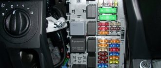
Protective components
Energy consumers in the on-board network of the Lada Kalina are protected by two types of elements:
- fuses;
- electromagnetic relays.
The fuses are equipped with special fusible elements that burn out when the current passing through the insert increases above the permissible limit. The fuse is connected to the current collector it protects using a series circuit.
Fuse links are enclosed in certain blocks, also called mounting blocks. One is located in the cabin, and the second under the hood. Each fuse protects its own section of the circuit. The element is able to withstand a certain amount of maximum current. It is this maximum that a specific fuse is designed for, so when replacing it, it is necessary to select an analogue with an identical current value.
The block contains 28 fuse links. This number contains 4 elements as a reserve. Their current ratings are: 2 A, 7.5 A, 10 A, and 20 A.
To enable additional inserts to be included in the circuit, the block has three free slots. The total number of fuses is the same for any body version of the Lada Kalina, be it a sedan, etc.
The relay is presented in the form of a device that allows the circuit to be closed or disconnected at the required moment. Relays are also present in the previously mentioned blocks.
The first mounting module contains relays responsible for the functionality:
- window lifters;
- turn signals;
- windshield wipers;
- horn;
- distant lighting elements;
- glass blowing systems.
In addition, relays provide such auxiliary functions as:
- front headlight washer;
- fog lighting devices;
- heated seats in the cabin.
The engine control unit contains relays that control the following components:
- ignition;
- connecting the fuel pump;
- turning on the electric fan.
The module itself is located in the cabin below the front panel. To provide access, you will need to remove the right trim on the console by unscrewing the fastening component.
Rear wiring diagram Kalina 2
1, 2 – rear wiring harness blocks to the instrument panel wiring harness blocks; 3 – right side direction indicator; 4 – left side direction indicator; 5 – hand brake sensor; 6 – rear wiring harness block to the tailgate wiring harness contacts; 7 – interior lighting unit; 8 – switch in the driver’s seat belt; 9 – trunk lighting; 10 – electric fuel pump module; 11 – right lamp; 12 – rear wiring harness block to the tailgate wiring harness contacts; 13 – left lamp; 14 – rear wiring harness block to rear left door wiring harness block; 15 – rear wiring harness block to rear right door wiring harness block; 16 – rear wiring harness block to the front right door wiring harness block; 17 – rear wiring harness block to the front left door wiring harness block; 18 – airbag control unit; 19 – rear wiring harness block to the front wiring harness block; 20 – block of the rear wiring harness to the block of the wiring harness of the parking system sensors; 21 – control unit and alarm unit of the safe parking system; 22 – parking system switch; 23 – speaker of the safe parking system; 24 – switch for interior lighting in the driver's door pillar; 25 – interior light switch in the right front door pillar; 26 – switch for the interior lighting in the pillar of the right rear door; 27 – interior light switch in the left rear door pillar; 28 – right seat electric heater switch; 29 – left seat electric heater switch; 30 – electric heater of the right seat; 31 – electric heater of the left seat; 32 – driver’s seat belt pretensioner; 33 – passenger seat belt pretensioner; 34 – central unit of body electronics; 35 – sensor for automatic glass cleaning system (rain sensor); 36 – rain sensor sensitivity regulator; 37 – rear wiring harness block to the instrument panel wiring harness block; 38 – right rear speed sensor; 39 – left rear speed sensor.
Album of schemes for "VAZ 1118"
The Lada Kalina technical manual has such an album. The general scheme includes 59 components, among which you can find:
- sources and consumers;
- protective and control elements;
- ECU;
- sensors
A separate printed block displays the electrical circuit for connecting the electronic motor control module with other system components. We are talking about spark plugs, injectors, sensors, and the ignition unit of the Lada Kalina car.
There is also a separate electrical diagram that highlights the front and rear cable harnesses. A detailed display of all connections of the electrical components of the front panel in the cabin is provided. In addition, the diagram contains clear connections for the wiring harnesses of the door panels and the interior ventilation unit.
In order for the cable connections to ensure reliable contact, they are connected to special blocks with terminals. All terminals are compatible with cable harnesses, the wires of which have their own characteristic sheath color. Each electrical diagram in the album is designed in such a way that the color shade of the sheath of a particular cable actually matches the color shown in the documentation.
Numbers are written next to the drawn lines, allowing you to use the symbols to determine the connector to which a particular wire fits. For example, the marking on the “9/14” diagram “tells” us that this cable is connected to the 9th block via connector No. 14.
Did you like the article? Follow our channel for new ideas of useful car tips. Subscribe to us in Yandex.Zen. Subscribe.
Since 2004, the LADA Kalina model has appeared in the production program of the Volzhsky Automobile Plant. The automaker consciously moved to develop a new platform, presenting its prototypes in various bodies - a hatchback in 1999, a sedan in 2000 and a station wagon in 2001.
CBKE errors
- * there is no fault code in TsBKE 21900-3840080-10;
- If an “active” fault code is detected, perform the checks outlined in the “diagnostics” column;
- After troubleshooting, clear fault codes using a diagnostic tool.
Deciphering fault codes
:
- B1002 Open in driver lock control circuit
- B1004 Open in the front left window control circuit
- B1006 * Open in the rear left window control circuit
- B1008 Open in the alarm sound control circuit
- B1010 Open in the trunk gear motor control circuit
- B1012 Open in the passenger lock control circuit
- B1014 Open in the front right power window control circuit
- B1016 * Open in the rear right window control circuit
- B1017 ROM checksum error of the central unit of body electronics
- B1018 Short circuit in the rear window heating relay coil circuit
- B1019 Short circuit in the windshield heating relay coil circuit
- B1020 Short circuit in the seat heater relay coil circuit
- B1021 Wiper malfunction
- B1023 Short to ground or overheating in the control circuit of the common board bus
- B1027 Malfunction of the power window control keys in the passenger doors
- B1028 * Short to ground in the rain sensor sensitivity regulator circuit
- B1030 Open circuit (lamp burnout) of daytime running lights
- B1031 * Open circuit in the rain sensor sensitivity regulator circuit
- B1033 Open (lamp burnout) in the left turn signal circuit
- B1034 Open (lamp burnout) in the right turn signal circuit
- B1040 Open or short to ground in the low beam headlight relay coil circuit
- B1041 * Short circuit in the automatic lighting control relay coil circuit
- B1042 Short circuit in the high beam relay coil circuit
- B1043 Short circuit in the low beam relay coil circuit
- U1044 Lack of communication with MDV
- U1045 Communication error with MDV
- U1046 * Communication error with rain and light sensor
- U1047 * No communication with rain and light sensor
- U1048 CAN bus fault
- B1049 High voltage on-board network
- B1050 Low voltage on-board network
- B1051 * Short to ground in the right mirror control circuit
- B1052 * Left Mirror Control Circuit Malfunction
- B1057 Internal malfunction of the MDV
Also using this program you can configure the central unit of the body electronics.
Set the delay for turning on the wipers after the washer is activated (from 0 to 2.56 sec).
Activate or deactivate the function of turning on the interior lamp when the ignition is turned off
Set the delay for turning off the interior lamp when closing the door (from 0 to 60 sec)
Set the delay of the energy saving mode (power loss on the interior lamp, trunk, control wire of the radio (Kalina 2) (from 0 to 10 min)
Activate or deactivate the stepwise door unlocking mode, as well as the automatic door unlocking mode when the ignition is turned off
Activate or deactivate the automatic mode of raising/lowering the driver's window
More details about the TsBKE block are described in Technological Instructions (TI) 3100.25100.12051, which you can download here.
All reference information on models
:
- Lada Granta
- Lada Kalina
- Lada Priora
Keywords: Lada Priora windshield wipers | windshield wipers for Lada Granta | windshield wipers Lada Kalina | heating for Lada Granta | heating Lada Kalina | heating for Lada Priora | external lighting for Lada Granta | external lighting for Lada Priora | external lighting for Lada Kalina | interior lighting for Lada Granta | interior lighting for Lada Kalina | interior lighting for Lada Priora | window lift for Lada Kalina | window regulator for Lada Granta | Lada Priora window regulator
5
Found an error? Select it and press Ctrl+Enter..
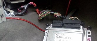
Replacement features
Briefly about the procedure for replacing the control module on Kalina 2:
First, the instruments are dismantled from the center console; there is nothing difficult about it. Then the lower part of the center console trim is unscrewed, the trim is removed, and you gain access to the fuse and relay box. The mounting block with safety devices can be unscrewed, but it cannot be removed because it is connected by wires. You can rotate it a little so that it takes a horizontal position. You can stick your hand into the gap formed as a result of turning. Having done this, you will be able to feel the shelf on which the TsBKE is installed. A little to the left there is a bolt with which this module is fixed - you need to unscrew it. After this, through the top, through the instrument panel, you will need to disconnect the two connected connectors
After completing these steps, you can carefully dismantle the CBKE and remove it by slightly moving the fuse box. Please note that you should not pull the device too hard, since on the other side there are two more connectors that will need to be disconnected
When the wires are disconnected, the CBKE can be completely dismantled and repaired or replaced.
Windshield cleaner and washer
The Lada Kalina windshield cleaning system includes:
- Electric motor with gearbox;
- Set of levers and brushes.
The diagram below shows:
- Electric washer fluid reservoir pump;
- Standard ignition switch;
- Control unit for electric motor operating modes;
- The windshield wiper motor itself;
- Fuse and relay block;
- Terminal “A” from the power supply.
For reference: To protect the engine from overloads, a bimetallic fuse is used, the price of which is much lower than the cost of repairs.
Washer kit includes:
- Polyethylene tank with pump;
- Injectors located on the hood of the car;
- Set of flexible connecting hoses.
Connecting Kalina fog lights
In addition to fog lights and mounts, the kit should include wiring, which is often missing. We recommend that you purchase several meters of wire with a cross-section of at least 0.75 sq. mm. We pull the wires from the engine compartment into the passenger compartment using a piece of wire on the starboard side through the hole above the clutch pedal. To gain access you will need to remove the front left wheel and fender liner.
The most practical places to install the PTF button are in the tunnel, or on the panel instead of the air conditioner button.
A less popular method is to connect the PTF to the light control module (LCM). We fix the relay with a hinged mount in the mounting block.
Which headlights to choose
Factory technology provides for the installation of headlights in a luxury configuration. Indeed, today such products are produced by many manufacturers, large and small.
The following types of products can be found in the retail chain:
- Products under the Bosch brand are always sold as a set (2 pieces) and are distinguished by fairly durable glass and good quality luminous flux. We can say that this is the most reliable option, but its price is noticeably higher than all other analogues.
- Production PTFs are in many ways similar to those described above, but in fact their quality is noticeably inferior to the first option. The only advantage is lower cost.
- Kirzhach fog lights on Kalina have lens-shaped convex glass, which allows you to concentrate the light flux and direct it exactly where it is required. Quite a good and reliable solution.
- Products under the ProSport brand and other similar brands are produced by Chinese factories. It is difficult to judge their reliability and quality, since one option can be excellent, while the second one will fail in a very short time.
Bosch products play leading roles here too
The question of which fog lights are better for Kalina raises a number of disputes, so the decision is yours. As practice shows, the most popular options are Bosch and Kirzhach.
Replacement and repair of the electrical package control unit 2170-3763040 Lada Priora
Priora electrical package control unit 2170-3763040 (Comfort unit)
The equipment of the car, as is sometimes written, does not matter when a unit with a given number is installed.
The electrical package controller is a device designed for installation on VAZ 2170 Priora cars. It controls many car functions, for example, turn signals, power windows, instrument panel lights, side lights, low beam, fog lights, reverse lamp, interior lighting, heated rear window.
This controller is installed in the central, lower part of the dashboard above the ECU unit. To remove it, you need to remove the lower sides of the torpedo. Using a socket wrench 10, unscrew the two nuts.
Priora electrical package control unit housing 2170-3763040
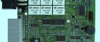
Priora electrical package control unit board 2170-3763040
Location of terminals of the Priora electrical package control unit 2170-3763040
Diagram of the Priora electrical package control unit 2170-3763040
Purpose of parts on the board of the Priora electrical package control unit 2170-3763040
POS - interior lighting lamp ZPTO - rear fog lights BS - low beam PTF - fog lights MDV - driver's door module PUP - turn signal switch PAS - hazard warning switch PPD - front right door PLD - front left door ZPD - rear right door ZLD - rear left door PS - passenger door power window switch FOB - trunk light ZP - right mirror ZL - left mirror GO - side lights UP - direction indicators
At this link you can see additional information on the above unit and others: www.chiptuner.ru/content/usp_norma Problem with the electrical package control unit 2170-3763040 Priora:
Priora electrical package control unit 2170-3763040 old
After turning on the heated rear window, a malfunction occurred in the operation of this unit. The IMMO started flashing, the emergency lights came on - it’s impossible to turn it off. After turning off the heating, the turn signals and emergency lights, mirrors stopped functioning, the central locking stopped working, both from the key and from the buttons in the cabin, the tidy went out, and the power windows stopped working.
A new electrical package control unit 2170-3763040 Priora was installed:
Electrical package control unit 2170-3763040 new
The procedure for removing and installing the block is simple. There is no need to retrain the key, everything works. The only thing is that the two-level door opening system stopped working. Now one click opens two doors. or one press and only the driver's door opens, a second press and the passenger door does not open... Strange.
Repair of electrical package control unit 2170-3763040 Priora:
In the old unit, for the sake of experiment, two VN5016AJTR-E power driver microcircuits (SSO-12) were replaced
VN5016AJTR-E
Resoldering the VN5016AJTR-E chips did not bring any results.
Resoldered chip: MCZ33972EW
Chip MCZ33972EW for replacement.
https://www.drive2.ru/l/8689917/
next article:
Ignition key and remote control 1118-3763070-01 in Lada Priora
The remote control (RC) is designed for remote control of locking and unlocking
Rating 0.00
Basket
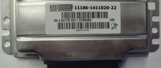
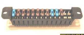
Double-glazed window control unit “Norma” 1118 – 6512010 for VAZ 11183 “Kalina”
Aktuator On cars of the Kalina family, 2 types of non-interchangeable (by wiring) glass unit control controller 1118 - 6512010 and 11180 - 3763040 can be installed. 1118 – 6512010 has one 25-pin connection connector, 1118 – 3763040 (1118 – 3763040 – 10) – two connectors.
Remote control system for double-glazed windows “norm” on a VAZ 11183, Kalina. Controls power windows and central door locking. When the connector is removed, the engine does not start; the device performs some of the anti-theft functions.
Connection
| № | Wire color | Purpose, addressing |
| 1 |
* A regular shock sensor from any alarm system (Alligator, Saturn, Clifford, APS) is suitable.
+ 12 V connect to pin 12; body – on the 6th; We connect the signal wire (a ground appears on it at the moment of activity) to the 1st contact.
During normal arming, Kalina now reacts to an impact on the body (it sounds a horn and blinks turn signals). Similarly, instead of a shock sensor, you can connect a volume sensor (for example, single-level MMS‑1).
You can also connect a pager: + 12 V of the pager transmitter on pin 12, minus on pin 21.
Double-glazed window control unit 1118 – 3763040 (- 10 ) for VAZ 11183 “Kalina”
| External shock or volume sensor input (Not used)* | ||
| 2 | Pink/Black | To the door lock switch in the switch block |
| 3 | Brown/Green | K-Line. To Kl. 71 ECM, Cl. 18 APS‑6 |
| 4 | Brown | Connects to ground when the driver's door is closed |
| 5 | Grey | To rear window heating element |
| 6 | Black | Weight |
| 7 | Pink/White | To the door lock switch in the switch block |
| 8 | Yellow/Blue | In the instrument cluster, to the APS-6 indicator |
| 9 | Black/White | Connects to ground when opening the hood. C VK engine compartment lamp |
| 10 | Two White/Red | Connects to ground when opening the rear doors |
| 11 | Brown/Red | Connects to ground when opening the right front door |
| 12 | Output 12 V power supply for external sensor (Not used)* | |
| 13 | Not used | |
| 14 | Yellow | Pulse + 12 V, closing all doors and trunk |
| 15 | Red/Blue | To class 14 APS‑6 |
| 16 | Blue with Black | To the left direction indicator |
| 17 | Red/Blue | Impulse + 12 V, opening passenger doors |
| 18 | Red/Black | Pulse + 12 V, driver's door opening |
| 19 | Pink/Red | Impulse + 12 V, opening the trunk lock |
| 20 | Yellow/Blue | To terminal “15”, through fuse F 9, in the mounting block |
| 21 | Grey/Black | "-" Horn relay |
| 22 | White/Blue | Connects to ground when the driver's door is opened |
| 23 | Red | To permanent plus through fuse F 5, in the mounting block |
| 24 | Blue | To the right turn signal |
| 25 | White black | Connects to ground when opening the trunk |
| Controller board | ||
| Controller board |
Sign
| Possible reasons | Elimination method |
| The key code is not readable |
1 . 1 Malfunction in the VZ communication coil circuit
1 . 2 Malfunction in the circuit from the block to the communication coil to the APS ECU
1 . 3 Transponder missing in OK
1 . 4 The transponder in OK is faulty (detected during pre-production preparation)
1 . 5 The transponder in the Republic of Kazakhstan is faulty (detected during pre-production preparation)
1 . 6 Malfunction of the input transponder circuit in the APS ECU
1 . 8 The communication coil came off from the VZ pad on the inside
Abbreviations: IS – status indicator; VZ – ignition switch; OK – training key; RK – working key; RC – remote control; KSUD – engine control system controller; ECU - electronic control unit
The Kalina electrical package control unit is used to automatically raise and lower windows and control doors. Additionally, it makes it possible to control alarm activation and trunk opening.
If we are talking about the luxury configuration of Kalina 2, then the electrical package control unit is responsible for blocking the ignition switch. That is why any malfunctions in its operation negatively affect the driving performance of the vehicle.
Delivery by transport company (cash on delivery, no prepayment)
Advantages:
- the cost of delivery of heavy and large-sized orders is much cheaper than that of Russian Post;
- There are practically no restrictions on the weight and dimensions of cargo;
- There is a wooden crate service - this is an additional guarantee of the integrity of the order.
Disadvantages: unfortunately, there are branches only in cities.
The estimated cost of delivery for an order up to 30 kg is 450 rubles.
List of transport companies with which we cooperate:
- TC "PEK" (cash on delivery service available);
- TC "Business Lines";
- TC "Energia";
- TC "KASHALOT" (KIT) (cash on delivery service available);
- TC "SDEK" (cash on delivery service available);
- TC "DPD";
- TC "ZhelDorExpedition";
- TC "VOZOVOZ";
- TC "Baikal-Service".
To send your order by transport company:
The cost of delivery is calculated based on the volume, weight of the selected product and the distance from the city of Tolyatti.
To send an order you must:
- indicate full name recipient;
- Your locality and region;
- series, number of passport or driver's license;
- Your phone number (contact).
TC "Business Lines" - Urgent delivery of goods from 1 kg throughout Russia. The exact cost can be found on the official website of the delivery service - https://www.dellin.ru
Delivery time and cost Track the parcel View the list of branches
TC "PEK" - Guaranteed safety of cargo for the entire duration of cargo transportation, clear information support, delivery of goods throughout almost the entire territory of Russia, Belarus and Kazakhstan in optimal terms and accurately calculated cost of services. The exact cost can be found on the official website of the delivery service https://pecom.ru/ru/calc
Delivery time and cost Track the parcel View the list of branches
TC "SDEK" - Low tariffs compared to foreign courier companies, while the quality of the services provided meets modern international logistics requirements. Developed network of own representative offices. The exact cost can be found on the official website of the delivery service https://www.cdek.ru/calculator.html
Delivery time and cost Track the parcel View the list of branches
TC "ZhelDorExpedition" - Serves only large cities and towns. The exact cost can be found on the official website of the delivery service - https://www.jde.ru/branch
Delivery time and cost Track the parcel View the list of branches
TC "Energia" - Cargo transportation in Russia, CIS and China. The exact cost can be found on the official website of the delivery service https://nrg-tk.ru
Delivery time and cost Track the parcel View the list of branches
TC "KASHALOT" (KIT) - Delivery of cargo from 1 kg to 20 tons throughout Russia and Kazakhstan. The exact cost can be found on the official website of the delivery service https://tk-kit.ru/calculate
Delivery time and cost Track the parcel View the list of branches
TC "Baikal-Service" - Transportation and delivery of consolidated cargo by road across Russia. The exact cost can be found on the official website of the delivery service https://www.baikalsr.ru
Delivery time and cost Track the parcel View the list of branches
TC "DPD" - Transportation and delivery of groupage cargo by road in Russia. The exact cost can be found on the official website of the delivery service https://www.dpd.ru
Delivery time and cost Track the parcel View the list of branches
TC "VOZOVOZ" - Transportation of groupage cargo by regular delivery routes between Russian cities. The exact cost can be found on the official website of the delivery service https://vozovoz.ru
Delivery time and cost Track the parcel View the list of branches
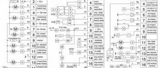
Ignition circuit Kalina 2
1 – oil pressure warning lamp sensor; 2 – generator; 3 – throttle pipe with electric drive; 4 – coolant temperature sensor; 5 – ignition system wiring harness block to the instrument panel wiring harness block; 6 – solenoid valve for purge of the adsorber; 7 – air conditioning system pressure sensor; 8 – mass air flow sensor; 9 – crankshaft position sensor; 10 – oxygen concentration sensor; 11 – controller; 12 – diagnostic oxygen concentration sensor; 13 – blocks of the wiring harness of the ignition system and the wiring harness of the ignition coils; 15 – ignition coils; 16 – spark plugs; 17 – nozzles; 18 – blocks of the wiring harness of the ignition system and the wiring harness of the injectors; 19 – phase sensor; 20 – knock sensor.
Personalize existing features
The manufacturer has provided for the timing of regular technical inspections, which are mandatory. For non-compliance, the company reserves the opportunity to deprive the car owner of the right to free service.
The most vulnerable is the comfort block, which includes many logical circuits. Its purpose boils down to the following functions:
- activation of interior lighting;
- adjusting the operation of car alarms;
- turning on the heated rear window;
- automatic mirror adjustment;
- control of electric windows;
- remote control of locks.
The manufacturer has provided the ability to personalize each element. To do this, the electrical package control unit must be recoded at an authorized automotive center. Using official software, the wizard will add or remove certain features. If everything is done correctly, 20 minutes after requesting the appropriate service, you can safely use the “iron horse”.
According to reviews from car enthusiasts, the Lada Kalina car is distinguished by electronic filling with increased sensitivity to operating conditions. Aggressive driving style and minor damage lead to malfunctions.
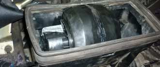
As a result, you need to visit a service station to replace the device. To do this, remove the control unit, which must be done as follows:
- turn off the battery;
- unscrew the screws from the driver's seat;
- Use a ratchet wrench to remove the nut;
- the plastic plug is squeezed out completely;
- carefully pull out the seat;
- remove the seat by dismantling the terminals;
- remove the cover plate.
Lighting control modules (LCM) 344.3769, 345.3769. Pinout.
Lighting control modules (LCM) 344.3769, 345.3769. Pinout.
Connection: block 1118-3724500. Applicability: Lada Kalina (1117, 1118, 1119). Lighting control module Lada Kalina.
Lighting control modules 344.3769, 345.3769 are designed for switching electrical control circuits for external lighting, front and rear fog lights, adjusting the level of illumination of controls and instruments, and controlling the angle of the light beam of automobile headlights.
Numbering and assignment of contacts. Contact
| Purpose | |
| G | to the gearmotor of the headlight range control |
| 56b | to the gearmotor of the headlight range control |
| 58b | to backlight sources |
| 31 | "Weight" |
| Xz | + 12 V (from terminal “15” of the ignition switch) |
| 56 | to the low/high beam headlight switch |
| 1 | from rear fog lights |
| 2 | to the rear fog lamp relay |
| 3 | from the front fog lights (only for MUS 345.3769) |
| 4 | to the front fog lamp relay (only for MUS 345.3769) |
| 58 | to side lamps |
| 30 | + 12 V (from terminal “30” of the ignition switch) |
Main characteristics.
Rated voltage, V: 12.
Rated load:
- Active: 2 mA pin G, 0.001-0.1 A pin 2 (load is switched to pin 31).
- Inductive, at 100 mH: 0.15 A pin 4.
- Tube: 35 W (3.3 A) pin 58b, 10 A pin 56 and pin 58.
Viewing surface color: black.
Character color: white.
Symbol backlight color: light green.
Indicator illumination color: rear fog lights - yellow, front fog lights - light green.
Power supplies
In the on-board network of the model we are considering, all pantographs operate at a voltage of 12 V and consume direct current. The electrical circuit for their switching is single-wire.
The wiring diagram contains components that are divided into 4 categories:
- energy sources;
- its consumers;
- protective components;
- sensors
The “representatives” of the first two groups, with their negative terminals, are connected via wires to the body, which appears as “ground”. If we talk about the sources, then there are two of them in the car: the battery and the generator set. When the engine is running, the generator produces power, and when the engine is stopped, the battery is “occupied” with supplying the current collectors with electricity. The generator unit recharges the battery during its operation.
The principle of operation of the generator is quite simple. By means of a belt drive from the rotating crankshaft pulley, the rotor of the generator unit is driven in a circular motion. Thus, alternating current is generated, which is converted into direct current by means of a rectifier module. Over time, the rotor shaft bearings become unusable. They initially contain a lubricant, which gradually loses its properties. The stator of the device has a three-phase winding and is connected to the cover with four studs. There is also a voltage regulator in the generator unit. He monitors that this indicator is within 14.5-15.0 Volts. Note that the rotation ratio of the motor to the generator is 1:2.4. The maximum generated current is 85A.
Lada Kalina Hatchback 2010, 80 l. With. — tuning
Lada Kalina, 2012
Comments 54
Hello, can you tell me if the front fog lights are on, what needs to be switched off so as not to burn anything? There is no MUS, I need to check!
I actually threw out this block, installed 2 4-pin relays and a switch for the turn signal from a foreign car and everything worked. and thank you so much for the pinout diagram)
The dimensions are supplied with a black and white cable (58) from pin #9, which in the MUS is connected from pin #11 - pink cable (30). For the low beam there is a green cable (56) from contact #12, which in the MUS is connected from contact #10 - a blue-black cable (Xz). IMHO: only contacts #10 with #12 can be shorted with jumpers without consequences. Contacts #10 and #9 are never bridged in the ICC, respectively, when they are bridged and the knob is turned to the “dimensions” or “low beam” position, contacts #10 and #11 (pink and blue-black cables) are bridged. Hence your phenomenon of the engine running without a key since 12 volts are sent to the ignition in the opposite direction through the blue-black cable. How unsafe this is for electrical and electronics is doubtful for me personally...
Safe, I tried it. When installing a jumper between contacts 10 and 9 and turning on the ICU in the “dimensions” position, contacts 9, 10 and 11 are connected, and in the “low beam” position 12 is added to them, that is, ALL four are connected (as if both jumpers). But it’s also a plus in Africa, it can’t go in the “that” or “reverse” direction, plus 12V plus 12V can’t be burned out, at least in this case. Yes, the ignition is kept on if you set the MUS to “dimensions” (it also turns on without a key, as if the key was inserted and turned to the ignition: the instrument lights up, the heater fan turns on, etc.). This also seemed convenient to me, the previous car had autostart, but this one does not have it YET, but thanks to MurZone, now we know an intermediate solution on how not to freeze next to the car while it is warming up. It’s a pity that when the ignition is on, the doors do not close with the key (although they OPEN), but if necessary, they can be closed manually mechanically. I decided to go a little further and not just threw a jumper, but soldered taps to all four wires (9,10, 11 and 12) and brought them out into two relay blocks - maybe someday I’ll implement more complex on-off algorithms (then You will also need a minus from pin 8). In the meantime, instead of a relay, I stuck a jumper between 10 and 9 and am very pleased. By the way, if for some reason you don’t want the ignition support effect when the lights are on, just put a diode in the jumper.
We activate the front PTF button in the MUS from normal.
We activate the front PTF button in the MUS from normal.
Schematic diagram of the ICC
This modification applies only to the new MUS model, with a vertical connector in a compact thin case.
First, open the ICC.
To remove the low beam and parking light switch, use a cloth or several layers of paper, placing them under the jaws of the pliers, apply a little force, and pull it.
Attention! The latches are filled with glue; carefully release the latches with a straight thin screwdriver or a utility knife.
Be careful not to lose the plastic freewheel spring ends.
The ICC has been opened and the board has been removed.
photos of individual areas.
As you can see, the board does not have enough parts to use the PTF button function. Our task is to add them there.
To finalize, we will need to find a relay marked 21.3777MS
namely MS from the manufacturer ABAR. Attention shortage!
The main thing is to make sure that there is an 8-pin AS195 microcircuit on the relay board! datasheet
The housing and printed circuit board of the required relay looks something like this (the board is already without components).
If you have the opportunity to open the relay when purchasing, take advantage of it, so as not to buy the wrong relay.
Below are photos of relays that look the same but with a different filling, be careful, you don’t need to buy such relays!
If you find the required relay 21.3777MS (emergency), then solder it from its board to the MUS board:
- chip AS195 DA2A
— transistor BCP56-16 in VT2. - Zener diode BZX 79C 6V2RL in VS1.
SM4005 (1N4001-1N4007 or S1J) in VD6, VD7, VD8, VD9.
HL5 (PTF included, orange).
8.2 kOhm in R28, R24
510 Ohm in R27 910 Ohm in R4
- micro-relay from K1 to K1.
— solder two pins (male) of contacts 3 and 4 of the MUS (taken from the same relay).
— microswitch without fixation, socket SW2.
Photo of the original MUS deluxe board
photo of the upgraded board
my version with wall mounting
Now we need to modify the PTF power button in this way. We make a partition pusher and insert it into special grooves.
We take out the springs from disposable lighters, bite off the constrictions on them, and put them on the guide rods of the button.
We drill a 3mm hole in the button in the same place as on the adjacent one; there is a landmark on the back side.
Press the foil to the hole from the front side. Fill the drilled hole with hot glue, tear off the foil and get a well-filled hole through which the glow from the PTF indication LED will pass.
When assembling the MUS, it is necessary to install the contact group in this way:
To check the result of the modification, we need to apply power to it:
Minus on “31” contact +12V on 30 and Zx then turn the knob on the block to the mode of switching on the dimensions and then you can see what is happening on the diagram (on the MUS board).
If everything is soldered correctly and the parts are all in good condition, then when you press the PTF power button, the small relay on the MUS board should click, and +12 volts should appear on pin 4, close contacts 3 and 4, the indication LED should light up.
I express my deep gratitude to “Andrey710” for their help in the appearance of this article.
Kalina 2 front wiring diagram
1 – right headlight; 2 – electric motor for washers; 3 – left headlight; 4 – starter; 5 – rechargeable battery; 6 – main fuse block; 7 – generator; 8 – sound signal; 9, 10, 11 – front wiring harness blocks to the instrument panel wiring harness blocks; 12 – air conditioning fan electric motor; 13 – electric fan of the engine cooling system; 14 – ABS hydraulic unit; 15 – right front speed sensor; 16 – left front speed sensor; 17 – front wiring harness block to rear wiring harness block; 18 – right fog lamp; 19 – left fog lamp; 20 – ambient temperature sensor; 21 – reverse lamp switch; 22 – air conditioning compressor; 23 – audible alarm signal; 24 – rear window washer electric motor.