The design of the “Seven” starter, as well as the entire line of VAZ “classics”, was developed almost half a century ago. Therefore, it is characterized by high energy consumption, which is especially important when trying to start a car with a dead battery in severe frosts. There are also other problems with it:
- when the starter is working, the solenoid relay does not operate;
- when the starter and relay are working, the armature does not rotate;
- the armature rotates and the crankshaft stops;
- The starter does not turn off after starting the engine.
To get rid of problems, owners install a gear starter on the VAZ 2107.
Advantages of a gear starter for VAZ 2107
Often one spare part can significantly improve the performance of a car. Installing a gear starter on a VAZ 2107 ensures trouble-free engine starting. Replacing the starter with a gear modification provides:
- quick engine start;
- increasing the service life and intervals between preventive maintenance of the starter;
- increasing energy efficiency and starter power with smaller dimensions and weight of the device.
Thanks to improved energy efficiency, the gear starter allows you to start the car even with a very discharged battery in winter. According to the owner of the “Seven” with this type of starter, the car can be started even if the battery is almost completely discharged. The gear starter saves battery charge, which is important for frequent trips over short distances, when the travel intervals between engine starts are not sufficient to fully charge the battery.
Also, the gear modification of the starter has a significantly longer service life than the standard VAZ 2107 starter.
Download the electrical diagram of the VAZ 2107 injector
The general circuit of electrical equipment consists of individual aggregate units:
- special factory connector for connecting the on-board computer. Allows you to decipher engine errors;
- tachometer indicating the number of revolutions;
- Check Engine Light;
- starter;
- air damper sensor;
- cooling fan drive for radiator;
- drive control relay;
- Engine ECU;
- crankshaft position sensor;
- electric fuel pump with control relay;
- fuel filter;
- battery and charging relay;
- egnition lock;
- idle speed sensor.
Detailed wiring in a large format with a nozzle can be downloaded from the link. A small image (300 kb), with a resolution of 1604 pixels in height and 1022 pixels in width, will allow you to carefully examine all the necessary components and parts, and will also greatly help with electrical repairs on a VAZ.
Design and principle of operation of a gear starter
What makes a gear starter more reliable and efficient?
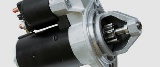
Its difference from the “classic” one is the presence of a gear transmission between the armature and the bendix. The VAZ 2107 gear starter design allows (due to high armature speeds and the use of a reduction gear) to obtain greater torque with less energy consumption, which increases the efficiency of the device. Particularly successful are solutions based on planetary gearboxes.
The principle of operation of a gear starter is no different from a conventional one - electrical energy is converted into mechanical energy.
It works like this:
- voltage is supplied to the solenoid relay, which supplies current to the winding and armature;
- the relay moves the gear along the armature shaft to the engine flywheel;
- When the power to the relay is turned off, the gear returns to its place and the starter is turned off.
The peculiarity is that the torque from the shaft is transmitted to the flywheel through a gearbox, which increases efficiency by 50%. This doubles the resource of the unit and reduces the load on the battery when starting the engine.
Device malfunctions
One of the main types of starter malfunctions is brush wear. This is due to the fact that every time the engine starts, the brushes come into contact with the armature. Current passes through the brushes, and when the armature jams, the value of this current increases to 600 Amperes. This amount of current can cause a fire in electrical wires. The wear of the brushes can be determined by the rotation of the rotor. If the rotation speed decreases or the armature does not rotate at all, then it is necessary to check the condition of the brushes.
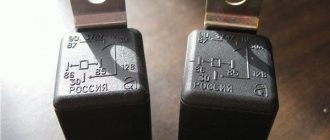
A retractor relay is attached to the starter housing, which is often the reason for the inability to start the engine. Some of the main reasons for the failure of the solenoid relay are:
- Open circuit in the relay winding.
- Destruction of any of the component parts of the device.
- Carbon accumulation or plate melting.
To troubleshoot the problem, it is necessary to determine the breakdown, but it is often easier to replace the solenoid relay with a new product. A device such as a bendix can fail. It is an overrunning clutch with a gear that meshes with the flywheel, causing it to rotate. Through the bendix, torque is transmitted from the starter to the crown of the crankshaft flywheel. The overrunning clutch, which should rotate freely in one direction and with a load in the other, can break. If the clutch fails, the starter will simply rotate idle, and a characteristic hum will be heard. In order to repair the clutch, you will need to disassemble the starter.
In rare cases, you may encounter a breakdown such as a break in the windings or plates. It is almost impossible to damage the windings, except in cases of breakdown. Most often, a malfunction with windings and plates occurs in gear starters, which is due to the unreliable design of its housing.
In order to find out the cause of the breakdown and eliminate it, you will need to disassemble the VAZ 2107 starter. First, the mechanism should be removed from the car, and then you should begin checking it. We will find out further what a mechanism check is.
How to check the starter
The simplest way to check that the mechanism is working is to connect the product directly to the battery. From the positive terminal of the battery, the wire should be connected to contact “50” on the solenoid relay, and the negative terminal should be connected to the starter housing. If a click occurs and a gear appears, then the failure is due to a fault in the supply wiring.
If the device does not function, then proceed to removing the back cover, where the brushes with brush holders are located. First you need to disassemble the starter, and then use an ohmmeter. One probe of the device is connected to the armature, and the second probe becomes alternately connected to the terminals of the windings. A working winding will show a value on the device of at least 10 kOhm.
If the test shows that the fault lies directly in the windings themselves, then further repair actions are simply useless. It is simply impossible to repair the starter winding of a VAZ 2107 with your own hands without special equipment. The problem is solved by purchasing a new engine starting mechanism.
How to repair a starter yourself
After removing the starter along with the solenoid relay from the car and checking it for functionality, you can begin repairs. It is important to remember that if the product is already quite old, then it is better to replace it. The mechanism can be repaired if one of the elements fails:
- brushes;
- solenoid relay;
- bushings;
- Bendix with fork.
Now let's look at how to repair a starter on a VAZ 2107.
- First you need to disassemble the starter by removing the back cover.
- Using a thin screwdriver, you need to remove the lock washer.
- The fastening of the brush wires must be unscrewed.
- Unscrew the mounting bolts of the solenoid relay, and then remove it.
- Using a “10” wrench, you need to unscrew the nuts from the two studs. Some starter models may have long bolts instead of studs.
- The back cover is removed.
- To remove the front cover, you will need to remove the pin along which the Bendix fork moves.
- To replace the bendix, you will need to knock out the metal ring on the rotor. In the groove behind the steel ring there is another one, which should also be opened and removed. Now you can remove the bendix and replace it with a new one.
- The plates can be cleaned with a fine scriber if necessary.
- If necessary, the bronze bushings must also be replaced. To remove the bushing you will need to use a mandrel of the appropriate diameter. The starter connection diagram is single-wire, so the “minus” is the car body and the engine block itself.
- The brushes are replaced with new ones.
- The starter assembly is performed in the reverse order of removal. After completing the assembly, you should install the starter in place and turn it on.
If the device does not function, you need to check that it is connected correctly. The design of the VAZ 2107 starter is not particularly difficult, especially for people who are familiar with electrical engineering. After the replacement, you can start your VAZ 2107 car and check the engine starting speed. Using this material, you can repair the starter on a VAZ-2107 quickly and efficiently.
Installation of a gear starter on a VAZ 2107
Replacing a starter with a gear model does not require special skills or specialized tools; you only need a standard set of wrenches. replacement is done as follows:
- Disconnect battery.
- Unscrew the starter mounting bolts and the power cable mounting nut.
- Remove the plug from the control wire.
- Pull out the old starter.
- Install the gear starter into its seat.
- Tighten the fastening bolts.
- Install the power cable and tighten with the nut.
- Attach the control wire terminal.
- Connect the battery.
You can then enjoy the ability to start your engine quickly and energy-efficiently thanks to a modern starter model.
troubleshooting
In order to correctly determine where to start, you should think about what could be the reason that the starter does not work:
- If, after you turn the key in the ignition, the engine stubbornly refuses to start, you should check the light bulbs located on the instrument panel. If they burn weakly or go out completely, most likely the reason lies in a non-functioning battery. Or it may simply be discharged. We pick up a tester and check the battery capacity and voltage;
- if the battery is fully operational, you need to check what position the speed switch is in and move it to the “P” position;
- The next thing to figure out is whether the power from the ignition switch is getting directly to the starter.
There are two ways to do the last step.
Method 1. A wire made of copper with a cross-section of 2.5 mm is inserted into the open connector. One end goes to the starter and the other to the battery terminal. Thanks to this method, it is possible to simulate ignition.
Review: Gear starter StartVolt VAZ-2101 - A powerful replacement for the standard classic starter.
View from the side of the box:
Another side surface of the package:
The next side shows the starter power, its starting speed, and the minimum temperature of its efficiency:
Starter power 1550W. significantly exceeds the power of the standard Zhiguli starter, which has a power of 1300W. The starter kit comes with a passport with a warranty card, but it all consists of advertising parts for the electrical equipment of the car manufactured by the StartVolt company. The photo shows a receipt pasted by the seller with the cost of this starter:
The starter itself in the box is carefully placed in a foam shock-absorbing cell:
At the rear end of the starter you can see its power terminals and copper parts:
The starter itself is manufactured in China under license and under the control of a Russian company, it is compact and its weight is small, about 3 kg:
The working part of the starter is somewhat smaller than the similar part of a standard starter; the gear feed mechanism and the starter fastening itself are, of course, standard:
View of the starter itself from the other side:
I would like to note the fact that the 13 wrench nut on the upper terminal at the top right in the photo (the lower nut on the copper bolt) was loosely tightened, and we managed to tighten it well. When tightening this nut, the force may cause the black cage of the round insulator of the solenoid relay to turn slightly, from where the copper bolts come out. To prevent this from happening, you need to tighten the nut carefully, without excessive lateral forces, and hold the cage itself with your hands. If the clip still turns a little, you need to carefully return it to its place with your hands and force. In the working position, this clip is fixed with an internal lock, and you can feel this fixation with your hand. In the following photo you can evaluate the comparative dimensions of the new and old standard Zhiguli starter:
The difference, as they say, is visible to the naked eye. After installing the new starter, the car's engine was started. To be honest, I was delighted when the starter was working. The speed of the crankshaft at startup is such that it seems that the spark plugs have been pulled out of the engine, and cylinder compression has ceased to interfere with the operation of the starter. The startup sound has also changed dramatically. I also liked the fact that when the starter is turned on, the voltage drop in the on-board electrical network is relatively small. So far, the operation of this starter on the car brings true satisfaction. All that remains is to wait for the winter cold and check the confidence of starting the engine in the cold. I think such a starter will be able to do it.
This is interesting: How to disassemble a spark plug
Popular reasons for electric motor failure
The most popular reasons that prevent the trouble-free installation of a power unit on a domestic classic are:
- The electric motor rotates, but does not start - first of all, you need to check for problems with the battery, timing belt and engine immobilizer by checking the components. Next, you need to disassemble the starter housing to check the armature brushes for wear and integrity of the Bendix gear;
- The starter clicks, but does not turn the engine - this malfunction may indicate wear on the armature brushes, failure of the clutch or bendix gear, as well as low battery voltage;
- When the starter is running, the crankshaft does not rotate - if you can hear the rotation of the electric motor, but the engine flywheel remains motionless, you need to check the friction teeth on the Bendix gears and the flywheel clutch;
- The pull-out relay does not work - possible problems with the contact plate or solenoid of the relay. To determine if the relay is inoperable, just connect the starter directly to the battery - if the engine starts, then the starter is working and you just need to replace the relay. If not, you will have to additionally disassemble the electric motor and inspect the bendix, rotor, stator and armature brushes;
- The starter does not stop turning after starting the engine - this is a sign of sticking of the contact plate of the pull-out relay. Also, if there is an ECU on the engine, this situation may cause emergency operation of the engine. In any case, if the starter is not turned off after ignition, the vehicle cannot be operated - otherwise the service life of the power unit will be seriously reduced.
Important to remember! Most problems with the starter occur due to a mismatch in favorable conditions for ignition of the engine - first of all, troubleshooting needs to start with the battery and wiring. It is important to check the battery charge level, electrolyte volume and the presence of oxidation at the conductive terminals, as well as evaluate the viscosity of the technical oil in the engine.
Gear starter on VAZ 2107: to install or not?
Which starter is better: gear or conventional? Quite often this question is asked by owners of outdated car models, including the VAZ-2107. Old starter models were developed quite a long time ago, so their main disadvantage can be called high energy consumption. Domestic car drivers are often faced with a situation where the starter does not want to start the engine in severe frosts. But today there is a more updated version of this mechanism, which is called a gear mechanism. What are the advantages of the gearbox version, as well as the structure and principle of its operation, we will learn from this material.
Additional designations
The fuses of the VAZ 2107 car are located as follows:
- taillights and reversing lights;
- electric motor of the heater fan, headlight washer and glass wiper pumps;
- indicator for turning on the rear window heater VAZ 2107;
- direction indicators and hazard warning relays;
- fog lights;
- tachometer, voltmeter;
- control lamps for oil pressure, fluid, fuel level and reserve indicators on the instrument panel, instrument panel lighting;
- cigarette lighter and clock;
- VAZ sound signal;
- interior lighting (up to 2000 there was one lamp on the ceiling, for those manufactured after 2000 there were two lamps on the rear door pillars);
- high beam headlights;
- high beam warning lamp;
- engine compartment lighting and license plate lighting;
- glove compartment lighting;
- right headlight;
- left headlight.
A detailed wiring diagram of the VAZ 2107 will help you understand the intricacy of electrical wiring elements, find the air cover switch or the windshield and headlight wiper relay.
Author of the material: Dumchenkov Mikhail
PROMOTION: SALE OF NEW CAR 2022 PRODUCTION
from 606,900 rub.
from 489,000 rub.
Did you like the material? Share with your friends:
Have questions about car repairs? Ask them in the consultation section, to do this, click on the link below.
auto mechanic
- Audi
- Brilliance
- Faw
- Ford
- Chevrolet
- Citroen
- Geely
- Haval
- Changan
- Chery
- Datsun
- Great Wall
- Hyundai
- Kia
- Lada
- Volkswagen
- Renault
- Nissan
- Toyota
- Honda
- Mitsubishi
- Opel
- Lifan
- Mazda
- Skoda
- Rest
- Acura
- Alfa Romeo
- Audi
- Bentley
- BMW
- Cadillac
- Chery
- Chevrolet
- Citroen
- Daewoo
- Dodge
- Fiat
- Ford
- GAZ
- Geely
- Hawtai
- Honda
- Hyundai
- Infiniti
- Jaguar
- Jeep
- KIA
- Land Rover
- Lexus
- Lifan
- Lincoln
- Mazda
- Mercedes-Benz
- Mini
- Mitsubishi
- Nissan
- Opel
- Peugeot
- Porsche
- Renault
- Skoda
- SsangYong
- Subaru
- Suzuki
- Toyota
- UAZ
- VAZ
- Volkswagen
- Volvo
- New cars 2019
- New cars 2018
- Test drives
- Jeeps
- Repair and service
- Engine
- Chassis
- Electrical equipment
- Signaling
- Cigarette lighter
- Car Reviews
- Photo and video galleries
- News
- Tires
© 2022 Daciaclubmd.ru. If you do not agree with any provision of this Disclaimer, do not use this Site. Please read Disclaimer and Privacy Policy before use.
Copying materials is permitted only with an active hyperlink to our website.
Advantages of the gear mechanism
The gear starter on the VAZ-2107 has the following advantages over the old product:
- ensures faster engine starting;
- significant increase in product service life;
- increasing the power of the mechanism with reduced energy consumption;
- reduced size and weight.
The main advantage of the updated device model is its increased energy efficiency parameters. Thanks to these parameters, starting the engine is possible even with a dead battery. Starting the engine can be done not only in hot weather conditions, but even in severe frosts, when starting a car with a conventional starter is almost impossible.
The gear-type mechanism allows you to save battery charge, so this type of product is much better than older designs. The service life of such a product depends on the number of engine starts, but in any case it will last longer than the old modification of the device.
Design and operating features
To find out why the product is effective and reliable, you should consider the design of the gear starter. The main difference between a gear starter is the presence of a gear located between the armature and the bendix. The effectiveness of the device is due to the fact that the product is equipped with a reduction gearbox, through which the torque can be increased. The most proven starters are those based on a planetary gearbox design.
Features of the functioning of the gear unit on the VAZ-2107 are no different from the usual:
- A voltage of +12V is supplied to the terminals of the solenoid relay.
- An electric current begins to flow in the winding and armature of the device.
- The retractor relay moves the gear along the armature shaft and engages it with the motor flywheel, at the same time the starter itself begins to rotate.
- The flywheel rotates and the engine starts.
- As soon as the power at the terminals disappears, the relay returns the gear mechanism to its original position, and the starter is turned off at this time.
The gearbox used in the design of a modern device will increase its efficiency by 50%, making it more efficient and reliable. Thus, the load on the battery is significantly reduced.
Features of installation of a gear starter
If the old starter is constantly bothering you, then now is the time to replace it with a more modern model. To replace a VAZ 2107 you will need to use a standard set of tools. The replacement process is very simple and does not require special skills. The new unit is installed to replace the old one without any modifications.
- Initially, be sure to disconnect the negative terminal from the battery.
- Using a wrench set to “13”, it is necessary to unscrew the bolts securing the product, as well as the power cable bracket.
- The plug is removed from the control wire.
- Now you can dismantle the old product.
- The new product fits perfectly into the place of the old one, despite the significant discrepancy in size.
- We proceed to tighten the bolts securing the product.
- Don’t forget to reinstall the power wire and then secure it with a nut.
- Now you can connect the battery and start starting the engine.
VAZ 2107 on-board network systems and the principle of their operation
Considering that the “sevens” were produced with both carburetor and injection engines, their electrical circuits are different.
The electrical circuit in the carburetor VAZ 2107 is somewhat simpler than in the injection ones
The difference between them is that the latter have an on-board network supplemented with an electronic control unit, an electric fuel pump, injectors, and sensors for the engine control system.
The injection VAZ 2107 circuit includes an ECU, an electric fuel pump, injectors and control system sensors
Regardless of this, all electrical equipment of the “seven” can be divided into several systems:
- car energy supply;
- starting the power plant;
- ignition;
- external, internal lighting and light signaling;
- sound alarm;
- additional equipment;
- engine control (in injection versions).
Let's look at what these systems consist of and how they function.
Energy supply system
The VAZ 2107 energy supply system includes only three elements: a battery, a generator and a voltage regulator. The battery serves to provide electricity to the vehicle's on-board network when the engine is turned off, as well as to start the power plant by supplying power to the starter. The “sevens” use lead-acid starter batteries of type 6ST-55 with a voltage of 12 V and a capacity of 55 Ah. Their characteristics are quite sufficient to ensure the start of both carburetor and injection engines.
VAZ 2107 was equipped with 6ST-55 batteries
A car generator is designed to provide electric current to the vehicle's on-board network, as well as charge the battery when the power unit is running. Until 1988, “Sevens” were equipped with generators of the G-222 type. Later, VAZ 2107 began to be equipped with current sources of type 37.3701, which had successfully proven themselves on the VAZ 2108. Essentially, they have the same design, but differ in the characteristics of the windings.
The generator generates current to provide electricity to the vehicle's on-board network
Generator 37.3701 is a three-phase electromechanical alternating current device with electromagnetic excitation. Taking into account the fact that the on-board network of the “seven” is designed for direct current, a rectifier is built into the generator, which is based on a six-diode bridge.
The generator is installed on the power plant of the machine. It is driven by a V-belt from the crankshaft pulley. The amount of voltage generated by the device depends on the number of crankshaft revolutions. To ensure that it does not go beyond the limits established for the on-board network (11.0–14.7 V), a microelectronic voltage regulator of the Ya112V type works in tandem with the generator. This is a non-separable and non-regulated element that automatically and continuously smoothes out voltage surges and dips, maintaining it at a level of 13.6–14.7 V.
The basis of the power supply system is a battery, a generator and a voltage regulator
The generator begins to produce current when we turn the ignition key to position “II”. At this moment, the ignition relay is turned on, and voltage from the battery is supplied to the exciting winding of the rotor. In this case, an electromotive force is generated in the generator stator, inducing an alternating current. Passing through the rectifier, alternating current is converted to direct current. In this form, it goes to the voltage regulator, and from there to the on-board network.
Also check out the electrical diagram of the VAZ 21074: https://bumper.guru/klassicheskie-modeli-vaz/elektrooborudovanie/vaz-21074-inzhektor-shema-elektrooborudovaniya-neispravnosti.html
Video: how to find a generator malfunction
Power plant starting system
The VAZ 2107 engine starting system includes:
- battery;
- starter with relay;
- ignition switch (lock).
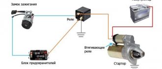
1 - starter; 2 - relay; 3 — ignition switch; 4 - battery
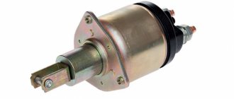
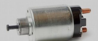
As a device for starting the power unit in the VAZ 2107, a four-brush DC electric starter of the ST-221 type is used. Its circuit does not have protection in the form of a fuse, but it provides two relays: an auxiliary (power supply) and a retractor, which ensures the coupling of the device shaft with the flywheel. The first relay (type 113.3747–10) is located on the engine panel of the machine. The solenoid relay is mounted directly on the starter housing.
The ST-221 starter is installed in the VAZ 2107
The engine start is controlled using the ignition switch located on the steering block. It has four positions, by moving the key to which we have the opportunity to turn on the circuits of various electrical equipment:
- “0” – a position in which all electrical devices are turned off, with the exception of the sound signal, cigarette lighter, interior lamp, and sometimes the radio (depending on how it is connected);
- “III” – exterior headlight lamps, windshield washer and wipers are powered;
- “I” – power is supplied to the ignition system, to the instrument panel, warning lamps and heater fan;
- “II” – current is supplied to the starter relay, retractor and starter field windings.
The engine starts as follows. When the key is turned to position “II,” the corresponding contacts of the ignition switch are closed, and current flows to the terminals of the auxiliary relay, starting the electromagnet. When its contacts also close, power is supplied to the windings of the retractor. At the same time, voltage goes to the starter. When the retractor relay is activated, the rotating shaft of the starting device engages with the flywheel crown and through it transmits torque to the crankshaft.
Using the lock, various circuits of the machine's on-board network are switched on
When we release the ignition key, it independently returns from position “II” to position “I”, and the current stops supplying the auxiliary relay. This opens the starter circuit and turns it off.
Video: if the starter does not turn
Ignition system
The ignition system is designed for timely ignition of the combustible mixture in the combustion chambers of the power plant. Until 1989 inclusive, the VAZ 2107 was equipped with a contact type ignition. Its design was:
- a coil representing a voltage-increasing transformer;
- distributor with contact breaker;
- high voltage wires;
- candles.
1 - generator; 2 — ignition switch; 3 - distributor; 4 - breaker; 5 — candles; 6 - coil; 7 - battery
The ignition coil is used to increase the voltage coming from the battery. The classic (contact) ignition system used a two-winding coil type B-117A, and the contactless one used 27.3705. Structurally they are no different. The difference between them lies only in the characteristics of the windings.
Video: repair of the ignition system of the VAZ 2107 (part 1)
The distributor is necessary to interrupt the current and distribute voltage pulses across the spark plugs. In the "sevens" distributors of type 30.3706 and 30.3706–01 were installed.
By means of high-voltage wires, high-voltage current is transmitted from the contacts of the distributor cap to the spark plugs. The main requirement for wires is the integrity of the conductor and insulation.
Spark plugs produce a spark at their electrodes. The quality and time of the fuel combustion process directly depends on its size and power. From the factory, VAZ 2107 engines were equipped with spark plugs of type A-17 DV, A-17 DVR or FE-65PR with an interelectrode gap of 0.7–0.8 mm.
The contact ignition system worked as follows. When the ignition was turned on, the voltage from the battery went to the coil, where it increased several thousand times and followed the contacts of the breaker located in the ignition distributor housing. Due to the rotation of the eccentric on the distributor shaft, the contacts closed and opened, creating voltage pulses. In this form, the current entered the distributor slider, which “carried” it across the contacts of the cover. These contacts were connected to the central electrodes of the spark plugs via high voltage wires. This is the path the voltage passed from the battery to the spark plugs.
After 1989, the “Seven” began to be equipped with a contactless ignition system. This was due to the fact that the breaker contacts constantly burned and became unusable after five to eight thousand kilometers. In addition, drivers often had to adjust the size of the gap between them, as it constantly got lost.
The contactless ignition system uses a switch instead of a breaker
The new ignition system no longer had any distributor. Instead, a Hall sensor and an electronic switch appeared in the circuit. The operating principle of the system has changed. The sensor read the number of revolutions of the crankshaft and transmitted an electronic signal to the commutator, which, in turn, generated a low voltage pulse and sent it to the coil. There, the voltage was increased and supplied to the distributor cap, and from there, according to the old scheme, it was supplied to the spark plugs.
Video: repair of the ignition system of the VAZ 2107 (part 2)
In the injection-powered "sevens" everything is much more modern. Here in the ignition system there are no mechanical components at all, and the role of the ignition coil is played by a special module. The operation of the module is controlled by an electronic unit, which receives information from several sensors and, based on it, generates an electrical impulse. Then it transmits it to the module, where the pulse voltage increases and is transmitted through high-voltage wires to the spark plugs.
In injection VAZ 2107, the electrical impulse is generated by the ECU
System of external, internal lighting and light signaling
The vehicle lighting and alarm system is designed to illuminate the interior of the cabin, the road surface in the front and rear of the car in the dark or in conditions of limited visibility, as well as warn other road users about the direction of the maneuver by giving light signals. The system design includes:
- front block headlights;
- turn signal indicators (side indicators);
- rear lights;
- salon lamp.
The lighting system includes front and rear headlights, turn signal indicators, and interior lamp
VAZ 2107 was equipped with two front block headlights, each of which combined high and low beam headlights, side lights and direction indicators in its design. Far and near lighting in them is provided by one double-filament halogen lamp type AG-60/55, the operation of which is controlled by a switch located on the steering column on the left. The turn signal unit contains a lamp of type A12–21. It turns on when you move the same switch up or down. The side light is provided by A12-4 type lamps. They light up when you press the exterior lighting switch. The turn signal also uses A12-4 lamps.
The rear lights of the “seven” are divided into four sections:
- direction indicator (lamp A12–21–3);
- side light (A12–4);
- fog light (A12–21–3);
- reversing lights (A12–21–3).
The rear fog lights light up when you press the button to turn them on, which is located on the center console of the car. The reversing headlights turn on automatically when you engage reverse gear. A special “frog” switch installed in the rear of the gearbox is responsible for their operation.
The interior of the car is illuminated using a special lamp located on the ceiling. Its lamp turns on when the side lights are turned on. In addition, its connection diagram includes door limit switches. Thus, the lamp starts to glow when the side lights are turned on and at least one of the doors is open.
The lampshade is designated number 64
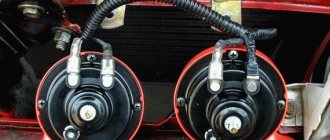
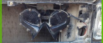
Sound alarm system
The sound alarm system is designed to provide a sound signal to other road users. Its design is very simple, and consists of two electric sound signals (one high-pitched, the other low), relay R-3, fuse F-7 and a power button. The sound alarm system is constantly connected to the on-board network, so it works even when the key is pulled out of the ignition switch. It is turned on by pressing a button located on the steering wheel.
1 - high and low tone signals; 2 — mounting block; 3 - power button
The sound sources in the “sevens” are signals like 906.3747–30. Each of them has a trim screw to adjust the tone. The design of the signals is non-separable, therefore, if they fail, they must be replaced.
Video: repair of the VAZ 2107 sound signal
Additional electrical equipment for VAZ 2107
Additional electrical equipment of the “seven” include:
- electric motors of the windshield wiper gear motor;
- windshield washer pump electric motor;
- cigarette lighter;
- heater fan motor;
- radiator cooling fan electric motor;
- watch.
Windshield wiper motors drive a trapezoid, which in turn moves the windshield wipers across the car's windshield. They are installed in the rear of the engine compartment, immediately behind the engine shield of the car. The VAZ 2107 uses gearmotors of type 2103–3730000. Power is supplied to the circuit when the right steering column switch is moved.
The washer motor drives the washer pump, which supplies water to the washer line. In the "sevens" the motor is part of the design of the pump built into the tank lid. Part number 2121–5208009. The washer motor is activated by pressing the right steering wheel switch (towards you).
1 — electric motors of the windshield wiper; 2 — washer motor; 3 — mounting block; 4 — ignition switch; 5 - washer switch
The cigarette lighter, first of all, is not used to allow the driver to light a cigarette from it, but to connect external electrical equipment: a compressor, navigator, DVR, etc.
The cigarette lighter connection diagram consists of only two elements: the device itself and fuse F-6. Switching on is carried out by pressing the button located at the top of it.
The cigarette lighter is connected to the on-board network via a fuse without a relay
The heater fan electric motor is used to force air into the vehicle interior. It is installed inside the heating unit. The device catalog number is 2101–8101080. The electric motor can operate in two speed modes. The fan is turned on with a three-position button located on the dashboard.
The electric motor of the radiator cooling fan is used for forced air flow of the main heat exchanger of the vehicle when the coolant temperature exceeds the permissible values. Its connection diagrams for carburetor and injection “sevens” are different. In the first case, it is turned on by a signal from a sensor installed in the radiator. When the coolant is heated to a certain temperature, its contacts close and voltage begins to flow into the circuit. The circuit is protected by relay R-4 and fuse F-7.
1 — fan electric motor; 2 - sensor; 3 — mounting block; 4 - ignition relay; 5 - ignition switch
In the injection VAZ 2107, the scheme is different. Here the sensor is installed not in the radiator, but in the cooling system pipe. Moreover, it does not close the fan contacts, but simply transmits data on the refrigerant temperature to the electronic control unit. The ECU uses this data to calculate most commands related to engine operation, incl. and to turn on the radiator fan motor.
In injection "sevens" the electric radiator fan is turned on by a signal from the ECU
The clock is installed inside the car on the dashboard. Their role is to show the time correctly. They have an electromechanical design and are powered by the machine's on-board network.
The clock is constantly connected to the on-board network
Engine management system
Only injection power units are equipped with a control system. Its main tasks are collecting information about the operating modes of various systems, mechanisms and engine components, processing them, generating and sending appropriate commands to control devices. The system design includes an electronic unit, injectors and a number of sensors.
The ECU is a kind of computer in which a program is installed to control the operation of the engine. It has two types of memory: permanent and operational. The computer program and engine parameters are stored in permanent memory. The ECU controls the operation of the power unit, checking the serviceability of all components of the system. If a breakdown is detected, it switches the engine to emergency mode and gives a signal to the driver by turning on the “CHEK” lamp on the instrument panel. The RAM contains current data received from sensors.
The injectors are designed to supply gasoline to the intake manifold under pressure. They spray it and inject it into the receiver, where a flammable mixture is formed. At the heart of the design of each of the nozzles is an electromagnet that opens and closes the nozzle of the device. The operation of the electromagnet is controlled by the ECU. It sends electrical impulses at a specific frequency, causing the electromagnet to turn on and off.
The control system includes the following sensors:
- Throttle position sensor. It determines the position of the damper relative to its axis. Structurally, the device is a variable resistor that changes resistance depending on the angle of rotation of the damper.
- Speed sensor. This element of the system is installed in the speedometer drive housing. A speedometer cable is connected to it, from which it receives information and transmits it to the electronic unit. The ECU calculates the speed of the car based on its impulses.
- Refrigerant temperature sensor. As already mentioned, this device serves to determine the degree of heating of the refrigerant that circulates in the cooling system.
- Crankshaft position sensor. It generates signals about the position of the shaft at a certain point in time. This data is necessary for the computer to synchronize its operation with the cycles of the power plant. The device is installed in the camshaft drive cover.
- Oxygen concentration sensor. Serves to determine the amount of oxygen in exhaust gases. Based on this information, the ECU calculates the proportions of fuel and air to form the optimal combustible mixture. It is installed in the intake area immediately behind the exhaust manifold.
- Mass air flow sensor.
This device is designed to calculate the volume of air entering the intake manifold. The ECU also needs such data to correctly form the fuel-air mixture. The device is built into the air duct. The operation of all systems and mechanisms is controlled by the ECU
Information sensors
The information sensors of the VAZ 2107 include an emergency oil pressure sensor and a fuel level indicator. These devices are not part of the engine management system, since the engine can work well without them.
The emergency oil pressure sensor is designed to determine the pressure in the lubrication system and promptly notify the driver when it drops to critical levels. It is installed in the engine cylinder block and connected to a warning lamp located on the instrument panel.
The fuel level sensor (FLS) is used to determine the volume of fuel in the tank, as well as warn the driver that it is running low. The sensor is installed in the gas tank itself. It is a variable resistor, the slider of which is attached to the float. The fuel level sensor is connected to a gauge located on the instrument panel and a warning lamp located there.
Sensors are connected to instruments and warning lamps
Is the design of the “seven” starter complicated?
The starter is responsible for starting the engine. This is an electric motor with 4 poles and the same number of brushes. It is located in the lower part of the engine compartment on the right side of the cylinder block, as shown in the photo from under the hood. Fixation on the clutch housing is carried out using three bolted connections.
This element is not designed for long-term operation; its only function is to provide the engine with the required torque. Having completed the task, the part returns to a state of rest. So any major fault will result in vehicle failure. The design of the VAZ 2107 starters and other models of this line is the same. If there are some differences, they are insignificant.
It is important to know that the starter can be geared, then the circuit will be a little more complicated, but for the issue under consideration we will not touch on this.
The starter device includes more than 40 small elements from which the main parts are assembled - a DC electric motor, a bendix and a traction relay. They are easy to find in the photo. The functions of the motor include transmitting torque to the crankshaft through a gear transmission. Thanks to the retractor relay, the movement of the bendix is ensured. In addition, the relay is also responsible for closing the contacts of the electric motor. Bendix is a small part, but it performs a very important task - it ensures coupling between the shaft and the flywheel crown. And only after this is it possible to rotate the crankshaft.
Starter VAZ 7 models (from 01 to 07)
The commutator-type electric motor used to start the engine is located on the side of the crankcase of the power unit. The parts are connected to each other by bolts with a hexagonal head. Power is supplied from the battery.
The power of the device is sufficient to rotate the crankshaft at air temperatures down to -35 ° C (without preheating the oil). The appearance and design of the device are shown in the photo in the spare parts catalogues.
Removing the starter and protective screen
To repair the starter, it must be removed from the car. If the car is relatively new and the starter has not yet been removed, then the heat-reflecting protective screen is in its rightful place. It will prevent you from removing the starter, so you need to remove it first.
The protective screen is attached on top to two studs with 13 nuts and on the bottom with a 10 head bolt. And if the nuts can be unscrewed with a simple wrench, then to unscrew it you will need a long thin socket wrench. Many, having removed the protection, do not put it back in place, but it is better to do it anyway. Without it, the starter gets very hot from the exhaust manifold, especially in summer in traffic jams.
Starter guard and bottom bolt location
Purpose
The device is designed to force the engine crankshaft at startup. The product is equipped with a special Bendix clutch, which engages with a ring gear mounted on the flywheel of the power plant. The electric motor is controlled remotely using a contact group in the ignition switch through an additional relay.
Starter electrical connection diagram
There are 2 types of electric motors for starting the power plant:
- On cars with a carburetor, a standard starter is used; torque is transmitted directly from the rotor to the ring gear.
- On some carburetor cars and VAZ 07 with an injector, a gear type drive was installed. By using a planetary gear, the current in the power circuit is reduced and the torque is increased.
How does the starter start the engine?
Let's take a closer look at the principle of operation of the starter. After closing the contacts, the current flows to the winding of the traction relay. At this time, the anchor moves and extends the bendix. The gear of the latter is connected to the flywheel ring. When the armature reaches its final position, the contacts close, allowing current to flow to the starter motor winding. The device begins to rotate and the car starts.
The Bendix returns to its original position as soon as the flywheel begins to rotate at a higher speed than the starter shaft. And the supply of electrical energy to the device stops when the key returns to the first position. A gear starter is also installed on the VAZ 2107, in this case the current flow pattern is slightly different; it reaches the armature through a gear drive. Thanks to this, power is significantly increased. This is not the only difference that the gear mechanism has, but we won’t talk about that now.
This is interesting: The consequences of pressing the start/stop button while the car is moving
Starter activation relay
When the starter clicks and does not turn, and a cracking noise is heard from the relay, then the fault may concern the control cable that powers the relay or the relay itself. In such a case, the power unit can be started by shorting the positive from the battery to the positive terminal of the relay.
Thanks to this starting method, the starter works, then you can be sure that the problem does not concern the battery. Most often the relay, ignition switch, and wiring are to blame.
Where is
The engineers provided for the location of the relay under the right side of the hood, or rather near the right wing of the car. It is mounted on a stud with a nut.
Examination
If the starter relay clicks, then you should first check its functionality. You must use a special “control” or voltmeter. The work is done as follows:
- It is necessary to remove the wire block from the relay.
- Check the contacts in the block and relay to see if they are oxidized. If yes, then clean them thoroughly.
- Check the ground on the relay going to contact number 86.
- Also check the voltage in wire 85, which goes to the relay, when you want to try to start the car with the key. You also need to check wire number 30.
- If the wires conduct current, then the problem is not the power supply.
Connection diagram and possible difficulties
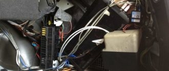
To prevent a starter failure from taking you by surprise, let’s look at how to replace it yourself. But before we talk directly about connecting the VAZ 2107 starter, you should find out how to dismantle the old element. The only problem you will encounter is the inconvenient location of the part; both carburetor and injection models suffer from this.
We install the car above the inspection hole, since the unit can only be reached through the bottom. Be sure to turn off the ignition. Then remove the battery cover and disconnect the ground terminal. To free access, the battery must be removed, and we do this together with the support. It's time to unscrew the wire harness clamp and remove them from the traction relay. And the last operation is to unscrew the bolted connections securing the part.
Next, we are interested in the connection diagram for the starter on the VAZ 2107. Having installed the new element in its regular place, we screw the longest bolt first, and then we fix the remaining fasteners. We install back the wire terminals, harness supports and battery. We connect the battery and do not forget to replace the protective cover and the dirt shield.
For non-carburetor models, some inconvenience may arise during installation, so when replacing a VAZ 2107 injection-type starter, it would be useful for the owner to remove the inlet pipe extension.
With careful attention and no haste, this entire operation is unlikely to pose any complications, so even an inexperienced car owner will be able to handle the replacement process. The scheme is already known, and for clarity, we tried to duplicate all the steps with photographic materials; now everyone can change the starter on a VAZ 2107. The main thing is to choose the right mechanism for your car, and the principle of operation can be either conventional or geared; when replacing, many do not miss the opportunity to acquire a more complex but effective mechanism.
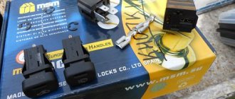
Connecting wires to the starter
Connecting a starter to a VAZ - instructions. Attach the relay in a convenient place (for example, a washer reservoir). Connect the wires to the starter. Then remove the red wire located on the flat terminal of the relay, and you need to make a connection with the connector of the male wire and the wire from the new relay.
Place the wire with a ring terminal for 8 mm on the positive side of the starter and tighten it with a nut. Place the wire of the new “female” type relay onto the contact that was released at the traction relay. This wire will transmit the positive to the coil. Using a clamp, tighten the new wire and the stock one together. Screw a small length of wire from the coil. Now you can turn on the new relay.
VAZ 2107 starter repair
The engine is started on a modern car using an electric starter. Failure of this device can occur for various reasons related to its defects or natural wear and tear of the unit. Repairing a VAZ 2107 starter makes sense only if the cost of spare parts and labor does not exceed the price of a new one. In any case, first you need to establish the causes of the malfunction; this can be done by analyzing their external manifestations:
- Idle rotation of the rotor indicates a breakdown of the overrunning clutch.
- Clicks of the solenoid relay in the complete absence of other signs of starter operation indicate burnt contacts.
- Lack of rotation of the starter rotor can be caused by wear of the brush assembly or a break in its winding.
In some cases, unsuccessful attempts to start the engine are due to a low battery charge. Drivers usually face this problem in winter. Starter repair begins with its removal, cleaning of contaminants and a thorough inspection.
What if the flywheel crown is worn out?
If the crown has been ordered to live for a long time, then this can be felt in the literal sense of the word after removing the starter. Run your hand over the teeth and assess the degree of wear. If you need to change the crown, this is done after removing the gearbox. Carefully knock off the old crown from the flywheel. If it is being removed for the first time, then you can cheat a little and put it on the other side. The teeth are only half worn, so you can reuse the part to save money. This will save you 300-400 rubles, but if you want to install a new crown, do it. The new one is still stronger than the old one.
But you will have to warm it up on gas for several minutes; there are no other ways to install it on the flywheel. Carefully put the crown on, press it and wait a few seconds for the metal to cool and press the flywheel tightly. There is no point in removing the latter; everything can be done quickly enough if you have an inspection hole or overpass. After the work has been completed, check the operation of the starting mechanism; the starter should not feel any obstacles when rotating the rotor.
Source
Dismantling the unit
To perform this operation, you need a set of wrenches and a portable lamp to illuminate the work area. The procedure for dismantling the starter is as follows:
- Disconnect the battery.
- On the solenoid relay, unscrew the nut on the contact pin and remove the wire connecting it to the battery.
- Turn off the control circuit.
- Using a key set to “13”, unscrew the three bolts securing the starter to the cylinder block.
- Carefully remove the device from its seat and, unfolding it, remove it from the engine compartment.
When dismantling the device, be careful not to damage nearby wiring.
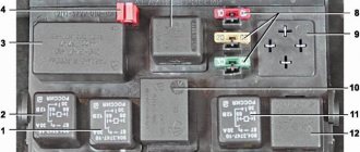
Explanation of symbols
The wiring diagram contains the following symbols:
- 1 – radiator fan drive motor;
- 2 – mounting block block;
- 3 — idle speed sensor;
- 4 – engine ECU;
- 5 – potentiometer;
- 6 – set of spark plugs;
- 7 – ignition control unit;
- 8 – electronic crankshaft position sensor;
- 9 – electric fuel pump;
- 10 – indicator of the number of revolutions;
- 11 – lamp for monitoring the health of electronic systems and the brake system;
- 12 – ignition system control relay;
- 13 – speedometer sensor;
- 14 – special factory connector for reading errors using the BC;
- 15 – injector harness;
- 16 – adsorber solenoid valve;
- 17, 18, 19,20 – fuse box for repairing the mounting block that protects the injection system circuits;
- 21 – electronic fuel pump control relay;
- 22 – electronic relay for controlling the exhaust manifold heating system;
- 23 – exhaust manifold heating system;
- 24 – fuse protecting the heater circuit;
- 25 – electronic air sensor;
- 26 – coolant temperature control sensor;
- 27 – electronic air damper sensor;
- 28 – air temperature sensor;
- 29 – pressure control sensor and low oil pressure lamp.
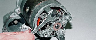
Diagnosis of faults and disassembly of the mechanism
The starter, removed from the engine compartment, must be cleaned of dirt and traces of technical fluids. The procedure for disassembling the mechanism is as follows:
- We remove the solenoid relay from the starter housing and, having unscrewed the tightening screws, disassemble it into its component parts. During the inspection, special attention is paid to brass contact groups, the burning of which can lead to failure of the mechanism.
- We remove the cover of the device and check the condition of the brush assembly. Significant wear on the tracks and wear of carbon parts is a common cause of starter failure.
- The integrity of the rotor winding is checked using a multimeter set to resistance measurement mode.
- The overrunning clutch is checked by hand; a working device allows only one-way rotation.
After establishing the cause of the failure of the electric starter, you should take care of purchasing the necessary spare parts.
Starter malfunction
If a click is heard after turning the ignition key, but the engine does not start, then, as a rule, the cause of the breakdown is the unit itself. If one click is heard, then the charge required for ignition is reached, since the relay clicked. So the problem is not with him. The cause may also be an unstable charge, which is not enough to ignite.
In such a case, it is advisable to try to start the car several times at intervals of half a minute. Sometimes this helps, but if the issue is not resolved, then you need to check the elements for malfunction:
- bendix;
- retractor unit;
- winding for open circuit;
- check if the winding is short-circuited;
- The bushings and brushes were worn out (then you just need to replace these elements).
VAZ 2114 starter – connection diagram, device, technical characteristics
The starter installed on the VAZ model we are interested in is type 5712.3708.
The device is excited by permanent magnets. Its rated power is 1.55 kW and the current is:
- up to 700 A in the inhibited state;
- up to 375 A at maximum power;
- up to 80 A at idle.
The starter devices and its operation diagram are as follows:
- four permanent magnets are placed in the stator (in its housing);
- liners made of metal-ceramic material are mounted in the support and cover, in which the rotation of the armature shaft is carried out;
- the planetary gearbox imparts movement to the drive shaft from the armature shaft;
- the front end of the drive shaft rotates in a cermet bushing, which is built into the clutch housing;
- The movement of planetary gears occurs on needle-type bearings;
- when the device we are considering is turned on, the voltage from the battery is supplied through the ignition switch to the windings (there are two of them) of the traction relay, and after its contacts close, the retractor winding is switched off.
What is the design of the gear-six starter?
The VAZ 2106, produced after the 1980s, has a starter with an end manifold model 35.3708. Earlier cars from the Volzhsky plant had a different gear mechanism installed - ST-221, which was equipped with a cylindrical manifold. Their structure is approximately the same, so they are completely interchangeable.
Let's take a closer look at the design of the mechanisms that interest us, using model 35.3708 as an example. The “six” gear starter consists of the following main parts:
- field winding (i.e. stator) and housing;
- electric drive with anchor;
- three special covers;
- electromagnetic traction relay with two windings (one of them is retracting, the other is holding).
Using bolts, the starter housing is secured into one block with three covers. The armature of the mechanism we are interested in has a core, a commutator and a shaft. The last of these elements rotates in metal-ceramic bushings (there are two of them structurally provided). These bushings are pressed into the covers and must be impregnated with a lubricant. The starter drive is located at the end of the shaft. It includes a gear and a roller clutch, which is necessary to transmit torque to the flywheel.
On the front cover there is a relay consisting of a yoke, several flanges and a core. When the gear mechanism is turned on, two processes occur simultaneously: the armature is retracted, and the drive and gear mesh with the flywheel; a special contact plate closes the bolts. The result of these processes is the start of power supply to the windings of the device we are considering. As you can see, the circuit for switching on and operating the “six” starter is quite simple.
Is the starter spinning poorly?
Let's start with the fact that it may simply not have enough current. This may be due to insufficient battery charge. But more often, of course, the problem lies in the wiring
Pay attention to the thick wire that goes from the negative terminal of the battery to the engine block. There is also a cable that connects the internal combustion engine to the gearbox
If a lot of dirt and oil has accumulated on them, then there is clearly a large current leakage. Basic electronics, nothing fancy, look at the starter wiring diagram to make sure it's dead simple. So what can you do to reduce current leakage?
And here are the contacts of the retractor relay shown
The sequence of actions is as follows:
- Clean the contacts with sandpaper.
- Wash with solvent or WD-40.
- Restore lost contact.
But if the starter still turns “forcefully”, slowly, and doesn’t even try to accelerate, then change all the ground wires. Only this can really help. The problem is that the ground wires are made of thin wire, which is woven into a large bundle. Dirt and dust accumulate between the wiring, hence, again, large current leaks. And restoring the wires turns out to be very problematic.
We repair the starter on a car with an injection engine
- We remove the mudguards, both main and additional. This action is impossible if you do not have a socket wrench size 8. Using it, you need to unscrew 4 screws that are located on the main panel, or rather, on its side and front fastenings, as well as 2 bolts located on the additional one. There is also a lower screw, but it has a different diameter. To remove it you will need a 10 mm socket wrench.
- Now, using a long 13mm socket wrench, unscrew the bolts that secure the clutch housing and starter. After this, unscrew the bolts with which the starter is attached directly to the bracket and the inlet pipe extension.
- We remove the stretch marks of the intake pipeline and very carefully, using the same wrench, unscrew the exhaust manifold nut, and then remove the shield.
- We disconnect the wire that we have left from the battery terminal and remove the tip located on the contact rod.
- The traction relay output must be freed from wire 50, and then the starter itself must be removed. Now it can be disassembled. Before doing this, try to thoroughly clean the part to remove any dirt stuck to it.
Once the starter is in your hands, the procedure is as follows (by the way, it is absolutely identical for any type of engine of the above car):
- check the solenoid relay. After connecting the 50th relay output to the “plus” terminal of the battery, we connect the starter housing directly to the “minus” terminal. This way, it will become clear whether the problem is in the relay itself or is it in something else. If it is in working condition, then a distinct click will be heard during this action;
- To check the integrity of the windings, you need to get rid of the starter cover and disconnect the brush assembly. Using an ohmmeter, check whether there is a short to the starter housing;
- if the results of our test showed that the relay still works, we take out the anchor. To do this, unscrew the bolts securing the starter casing, remove the lock washer, as well as the gaskets. Then unscrew the two nuts and completely remove the back cover. Thus, the starter winding housing is freed from the studs;
- unscrew the nut of the eccentric rotation axis and remove it from the body, disconnecting the armature.
At this point, the process of disassembling the starter can be considered complete. The anchor, by the way, cannot be repaired, but it can easily be replaced with a new one. Reassembling the starter is carried out in the reverse order.
VAZ 2106 starter - how is it removed and replaced?
The scheme for dismantling the old device and connecting a new one does not require special forces from the car enthusiast. Anyone who is “armed” with the necessary tools (screwdrivers, a mandrel, several keys - 10, 8 and 13, a hammer, pliers), will be able to remove the gear starter and will carefully watch the video of this process (for many car enthusiasts it is enough to study the photo of the operation so that the disassembly of the mechanism will be “ without a hitch").
The diagram for such disassembly and connection of a working device is elementary. First, the air filter (or rather its housing) is removed. To do this, you need to use a 13mm wrench. Use it to disconnect all three bolts that secure the filter to the gearbox housing. After this, the wires are pulled away from the starter and dismantled. Now you can begin disassembling the mechanism in the following sequence:
- remove the relay (use a 13 key again to remove the washers and wires from it);
- dismantle the starter casing (unscrew the mounting screws);
- Using two screwdrivers, we carefully “squeeze” under the retaining ring equipped with a washer and remove it;
- We disconnect the bolts that hold the body and cover together using a 10mm wrench, and then unscrew the screws of the windings and connecting cable.
All that remains is to knock out the rear bearing (use a mandrel), remove the cotter pin (pliers), the rubber plug and the bendix. Install a new mechanism - the replacement of the starter was successful!
Home →
Maintenance and Repair → Repair →
Dismantling and replacement
To make it more convenient to replace the relay, it is recommended not to be lazy and still remove the starter itself. This will allow you to simultaneously check the condition of the starter while replacing the relay.
The removal procedure described below concerns an assembled relay, which has the ability to replace individual structural elements.
- Disconnect the negative terminal from the battery.
- Disconnect the red terminal from the relay. This is a red wire.
- Using an 8 mm wrench, unscrew the nut securing the brush assembly. You will find it behind the relay.
- Remove the contact that this nut held in place.
- Unscrew the fastening of the solenoid relay to ground. We are talking about coupling bolts.
- Next, you need to dismantle the power wire, after which the relay itself is pulled out.
- The fastening nuts are unscrewed from the end part, which allows you to remove the upper part of the relay.
- It is advisable to immediately replace the relay core with a new one.
- Install a new relay.
- Proceeding strictly in reverse order, reassemble the assembly, which will allow you to complete the replacement of the unit.
- When separating the relay into its two component parts, be sure to ensure that the core does not slip out and the spring does not jump out.
We can say that replacing the gearbox on a VAZ 2114 is not so difficult. It is much easier to replace a non-separable relay, since to replace it it is enough to unscrew all the fasteners in the same way and disconnect the contacts.