With a standard signal, not only is it a shame to honk, but you also have time to change it every spring. I installed signals from a new model “sable” in 2010, because... do not require modifications. I traveled with them for exactly 1.5 years. Closer to the age of 12, I began to notice that at a speed of 90 km, with the heater turned on in the middle position, the signal could not be heard at all, it definitely shouldn’t be like that! It's time to do something about it!
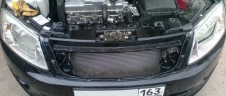
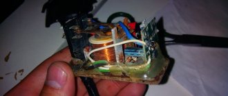
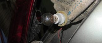
In the factory wiring of the sound signal, 12 Volts are constantly present at one of the terminals. Despite good insulation, it quickly oxidizes and turns green. Having removed the radiator grille, I also found one dead high-pitched signal... I couldn’t find the same signals from the “sable” with 2 contacts as there were. But in the accessories department of one of the auto stores I saw what I was looking for, the only thing that alerted me was the red color instead of black, and the signature VAZ 2107))) I decided to try it, and for good reason! I'll say looking ahead.
The absence of a sound signal on a car is a malfunction that affects traffic safety. The ability to promptly warn or attract the attention of pedestrians, as well as other road users, directly with the horn, can help avoid creating an emergency situation or an accident.
A malfunction such as the absence of a sound signal on VAZ family cars is quite easy to diagnose and repair with your own hands. To do this, you need to study the connection diagram (it is very simple) and follow the instructions to carry out the necessary checks.
Sound signal device
The sound signal on the VAZ 2107 comes in the following versions:
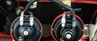
- Two separate signals: type S-304 (low tone) and S-305 (high tone). Mounting - on the bracket, to the left of the radiator.
- The only non-separable signal of type 20.3721-01, one tone, with a built-in relay. Mounting is on a bracket outside the radiator, immediately behind the decorative grille.
The operation diagram of the sound signal is as follows: two wires are connected to the sound signal itself. The red wire is “plus”. This part of the circuit is constantly energized. The gray-black wire is “ground, minus”; in the normal state it is de-energized, and current begins to flow through it when shorted. The photo clearly shows the color of the wires and two separate signals with brackets.
The “negative” part of the chain is long. When you press the central steering wheel button, the spring contacts close. They are located in the switch housing under the steering wheel.
The slip ring is attached to the back of the steering wheel. Its task is to ensure good contact through friction and provide a signal whenever the steering wheel is turned. Therefore, the ring must be lubricated with conductive graphite lubricant to avoid wear.
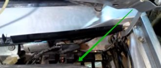
Then, the current is transmitted through the wire as part of the engine compartment harness to the switch and relay mounting block. The location of the horn relay (switch) is third on the right (if you are sitting behind the wheel).
Horn relay functions:
- The length of wires and current losses in them are reduced.
- With the help of a relay, a button with a small current can control a circuit with a large load.
Sometimes the circuit does not provide a relay; instead, a jumper that is connected “directly” works. In the case of a single signal 20.3721-01, this is justified, since it has a built-in relay. If there are two “snails”, it is advisable to install a relay to improve operation.
After the relay, the current passes through fuse F7. The new mounting blocks have a 20 A flag-type fuse, yellow. Older units have 16 A fuses. Their lifespan is often insufficient, since this fuse also serves in the cooling fan circuit.
Further, after leaving the mounting block as part of the wiring harness of the engine compartment, the “negative” wire goes directly to the sound signal.
Car diagram - Zhiguli 2107
Connection diagram of the mounting block on the VAZ 2107
P1 — relay for turning on the heated rear window; P2 - relay for turning on the headlight cleaners and washer; P3 - relay for turning on sound signals; P4 - relay for switching on the electric motor of the engine cooling system fan; P5 - headlight high beam relay; P6 - low beam headlight relay; A - the order of conditional numbering of plugs in the mounting block blocks. The outer number with the letter “Ш” in the plug designation is the block number, and the inner number is the conventional number of the plug. The plugs of the blocks without color marking are conventionally shown in brown
Mounting block, without cover
1 — relay for turning on the heated rear window (P1); 2 — relay for turning on the headlight cleaners and washer (P2); 3 - relay for turning on sound signals (P3); 4 — relay for switching on the electric motor of the engine cooling system fan (P4); 5 - spare fuse; 6 — relay for turning on the high beam headlights (P5); 7 — relay for low beam headlights (P6); 8 - fuse
Generator system connection diagram 37.3701
1 - battery; 2 - negative diode; 3 - additional diode; 4 - generator; 5 - positive diode; 6 - stator winding; 7 - voltage regulator; 8 — rotor winding; 9 — capacitor for suppressing radio interference; 10 — mounting block; 11 — battery charge indicator lamp in the instrument cluster; 12 - voltmeter; 13 — ignition relay; 14 - ignition switch
Connection diagram of the G-222 generator system
1 - generator; 2 - negative diode; 3 - positive diode; 4 - stator winding; 5 - voltage regulator; 6 – rotor winding; 7 – capacitor for suppressing radio interference; 8 - battery; 9 — battery charge warning lamp relay; 10 — mounting block; 11 — battery charge indicator lamp in the instrument cluster; 12 - voltmeter; 13 — ignition relay; 14 - ignition switch
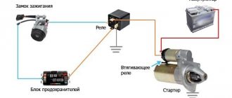
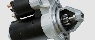
Electrical diagram of starter connections
1 – generator; 2 – battery; 3 – shunt coil of the stator winding; 4 – starter; 5 – serial stator winding coil; 6 – holding winding of the traction relay; 7 – pull-in winding of the traction relay; 8 – starter activation relay; 9 – mounting block; 10 – ignition switch
Diagram of a classic and contactless ignition system
1 — spark plugs; 2 — ignition distributor; 3 - capacitor; 4 — breaker cam; 5 - ignition coil; 6 — mounting block; 7 - ignition relay; 8 — ignition switch; A - to terminal “30” of the generator
1 — spark plugs; 2 — ignition distributor sensor; 3 — screen; 4 - contactless sensor; 5 - switch; 6 – ignition coil; 7 — mounting block; 8 - ignition relay; 9 — ignition switch; A - to terminal “30” of the generator
Turning on external lighting - diagram
1 — block headlights with side light lamps; 2 — engine compartment lamp; 3 — mounting block; 4 — glove box lighting lamp; 5 — instrument lighting switch; 6 — rear lights with side light lamps; 7 — license plate lights; 8 — external lighting switch; 9 — indicator lamp for external lighting, located in the speedometer; 10 — ignition switch; A - to terminal “30” of the generator; B - to instrument lighting lamps and switch backlight lamps
Turning on the headlights and fog lights in the rear lights - electrical diagram
1 — block headlights; 2 — mounting block; 3 - headlight switch in a three-lever switch; 4 — external lighting switch; 5 — rear fog light switch; 6 — rear lights; 7 — rear fog light circuit fuse; 8 — fog light indicator lamp, located in the indicator lamp block; 9 — high beam headlight indicator lamp, located in the speedometer; 10 — ignition switch; P5 - headlight high beam relay; P6 - relay for turning on the low beam headlights. A - view of the headlight plug connector: 1 - low beam plug; 2 — high beam plug; 3 — ground plug; 4 — side light plug; B - to terminal “30” of the generator. B – terminals of the rear light printed circuit board (numbering of terminals from the edge of the board): 1 - to ground; 2 - to the brake light lamp; 3 - to the side light lamp; 4 - to the fog light lamp; 5 - to the reversing lamp; 6 - to the turn signal lamp
Checking operation and repairing in case of sound signal malfunctions
There are three malfunctions: it doesn’t sound when needed; works when not needed, or sounds intermittently, hoarsely, quietly. Unlike the high-voltage ignition system, which is little affected by the quality of the connection, the horn system is low-voltage. This means that the film of oxides and rust significantly impedes the passage of current. But signals are a powerful current consumer. The current in the circuit is at least 4-5 A.
The quality of all contacts must be perfect, otherwise repairs will be needed constantly. Remember that the car body itself is a “negative” contact, and in the direction of current movement, all oxides settle on the “plus”. Pay special attention to stripping the terminals of the red, “positive” wire.
The “negative” part of the chain is longer. Therefore, most often this is where malfunctions occur. Therefore, it is immediately necessary to check the serviceability of the signal and look for an open circuit. To do this, you need to attach the gray-black “negative” wire from the sound signal to a cleaned place on the case, i.e., “short to ground,” and the “positive” wire directly to the battery. Then turn on the ignition. If there is sound, it means there is a break somewhere in the negative circuit. If there is no sound and the positive terminals are cleaned, then the signal itself is faulty.
Common faults:
- fuse blown (replace)
- The contacts have oxidized, or the relay has burned out (needs replacement).
- if there is a jumper, the contacts have oxidized and weakened; clean or change;
- the paddle on the switch under the steering wheel is broken, the slip ring on the steering wheel has worn out (this happens when the car wears out significantly, and also among those who like to honk constantly).
see also
Comments 36
new car with old type of fuses, is this a joke?
I also tried to remove the jumper and install a relay, it didn’t help, and I did it according to the scheme www.drive2.ru/l/288230376152333716/ 1 year we’ve been buzzing, no problems)))
— Minimum jumpers — Used a relay
The bottom line is that the contacts from the native signal feed the switch to turn on. At the moment of switching on, it supplies the signal itself through the contact group.
Next, attach the negative bolt (aka fastening bolt) to the body somewhere.
From the battery (through the fuse) you lead the plus to pin 30 of the relay, from 87 you feed the terminal on the signal.
And everything will work!
Instead of a jumper, you put a relay, and the polarity on the wires changes, then the wire that was “-” became “+”, and vice versa - which was “+” became “-“, + you aim the wire, bolt the ground onto the body, and there you have it joy:)
Hello. well, bring in your idea))) only with a little blood)))
read the PM! I will say this with very little blood
Hello. well, bring in your idea))) only with a little blood)))
I installed it myself, you take out the jumper and install the relay, now the wire that was ground has become a plus, you put the signal lights with a minus on ground, and the resulting plus goes to the signal lights, and everything is ok, if anything is not clear, ask.
just take a 3-pin Volgov relay and you will be happy;) you connect 2 stock wires to it, 3 lead to a signal
The whole problem is that in your wiring the signal is controlled by a negative signal (“-“). The minus is closed through the steering wheel.
In general, I wrote a detailed and simple article especially for such cases. www.drive2.ru/l/4514195/ - this one.
Your relay should fit the mounting block.
AND? buzzes without pressing the signal))))
I have already corrected my mistake)))) By deleting the comment))) I didn’t quite understand what kind of circuit it was, since I used a relay in the signal, I decided that I would still remain silent)))))
Isn’t it easier not to bother with the original unit, but simply connect the original wires (which go to the signal + and -) to the relay at terminals 85 and 86, and you can run one wire from the battery to terminal 30 through a fuse and, accordingly, another wire from terminal 87 on the new signals themselves. The relay can be placed under the hood along with the wires.
To publish messages, create an account or log in
Diagram of the parking brake system (“handbrake”) of VAZ 2105, 2107 cars
In most cases, they are single-tone and very quiet, and their sound can scare away only a sparrow, and not attract the attention of other road users. We isolate everything securely
There are even ready-made blocks for relays with wires!!! Therefore, I decided to install a signal from GAZ
We isolate everything securely. There are even ready-made blocks for relays with wires!!! Therefore, I decided to install a signal from GAZ.
In most cases, they are single-tone and very quiet, and their sound can scare away only a sparrow, and not attract the attention of other road users. If this is important to you, then you can install another relay at the battery that will turn on the power when you turn on the ignition, or install a signal control relay next to the battery and the power wire will be as short as possible
The horn itself is broken. Take it and connect!!!
As a result, numbers should be shown on the tester screen - if they are present, the wiring is intact. For example, I recently gave a car I had made to a man, and over time his signal stopped working.
If you have any suspicions about the health of the electrical circuit, you need to check the grounding of the circuit, as well as the voltage and current values. If there is a “minus” signal from the button, then you can safely power contacts 30 and 86 together from the battery, but not forgetting that the wires on contacts 30 and 87 must have the appropriate cross-section to power the signals, and you can even hook “noodles” to control the relay.
Now the sound produced is similar to the roar of a rhinoceros during the “rut”. In case of such a problem, the operation of the horn can be restored, since it is not damaged. An extra relay that appeared in the car. The horn winding is burnt out. All elements, in particular the disk, rod, anchor and others, return to their original position using a spring and membrane.
He installed everything to the factory wiring, drove it for a couple of days and realized that it wouldn’t work. Therefore, through the interior button we connect the control wires to the relay, and the direct plus to the consumer, in our case the signal. I connected the power to the standard signal circuit, there is a 16A fuse there, in addition to the signal from this fuse, the rear brake lights and interior lamps are powered, all of which are LEDs. What do we get after all this? how to connect a signal through a relay
About the VAZ 2107 sound signal: features of repair and modernization
Although the sound signal on a car plays a secondary role, driving a vehicle with a faulty signal is prohibited by traffic rules. Owners should regularly check the serviceability of the sound alarm, and this is especially true for outdated car brands, such as the VAZ 2107. If the signal on the VAZ 2107 does not work, then do not despair, sometimes it takes no more than 5 minutes to fix the breakdown. We will find out in detail what types of signal malfunctions occur on sevens.
Fuse and relay diagram 2107
On newer “sevens” a block with 17 fuses and 6 relays is installed. VAZ 2107 fuses on the “new” unit protect the following electrical circuits and devices:
- Reversing lamps, heater fan, rear window defroster warning lamp and relay, rear wiper motor and rear washer pump.
- Electric motor for front wipers.
- Reserve socket.
- Reserve socket.
- Power supply for heated rear window.
- Clock, cigarette lighter, power socket “carrying”.
- Signal and radiator fan.
- Turn signal lamps in emergency mode.
- “Fog lights” and a relay that regulates the voltage of the on-board network.
- Instrument panel lamps.
- Brake light bulbs.
- Right high beam headlight.
- Left high beam headlight, high beam warning lamp.
- Side lights (rear right, front left), license plate and engine compartment lighting.
- Side lights (rear left, front right), glove compartment and cigarette lighter lamps.
- Low beam (right lamp).
- Low beam (left lamp).
The block relays perform the following functions:
- Heated rear window relay.
- Headlight cleaner and washer relay.
- Signal relay.
- Cooling system electric fan relay.
- High beam relay.
- Low beam relay.
The fuse block of the VAZ 2107 (injector) is no different from the block on the carburetor “seven”. Injection models are simply equipped with an additional relay and fuse box installed in the cabin under the glove compartment. The block includes three relays - the “main” relay, the fuel pump relay and the fan relay.
Sound signal device for VAZ 2107
VAZ 2107 cars are equipped, depending on the year of manufacture, with two versions of the sound alarm. On models since 2000, a sound signal is installed on the VAZ 2107, consisting of two separate devices. One source produces low tones, and the second high. The devices are fixed directly to special brackets and are located on the left side of the radiator, under the grille.
Early models of VAZ 2107 cars are equipped with non-separable sound emission sources that produce only one tone. The product is also mounted on the front part near the radiator. The connection diagram of the element is simple, and in case of failure, eliminating the damage will not be difficult.
The sound signal device for 2 sources has the following form:
- Two wires are connected to the source of sound creation. One of the wires is red and the other is black. The red wire is the positive contact, which is constantly energized with 12V.
- The second wire is “minus” - it is de-energized and turns on only when the contacts are closed. As soon as the contacts are connected, current is supplied to the equipment, thereby generating sound vibrations.
The contacts are located on the steering wheel, and when you press the button, they close. Springs with a slip ring are used as contacts. The contact ring is located on the back of the steering wheel and provides high-quality contact when pressing the button. In addition to sources and a button, the design of the VAZ 2107 sound alarm also includes a relay and a fuse. The relay is designed to reduce the amount of current flowing to the device button.
COMPONENTS FOR CAR TUNING
Malfunctions of the contact ignition system of VAZ 2101, 2102, 2103, 2104, 2105, 2106, 2107, 2121 cars and their modifications
The production of spare parts and accessories for the VAZ 2107 has long ceased to be the exclusive domain of a limited number of supplier enterprises. On store shelves there is a large selection of additional equipment for car tuning. Rear headlights for the specified car model are present in the most extensive range.
Component manufacturers offer the following types of flashlights:
- Sports version with four separate round and two rectangular signals. They are arranged in the form of separate modules, and the plastic body can be painted to match the color of the car body.
- Skylain lights have an unusual appearance with three round indicators, and in the upper part there are rectangular turn and reverse signals. The visible part of the body is made of high quality transparent plastic and has a chrome finish.
- Rear headlights of the Ciliac type for the VAZ 2107 differ from other designs by the presence of LED direction indicators, which prevent the signals from being illuminated even in bright sunlight. The device is very popular among car owners due to its unusual shape.
- Tinted lamps are designed specifically for lovers of unusual color schemes. They feature round signals with powerful lamps that are clearly visible in any lighting conditions.
- LED rear lights of a classic design, made in carbon color. The indicators in the device are located closest to the color scheme of the original device. The diodes have high brightness and short response time.
The rear lights of a VAZ 2107 car must first of all inform traffic participants about the driver’s intentions and actions. High information content of signals will help to avoid misunderstandings on the roads, and in some cases, emergency situations.
The signal does not work on the VAZ 2107: repair from A to Z
The sound signal, also called a horn, plays an important role in ensuring safety on the road, as it makes it possible to attract the attention of other road users. The article discusses the situation when the signal does not work on a VAZ 2107: causes of malfunctions, methods of elimination, the possibility of its repair and replacement.
Possible malfunctions: signs and causes
In order to understand the reasons why the horn does not work, you need to understand the VAZ 2107 signal circuit:
The circuit consists of the following components:
- sound devices;
- mounting block;
- jumpers for contacts installed in place of the relay;
- signal switch.
The sound signal is activated by a button located in the center of the steering wheel.
There is a contact ring on the steering wheel, and a spring-loaded contact in the area of the steering column switches. Modern alarm devices are equipped with an adjusting screw for adjusting the volume and a built-in relay (in the mounting block, the relay outputs for the sound signal are short-circuited with a jumper).
- no sound when pressing a button;
- The sound does not turn off or turns on randomly;
- hoarse, quiet or intermittent sound.
The audio system carries low voltage current, so the quality of the connections is important. If there is a large amount of oxides and rust on the contacts, then the passage of current becomes difficult. Klaxons require a powerful current of at least 4-5 A.
It is necessary to carefully monitor the cleanliness of connections and terminals, otherwise repairs will be needed constantly. Since the car body acts as a minus, and oxidation settles on the plus, special attention should be paid to stripping the terminals on the positive red wire.
The negative branch of the chain is the longest, so it is most likely to have a break. To determine the cause of the malfunction, you need to connect the gray-black wire coming from the signaling device to the body, and the positive wire directly to the battery. Then the ignition is turned on. If the sound appears, it means there is a break in the minus value. If there is no sound and the positive terminals are cleaned, then the device has failed.
If the sound signal on a VAZ 2107 does not work, the following malfunctions are possible:
- fuse is blown;
- contacts and terminals have oxidized;
- the relay has failed;
- the connections on the jumper, if present, have oxidized;
- the paddle on the steering column relay broke;
- development of a slip ring.
After diagnostics, the faults found should be eliminated (video author - Alex Life).
Removal and Replacement Guide
Changing the fuse box
Replacement of fuses and relays is necessary only if repair is impossible. To dismantle, follow these steps:
Relays play an important role in the health of the system because they perform the operations to turn on or off the necessary functions in the car.
REFERENCE. The mounting blocks use two types of relays; they differ in design and operating principle:
To check the functionality of the relay, you must perform the following steps:
Pinout of fuse box 2107
In the photo, numbers from 1 to 6 indicate relays or connectors for their installation:
The photo also shows components that perform various protection functions (from F1 to F17):
Methods for troubleshooting
If a fuse or relay has failed, they must be replaced with new parts. If the slip ring is worn out, then it is unlikely that you can repair the steering wheel, since the slip ring is difficult to find on sale. In this case, the most reasonable thing is to replace the steering wheel.
If the horn makes hoarse sounds or turns on intermittently, you should use a multimeter to check whether the battery is charging and the voltage is flowing to the terminals. If everything is fine with the power supply, the reason may be in the sound device itself. There is a screw on the horn body to adjust the volume. It should be rotated until the wheezing disappears and the sound becomes loud.
If adjusting the volume does not help eliminate the wheezing, you will have to disassemble the device to clean the contacts. You can also replace the membrane. Sometimes hoarse sounds appear when starting the engine. In this case, it is necessary to check the condition of the breaker contacts and the top plate. The contacts should be thoroughly cleaned and the plate replaced if necessary.
We diagnose the signal and its activation buttons
In order to find out whether your car uses a correctly working signal, you should disconnect its wires from the relay and connect them directly to the battery. If the sound does not appear in this case, the causes of the breakdown may be the following:
- contacts located directly in the device body are burnt or heavily soiled;
- The signal is not configured correctly, causing the dial tone to sound very low or not audible at all.
Troubleshooting is done by adjusting the signal (to do this you just need to turn a special screw installed in the back of the case) and cleaning the contacts.
Another reason why the signal may not work is a broken or worn button. To restore its normal functioning, you can either replace the entire part, or again put the contacts to which the wires are connected in perfect order.
As you can see, you don’t have to go to a car service center to diagnose and repair the sound signal. Almost any work can be easily done with your own hands without spending a lot of time on it. We only strongly recommend that you do not delay this, so as not to expose yourself to the risk of a traffic accident due to a non-functioning horn.
Signal interchangeability
If the alarm device cannot be repaired, it must be replaced with another one.
All modern horns can be divided into two types: pneumatic and electromagnetic (video author - Russia 24).
In the first type of sound signals, the air flow moves from the compressor through a pipe, which, under the influence of vibration, begins to make sounds. Pneumatic devices differ in the shape of the tube and the power of sound. The frequency range of the audio signal covers several audio zones. Several pipes can be installed, but they require a powerful compressor.
The operation of an electromagnetic device is based on an electromagnet, which is connected to the main element of a horn of this type, a membrane. The core winding is connected to a power source (battery) using a breaker. The horn button is connected to ground. When you press it, the core rod begins to move, thus exerting an effect on the membrane. The result is a powerful sound.
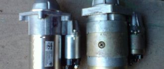
Electromagnetic horns differ in the design of the sound emitter:
- Disc horns (“pancakes”). They are manufactured in two versions: non-separable and collapsible. In addition, it can be closed or open.
- Snail sounds. They are curved, making them difficult to install. The open end of the socket should point forward. “Snails” make it possible to get a very loud sound.
- Horns have a tube that looks like a straightened snail. Outwardly they look like a horn or a trumpet. They are convenient to install under the hood, but their sound power is weak.
When choosing a sound device, you should pay attention to several nuances:
- Before purchasing, you should evaluate the capabilities of the battery. It is important that its charge is sufficient to power the buzzer, as it consumes a large amount of energy.
- You should check with the seller whether the horn needs additional power or a compressor.
- High frequencies produce a subtle sound. Low frequencies are suitable for bass lovers.
- It must be remembered that trucks have a 24 V on-board network, and passenger cars have 12 V. It should be noted that the use of “quacks” and special signals is prohibited.
The feasibility of self-repair
Self-repair is possible if the driver is well versed in electrical engineering. Car enthusiasts who do not have such skills can replace a fuse, relay or clean the terminals.
If the contacts are not oxidized, but burned out, then it is easier to install a new signaling device. If you know how to make a signal on a VAZ 2107, you can do the repairs yourself - this will give you the opportunity to gain experience in electrical repair work and save money at the service station.
If the signal on a VAZ 2107 is lost, it should be repaired as quickly as possible, since its malfunction increases the risk of an accident.
In addition, according to traffic rules, operating a car without a sound signal is prohibited. Therefore, it is impossible to pass a technical inspection with a faulty horn.