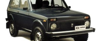
Ford Fusion subcompact
European assembly was produced at a plant in Germany in 2002, 2003, 2004, 2005, 2006, 2007, 2008, 2009, 2010 and 2011 with gasoline and diesel engines of 1.2 1.4 1.6 liters. During this period, the car was restyled once. In our material you will find a description of the Ford Fusion fuse and relay blocks, as well as their diagrams and photographs. Separately, we note the fuse responsible for the cigarette lighter. In conclusion, we will offer you a complete repair and maintenance manual for your review.
The purpose of block diagram elements may differ from those presented. Check the description with your technical documentation. And if you have another generation of Ford Fusion (models from 2012), then study this publication.
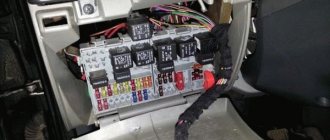
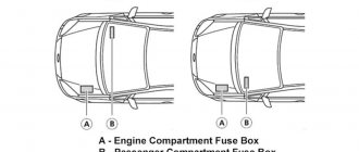
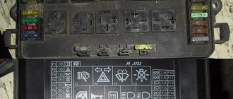
Fuse box in the passenger compartment
The panel inside the car is installed under the tidy on the glove box side. The location of the block is unchanged for cars before and after the 2012 restyling.
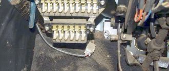
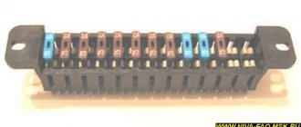
A number of fusible links and relays are installed inside the module, which are responsible for auxiliary devices and additional devices that are not related to the operation of the power plant. To make life easier for the user, the manufacturer writes a schematic description of all elements on the inside of the cover.
Typical breakdowns and their symptoms
If the door lock does not work on the Ford Fusion, then it is necessary to establish the cause of the malfunction. Basic moments:
- Dust, dirt or the element has not been lubricated for a long time.
- Oxidation and freezing occurred due to moisture ingress and concentrate ingress. An electrical leak may occur, or it may be caused by washing, precipitation, or sudden cold snap.
- Incorrect adjustment was made. High installation or too small stroke of this part.
- False alarm when dust or water gets into the gap between the contacts.
- Corrosion. Regular lubrication of the internal niche with an anti-corrosion agent will help prevent damage.
Problems can be prevented by regular diagnostics, preventative maintenance and a sealed boot that completely covers the button.
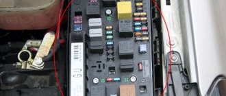
Fuses under the hood
The main part of the inserts responsible for the motor is located near the battery. The panel is attached to the positive terminal and is hidden under the battery housing. To access the fuses you will need to disconnect the battery and remove it from its seat. In the 2007 pre-restyling version, there was an auxiliary mounting block where power relays were installed.
Removing and installing the battery
You will need: a 10mm wrench, a 13mm socket, and an extension cord.
1. Turn off the ignition (if it was on) and open the hood.
2. Loosen the nut of the coupling bolt of the ground wire lug...
3. ...and remove the wire tip from the negative terminal of the battery.
4. Remove the protective cover of the wire tip of the “plus” terminal of the battery...
5. ...loosen the nut...
6. ...and remove the wire tip from the “plus” terminal of the battery.
7. Unscrew the two nuts securing the clamping bar...
8. ...and remove the bar.
9. Remove the battery.
10. To remove the battery shelf, press the lock...
11. ...and move the fuse box aside.
12. Remove the three bolts securing the battery shelf...
13. ...two screws securing the engine control system controller...
14. ...take the controller out of the bracket on the shelf and move the controller to the side.
15. Remove the battery shelf.
16. Install all previously removed parts in reverse order. Before connecting the wires, clean the battery terminals and the inside surfaces of the wire lugs with fine-grit sandpaper. Connect the wires in the reverse order of removal, observing polarity. After connecting the wires to the battery terminals, apply a thin layer of Litol-24 or similar grease to the metal ends of the wires and the exposed surfaces of the terminals (copper-containing conductive greases are most preferred).
Replacing the battery for Fiesta and Fusion
Since both cars are designed for “bottom” battery mounting, the car owner will need to use two keys from a standard car set - a flat 10 and a 13 socket.
The first step after opening the hood is to loosen the clamp on the battery electrode, marked with a minus sign, using a 10mm key. The clamp is removed from the electrode.
Then a similar operation is performed on the positive terminal.
After the wires are disconnected and moved to the side, use a socket wrench (preferably with an extension) to unscrew the bolt at the base of the battery, which holds the pressure plate. The plate is removed.
The old battery is removed and a new one is installed in its place.
After the new battery is in place, the clamping bracket is screwed back on. Then the positive clamp is attached and securely tightened, and the “ground” is attached last.
Why do you remove the battery for the winter?
Guys, everything is simple here - they remove it so as not to “kill” the battery! If the car is not in use, but the terminals are connected to the battery, then the discharge microcurrents are still present, of course, for some the leakage is much larger, for others it is much smaller, but in any case it is present (by the way, we read here how to check it). Also, do not forget about self-discharge currents; even the most ideal battery can discharge itself during a long period of inactivity. YES, to be honest, batteries are not always clean on top, that is, they may contain dirt, moisture (for example, precipitation, evaporation, etc.), antifreeze and much more. All this can drain the battery, albeit slowly but surely.
Post-installation setup
If 6000 CD was nevertheless installed back into the Ford Fusion, then the date and time settings will be lost. They should be updated because the displayed data is also transferred to the on-board computer. As a standard, after a reboot, the head unit shows 12 noon, the date corresponds to the release date of the Ford Fusion. If you remove and install it, this time will be shown again. Unlocking also implies the output of such data.
Setting the date and time
The standard radio has a special “Clock” button (CLOCK) in the upper right panel. By pressing it, you can easily set both the date and time.
By pressing the “right” and “left” buttons, you can switch the selection: from time to date, from day to year or month. When you select one of the areas, you can change it using the slider. You should scroll it until you get the desired number, then remove your finger from the setting buttons and click either on the menu or again on “Clock”.
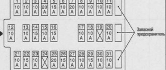
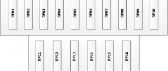
Ford Fusion Fuse Diagram
Further descriptions of fuses and relays are given on the 2008 machine.
Let's consider the interior module installed under the glove compartment.
| Location | Description |
| 1 | Backup fusible element. |
| 2 and 3 | Tow hitch fuses. |
| 4 | Heater drive power supply. |
| 5/6 | Supply voltage to the ABS system. |
| 7 | Automatic transmission Durashift module. |
| 8 | Exterior mirror power drive |
| 9/10 | Left and right headlights in low beam mode. |
| 11 | DRL connection. |
| 12 | Controller of the ECU section responsible for the fuel injection system. |
| 13 | ECM module on diesel versions. |
| 14 | Supply voltage to the starter relay. |
| 15 | Same for the fuel pump. |
| 16 | ECU power supply circuits. |
| 17 | Steering column switches for external lighting devices. |
| 18 | Power supply for the standard radio. |
| 19 | DRL lighting |
| 20 | Dashboard power supply, rear room lighting. |
| 21 | Reserve cell. |
| 22/23 | Respectively for left and right dimensions. |
| 24 | Power supply for central locking and horn. |
| 25 | Supply voltage to emergency lights. |
| 26 | Rear window heating system. |
| 27 | Klaxon and interior lamps. |
| 28 | Supplying power to the generator excitation winding. |
| 29 | Front cigarette lighter |
| 30 | Ignition system control. |
| 31 | Steering column switch for external lighting. |
| 32 | Heated rear view mirrors. |
| 33 | Switches on the dashboard. |
| 34 | Reserve position. |
| 35 | Heated front seats. |
| 36 | Operation of window lifters. |
| 37 | Power supply for the ABS controller. |
| 38 | General electronic unit. |
| 39 | Airbag control. |
| 40 | Automatic transmission controller |
| 41 | Backup fuse. |
| 42/43 | Windshield heaters. |
| 44 | Power supply of the standard radio from the battery. |
| 45 | Stop lights. |
| 46 | Power supply for front window wipers. |
| 47 | Similarly for the glass of the rear of the car. |
| 48 | Reversing lamp. |
| 49 | Electric heater fan drive. |
| 50 | Fog lights. |
| 51 | Rear cigarette lighter. |
| 52/53 | Left and right headlights in high beam mode. |
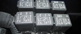
| Relay | |
| 1 | Headlight switches. |
| 2 | Heated windshield. |
| 3 | Auxiliary ignition system. |
| 4/5 | Headlight switches for headlights in low/high beam mode. |
| 6 | Power supply for the fuel circuit and ignition system. |
| 7 | Starter field windings. |
| 8 | Fan drive of the power plant cooling system. |
| 9 | The daylighting option only applies to Scandinavian countries. |
| 10 | Rear socket power. |
| 11 | The main ignition system, carried out through an immobilizer, regenerator. |
| 12 | Backup relay. |
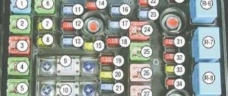
We should also consider the module installed under the hood of the car.
| Marking | Description |
| F.A. | Auxiliary heating power supply system. |
| FB | Transmission controllers |
| F.C. | Additional stove or glow plugs on a diesel engine. |
| FD | Radiator cooling fan and air conditioning clutch. |
| F.E. | Common electronic lighting module for the entire vehicle. |
| FF | Ignition system. |
| FG | Basic electronics of the engine and lighting elements. |
| FH | Windshield heaters, ABS and ESP systems. |
A relay module is installed nearby.
| Serial number | Description |
| 1 | Switching off the A/C position when opening the throttle. |
| 2 | Radiator fan, high rotation speed. |
| 3/4 | Power supply for interior auxiliary heating systems. |
Ignition relay
The mains are powered through the FF switch installed under the hood of the machine.
Trunk release safety device
Element 24, mounted in the interior compartment, is responsible for the lid lock and other locking devices.
central locking
The information is listed above.
Fuel pump relay and fuse
It is installed in the passenger compartment at position 15. The switch is placed under the instrument panel or its role is played by the ECU.
Cigarette lighter fuse: where is it located?
The car is initially equipped with 2 sockets. Inserts 29 and 51 installed in the cabin are responsible for their nutrition.
Starter fuse and relay
They are mounted in two positions in the cabin - 14 and 28. Depending on the configuration, power relays can be installed side by side, in positions 2 and 3. The starter retractor is installed in the usual place and is characterized by increased reliability and simplicity of design.
Horn fuse
It is activated through element 24. The horn is protected by insert 27.
Stop signal
Power is supplied through fuse 45, mounted in the interior panel.
ABS fuse: where is it located?
The system is protected by two inserts. Sensors - fuse 5. Device controller - insert 6. The elements are located under the dashboard.
Reverse
The light bulb is connected to the on-board network through element 48.
Wiper fuse
The front and rear windshield wipers have 46/47 fuses.
Low beam relay
The lighting module is made through relay 4 installed in the cabin. The lighting unit is controlled by the FE element.
Instrument lighting fuse
The lighting is connected to the on-board network via insert 11.
Radio tape recorder
The system has 2 fuses due to the wiring going to relieve the load from the fuse link and wires. Here, 18/44 elements are responsible for supplying voltage.
Turns relay
They should not be found in mounting panels or under the interior trim. The GEM, a unit prepared specifically for this purpose, is responsible for the operation of the device.
Generator relay
Installed inside the generator. The device is mounted on the working shaft of the unit and is removed only after complete disassembly of the carrier.
Cooling fan relay
The high speed power supply system is supplied via the FD relay installed under the hood. The low-revving part is connected from element 2 in the cabin.
Dimension fuse
The power system is organized from inserts 22/23 for the left/right side of the car.
Glow plug relay - where is it located?
The system is implemented only on diesel engines. Here the power line is routed through the FC switch.
Heater fuse
The interior heater control system is installed through element 49. The power cores are connected from the R3/4 relays. All elements are installed in the cabin under the dashboard.
Windshield washer
The power circuits of the pump motor are connected to the on-board circuit from fuse 46 located in the passenger compartment.
Mirrors
The adjustment drive is connected to the battery through insert 8. The heating circuits are connected to the lines through element 32.
Window lifters
The buttons are powered from insert 36 installed under the glove box. The power cores of the servo drives are powered from the FH relay of the engine compartment unit.
What batteries are supplied with Fiesta and Fusion at the factory?
The European design bureau of the American automobile brand, based on the fact that the engine sizes of both cars are small, decided to equip all trim levels on all generations of both models with one single battery size.
Batteries are used in the European size, which is the most widely used on the battery market - 242x175x175 mm. The capacities of models belonging to this group range from 55 to 63 A/h, the starting current strength is in the range of 490-640 A.
The design of the engine compartment assumes a reverse arrangement of electrodes on the power supply devices. Fastening is done using a lower pressure plate, so only models with a plastic protrusion at the bottom of the device body are suitable.
European version
Regardless of which of these cases you have, you need to know how to remove the bumper so that you don't break anything anywhere or damage the bumper itself. How to remove the front bumper on a Ford Fusion with your own hands - step-by-step instructions 1.
Removing the front bumper of the Fusion does not require a lift or inspection hole; it is enough to have a clean area where you can park the car and do the work. To prevent anything from getting cold, place cardboard or polystyrene foam under the “butt” or “to the extreme” of some thick old jacket.
Tighten the handbrake or shift into gear. Raise the hood, remove the “-” terminal of the battery. Next, you need to dismantle the fender liners to make it better to remove the wheel, but if you don’t really want to, then you don’t have to remove it.
Using an asterisk of suitable diameter, unscrew the screws securing the fender liner.
Batteries suitable for installation on Ford Fiesta and Fusion
Here are a few battery models for the cars in question that are worth paying attention to:
- The most affordable in terms of cost are two models from German manufacturers - Varta Blues D59 and Bosch S4 004. You must understand that Varta-Bosch has long been a single production concern, so the question of choice in this case is solely a preference for the name on the sticker devices. Moreover, both models are produced at the same plant in Romania and have the same characteristics - capacity 60 A/h, current 540 A.
- The Korean model from Inci has similar characteristics - Aku SUPR A 60 RS (in a low case) - capacity 60 Ah, current 540 A. The fact that Inci is a supplier of “stock” devices for many world brands indicates high reliability products of this brand.
- Domestic products in the group are represented by the model from Forse 60R (in a low case) with high performance - capacity 60 A/h, current strength at 600 A.
- An interesting solution is offered by the Turkish brand MUTLU Mega Calcium 60R - a battery capacity of 60 A/h with a starting current during a cold start of 540 A. The addition of calcium by the manufacturer to the lead plates of the battery significantly increases its service life.
- The top device in terms of its performance is the product from the Korean BOST - model Premium 63R (56377) with a capacity of 63 Ah and a current of 640 A.
All of the listed models have reverse polarity and are designed for fastening using a lower clamping bar or bracket.
Ford Fusion: replacing fuses
To change the insert on a car you will need to follow a simple sequence of steps.
- De-energize the car by disconnecting the terminals from the battery.
- Open the cover of the mounting block and find the required element.
- Using special tweezers or forceps, remove the damaged element from the socket. At the same time, it is unacceptable to remove the element with bare hands - this can damage the seat.
- Next you will need to assemble the entire structure in reverse order.
Dismantling process
To begin with, you should understand that removing the bumper can be quite easy and simple, and does not require much effort. There is also no need to look for special-purpose equipment, such as in engine-related operations. Also, to dismantle the bumper, you don’t need a hole or a lift, you only need a flat surface.
It is worth understanding that in order to remove the front bumper you will need to remove the accompanying parts, so you will need a jack and a set of tools, which must include Torx sprockets and other attachments.
Let's get started with the work:
- We remove the terminal from the battery so as not to accidentally short-circuit anything and create even more problems.
- Remove the front wheels.
- To make the process easier, it is necessary to remove the fender liners and dirt-reflecting flaps.