Nissan Primera
It was produced in 3 generations with sedan, station wagon and liftback bodies. The first generation - p10, was produced in 1990, 1991, 1992, 1993, 1994, 1995. The second is p11, in 1996, 1997, 1998, 1999, 2000. Third - p12, in 2001, 2002, 2003, 2004, 2005, 2006 and 2007. We will present information describing the fuse and relay blocks of the Nissan example p11 and p12 (2nd and 3rd generations), their photographs, diagrams and the purpose of the elements. Separately, we note the cigarette lighter fuses.
Fuses and relays P12
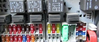
We have 2 boxes with preds, one under the hood next to the battery, the second above the left knee (I’m talking about the European one). Here are the fuse numbers.
transcript of the previous ones, maybe somewhere I made a slight mistake with the translation, but I tried to describe in as much detail as possible 1. audio system, navigation, audio-video communication channel, camera, instrument panels, clock, cigarette lighter, telephone 2. cruise control 3. door locks 4. cigarette lighter, additional socket 5. cruise control, automatic transmission shift lock system, warning lights, brake lights, ESP, ABS, brake switch, cruise brake switch 6. rear PTF 7. heated glass, navigation, anti-theft system 8. heated seat 9. cruise control, cruise brake switch 10. turn signals and hazard lights, CVT gearshift lock system, audio, navigation, audio-video communication link, sound alarm, clock, power window, defroster, auto-dimming mirror, headlight washer, cleaner and washer (auto mode ), door locks, NATS (immobilizer), remote central locking, electric headlight adjustment, air conditioning, light sensor, interior light, sunroof, check engine and OBD-2 connector, telephone. 11. speed sensor, automatic transmission fluid temperature sensor, TCM unit power supply 12. cruise control, turn signals and hazard lights, automatic transmission fluid temperature sensor, TCM unit power supply, speedometer, tachometer, temperature, oil and fuel level indicators, automatic transmission indicator, sound alarm, heating glass, door locks, anti-theft system, immobilizer, remote central locking, air conditioning, check engine and OBD-2 connector, lighting, interior light, tire pressure monitoring system. 13. anti-theft system, additional non-standard whitefish (we have wiring), interior lamp, route lights, mirror illumination in the visor, trunk lighting, heated mirrors 14. AC fan motor 15. AC fan 16. AC fan motor 17. fuel injectors, unit relay ECM, fuel pump 18. airbags 19. empty 20. lambda probes (oxygen sensors), carbon filter purge solenoid valve, fuel injectors, cooling fan regulator, starting system, air conditioning, power windows 21. start signal (starter), light sensor 22 . cigarette lighter 23. side mirrors, heated glass 24. empty (reserved for console socket) 25. air conditioner, glass cleaner and washer 26. glass cleaner and washer, rear window cleaner and washer 27. lambda probes (oxygen sensors), fuel injectors 28. rear window cleaner and washer 29. fuel pump 30. glow control system, check engine and OBD-2 connector, speed sensor, ABS, ESP, airbags, charging system, light sensor, speedometer, tachometer, temperature, oil level indicators and fuel, warning lights, backlight, NATS, automatic transmission indicator, navigation, air conditioning, turn signals and emergency lights, reversing light, park/neutral switch, rear view camera control system. 31. ABS, ESP 32. dimensions, license plate lighting, light sensor, electric headlight adjustment, front and rear PTF, backlight, sound alarm, headlight washer, power window switch illumination 33. audio system, navigation, display, camera, clock, telephone 34. power ECM unit and ECM relay, MAF, crankshaft angle sensor, camshaft angle sensor, intake valve timing solenoid valve, ignition signal, EGR volume control system, charcoal canister purge solenoid valve, EDU unit, fuel injectors, turbine control valve , speed sensor 35. signal, charging system 36. right xenon headlight 37. left xenon headlight 38. empty 39. empty 40. electric drive, relay and throttle motor 41. left halogen headlight, electric corrector 42. right halogen headlight, rear PTF 43 . front PTF 44. solenoid valve for setting the intake valve timing, ignition signal, ECM unit relay, EGR volume control system, speed sensor A. the most important one from the battery B. to breakers 1(*1) and 2(*2) C. regulator cooling fan 1 D. cooling fan 2 control E. headlight washer pump F. heat control system (diesel) G. ignition H. ignition I. ABS, ESP J. ignition K. ABS, ESP *1 door locks and remote control, power windows , sunroof, electric seats *2 power windows
Relay in the cabin left hand drive
Relay in the cabin right hand drive
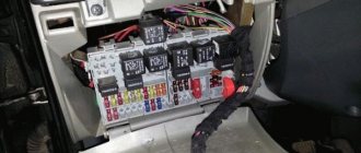
Relay under the hood
On P12 European 1.8 and 1.6 manual transmissions, only 3 relays are installed in this block and one socket is free. Relay options under the hood
The fuel pump relay lives near the left leg.
there are three relays on the back of the fuse box, here they are
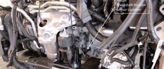
Well, and the general picture, where the blocks are and the ECM relay is visible
How to check the fuel pump relay yourself
The fuel pump relay is a device that provides and stops power supply to the fuel pump upon command from the ECU. The device is fully responsible for controlling the fuel pump, and also performs certain additional functions, which depend on the specific brand and equipment of the car. For example, on cars with automatic transmission, if it is necessary to activate the kick-down mode (intensive acceleration), the specified relay is activated.
Where is the fuel pump relay located?
To answer the question of where the fuel pump relay is located, you need to know exactly the make and model of the car. The installation location on different cars is the area near the injection control unit; the solution can be installed under the dashboard near the fuse box, etc.
Often, if they need to make their own repairs, car enthusiasts are interested in where the fuel pump relay for the VAZ 2110 injector is located. On this model, the fuel pump relay is located near the passenger's left foot under the dashboard. It should be added that the fuel pump fuse is also installed nearby.
Signs and Symptoms of a Bad Fuel Pump Relay
Let's start with the fact that the fuel pump is controlled through a relay according to the following general scheme:
- the driver inserts the key into the lock and turns on the ignition;
- after turning on the ignition, the relay turns on the fuel pump for 2-3 seconds, which is necessary to create pressure in the fuel rail.
- then you can hear a characteristic sound as the fuel pump relay clicks, which has turned off the fuel pump;
- subsequent operation of the fuel pump will be possible under 2 conditions: rotation of the engine by the starter during startup and further independent operation of the already running engine.
- after turning off the ignition and stopping the engine, the relay turns off the fuel pump immediately or after 1 second.
Also on some cars the device serves as a kind of engine speed limiter. If the engine speed approaches maximum and begins to exceed the permissible threshold, the fuel pump is switched off via a relay. The gasoline supply stops, the speed decreases, after which the element supplies power to the pump again.
It should be additionally noted that on some vehicle models the fuel pump does not turn on after turning the key in the ignition, but at the moment the driver's door is opened. This solution allows you to quickly start the engine, as it ensures that the necessary operating pressure is created in the fuel system in advance. In other words, the pump pumps gasoline until the driver decides to insert the key and start the engine.
If the relay malfunctions, then power may not be supplied to the fuel pump. The second option is that the pump hums or hums constantly, that is, it does not turn off a few seconds after the required pressure is created in the fuel line. In the first case, the engine often cannot be started because the pump does not pump and there is no gasoline in the fuel rail.
In the second case, the fuel pump relay gets stuck (the fuel pump relay does not work) and the battery charge is consumed for the constant rotation of the fuel pump motor. Let us add that on some cars, starting the engine is possible even if there are certain malfunctions in the operation of the element, since the pump relay connection diagram allows the device to operate while the starter is cranking.
Checking the fuel pump relay yourself
At the beginning of the test, you need to get to the following elements: the pump fuse and its relay. Having decided which relay is responsible for the fuel pump, you should also inspect the fuse. Additionally, you need to check the fuse because the fuel pump relay heats up and then does not respond in a timely manner or does not operate at all due to a malfunction of the specified fuse.
The easiest way to check is to install a known working device. Also in the list of general ways to check a fuel pump relay with your own hands, you can highlight one when a test lamp is connected instead of a relay. After turning on the ignition, the light should light up. You can also place a jumper on the terminals during diagnostics. If after turning the ignition key the fuel pump starts to work, then this indicates a malfunction in the fuel pump control device.
Now let's look at another available way to check using the example of a VAZ 2110 car. The fuel pump relay itself in this model is located near the fuse.
- To check, you will need a multimeter or a test light of no more than 0.25 A. Next, you should alternately measure the voltage at the control terminals of the device, simultaneously fixing the contact to ground. This method allows you to accurately determine whether the fuel pump relay needs to be replaced.
- If the warning light does not light up, the pump fuse is working or replaced with a known working one, then attention should be paid to the wiring from the relay to the computer. At the same time, the possibility of malfunctions in the engine control unit should not be ruled out.
Finally, we add that the element may also refuse to work or stick after failures or unqualified installation of a car alarm/immobilizer. The fact is that security and anti-theft systems with an engine start blocking function are often based on interrupting the power supply to the fuel pump. In this case, these systems must be diagnosed separately.
Source: https://KrutiMotor.ru/zamena-rele-benzonasosa/
Purpose of fuses and relays Nissan Primera P12 (manufactured from 2002 to 2007)
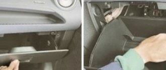
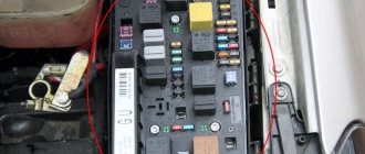
Most power supply circuits for vehicle electrical equipment are protected by fuses. Headlights, electric fan motors, fuel pump and other powerful consumers are connected via a relay. Fuses and relays are installed in mounting blocks, which are located in the vehicle interior at the end of the instrument panel on the left side (on the left front side of the side panel) and in the engine compartment to the left of the battery. Most fuses are installed in the passenger compartment fuse box, located on the front side of the body under a plastic cover. Circuits protected by fuses (fuse numbers are shown in the photo).
In the cabin
It is located in the instrument panel behind the protective cover on the driver's side.
p, blockquote 4,0,0,0,0 –>
p, blockquote 5,0,0,0,0 –>
Option 1
Photo - diagram
p, blockquote 6,0,0,0,0 –>
p, blockquote 7,0,0,0,0 –>
Description of fuses
p, blockquote 8,0,1,0,0 –>
| 1 | 10A Passive safety system |
| 2 | 10A Additional interior equipment |
| 3 | 10A Instrument cluster |
| 4 | 15A Windshield washer pump |
| 5 | 10A Heated exterior mirrors |
| 6 | 10A Power mirrors, audio system head unit |
| 7 | 10A Brake lights |
| 8 | 10A Interior lighting |
| 9 | 10A Body electrical control unit |
| 10 | Reserve |
| 11 | 10A Lamp for side light of right rear light |
| 12 | 10A Left tail light lamp |
| 13 | 10A Instrument cluster |
| 14 | 10A Additional interior equipment |
| 15 | 15A Engine cooling fan motor |
| 16 | 10A Heating, air conditioning and ventilation system |
| 17 | 15A Engine cooling fan motor |
| 18 | Reserve |
| 19 | 15A Socket for connecting additional equipment ( cigarette lighter ) |
| 20 | Reserve |
The cigarette lighter is controlled by fuse number 19 at 15A.
Relay purpose
p, blockquote 10,0,0,0,0 –>
- R1 - Electric heater fan
- R2 - Additional equipment
- R3 - Relay (no data)
- R4 - Heated exterior mirrors
- R5 - Immobilizer
Option 2
Photo - diagram
p, blockquote 11,0,0,0,0 –>
p, blockquote 12,0,0,0,0 –>
Designation
p, blockquote 13,0,0,0,0 –>
Nissan Primera P11 Fuse Box Explanation
Nissan Primera
Available in 3 generations with cars, vans and lifts. 1st generation - p10, completed in 1990, 1991, 1992, 1993, 1994, 1995. 2nd - p11, in 1996, 1997, 1998, 1999, 2000.
Third - p12, in 2001, 2002, 2003, 2004, 2005, 2006. and 2007. We will present information describing Nissan fuse and relay blocks using examples p11 and p12 (2nd and 3rd generation), photographs, diagrams and parts assignment.
Pay special attention to the cigarette lighter fuses.
Blocks in the cabin
Layout of electronic components, fuses and relays
Business date, meeting
- Fuse box;
- switching relay;
- brake light switch;
- protective device
- speaker relay;
- headlight washer relay;
- speaker relay;
- anti-theft system (immobilizer);
- headlights corrector;
- code lamp relay;
- airbag control unit;
- automatic transmission control unit;
- the engine control unit;
- air conditioning relay;
- fuel pump relay;
- fog relay;
- power window relay;
- rear window defrost relay;
- fuse box bracket;
- signal relay;
- switching relay;
- ignition system relay;
- switching relay;
- fan fan relay
P12
Blocks in the cabin
Scheme
Main block with fuses
It is located in the instrument panel behind a protective cover, on the back of which a current diagram with decoding of the elements will be printed.
Photo - diagram
Description
| 1 - 10A | Audio system |
| 2 - 10A | Cruise control |
| 3 - 10A | Electric trunk lock |
| 4 - 20A | Trunk electrical outlet |
| 5 - 15A | Brake lights |
| 6 - 10A | Fog lights |
| 7 - 20A | Heated rear window (tailgate glass) |
| 8 - 10A | Heated front seats |
| 9 - 10A | Cruise control |
| 10 - 10A | Power supply for electronic devices |
| 11 - 10A | Automatic transmission control system |
| 12 - 10A | Power supply for electronic devices |
| 13 - 10A | Interior lamps |
| 14 - 15A | Air blower motor |
| 15 - 10A | Air conditioner |
| 16 - 15A | Air blower motor |
| 17 - 10A | Engine management system |
| 18 - 10A | Additional safety system (SRS) |
| 19 | Reserve |
| 20 - 10A | Engine management system |
| 21 - 10A | Starter solenoid relay |
| 22 - 15A | Cigarette lighter |
| 23 - 10A | Electric drives for controlling external rear view mirrors |
| 24 - 15A | Center console electrical outlet |
| 25 - 20A | Windshield wiper |
| 26 - 15A | Windshield and tailgate washers |
| 27 - 10A | Sensors |
| 28 - 10A | Tailgate glass cleaner |
| 29 - 15A | Fuel pump |
| 30 - 10A | Instrument cluster |
| 31 - 10A | Anti-lock brake system (ABS) |
Fuse number 22 at 15A is responsible for the cigarette lighter.
Relay on the front side of the fuse box panel
Designation
- rear window heating relay;
- throttle motor relay;
- fog lamp relay;
- power window relay;
- relay interrupters;
- relay interrupters.
Relay on the back of the fuse box panel
Purpose
- ignition relay;
- accessory relay;
- air blower relay for ventilation, heating and air conditioning systems
Blocks under the hood
Scheme
Fuse block
Photo - diagram
Description
| 1 - 120A | 1st main fuse |
| 2 - 80A | Consumers with ignition on |
| 3 - 50A | Anti-lock braking system pump electric motor |
| 4 - 40A | Ignition switch (lock) |
| 5 - 30A | Anti-lock braking system solenoid valves |
| 6 | Reserve |
| 7 | Reserve |
| 8 - 10A | parking lights |
| 9 - 15A | Audio system |
| 10 - 10A | Engine management system |
| 11 - 15A | Sound signal |
| 12 | Reserve |
| 13 | Reserve |
| 14 - 15A | Low beam (left headlight) |
| 15 - 15A | Low beam (right headlight) |
| 16 - 15A | Throttle valve motor |
| 17 - 15A | High beam (left headlight) |
| 18 - 15A | High beam (right headlight) |
| 19 - 15A | Fog lights |
| 20 - 20A | Ignition coils |
| 21 - 80A | 2nd main fuse |
| 22 | Reserve |
| 23 - 30A | Headlight washers |
| 24 - 40A | 2nd radiator fan motor |
| 25 - 40A | 1st radiator fan motor |
| 26 - 40A | Electric windows |
Nissan Primera Relay Where Are They Located?
Nissan Primera
It was produced in 3 generations with car, station wagon and liftback bodies. 1st generation - p10, performed in 1990, 1991, 1992, 1993, 1994, 1995. 2nd - p11, in 1996, 1997, 1998, 1999, 2000.
Third - p12, in 2001, 2002, 2003, 2004, 2005, 2006 and 2007. We will present information describing the fuse and relay blocks of the Nissan example p11 and p12 (2nd and 3rd generations), their photos, diagrams and the purpose of the parts.
Let us separately note the cigarette lighter fuses.
Layout of electrical blocks, fuses and relays
- fuse box;
- relay-interrupter;
- brake light switch;
- device panel;
- speaker relay;
- headlight washer relay;
- speaker relay;
- anti-theft system (immobilizer);
- headlights corrector;
- code light relay;
- airbag control unit;
- control unit Automatic transmission;
- engine control unit;
- air conditioning relay;
- fuel pump relay;
- fog light relay;
- power window relay;
- rear window defroster relay;
- fuse box bracket;
- security alarm relay;
- relay-interrupter;
- accounting ignition system relay;
- relay-interrupter;
- interior blower relay
From top to bottom, from left to right.
- Fan motor
- air conditioner
- Dashboard
- INJ (Injection system)
- Electrical components/ interior lamp
- Fan motor
- Turn signals
- Fuel pump
- Airbags
- Oxygen and idle speed sensor
- Speed sensor
- Rear window defroster (if equipped)
- Electrical components of the dashboard
- Cigarette lighter
- Abs
- Starter signal
- Rear brush
- Fog lights
- Mirrors
- Stop signals
- Brushes
- Additional socket
- Audio system
- Control Automatic transmission
- Emergency alarm
Purpose of the relay in the mounting block Nissan Almera Classic
- The fuse 3rd from the top is responsible for the cigarette lighter; the middle fuse in the row is 15A.
- Table - diagram
- Table with designation
The fuse responsible for the cigarette lighter is the second fuse in the top row at 15A. In the picture it is circled in reddish.
- fuse box under the hood;
- Abs control unit;
- relay block;
- windshield wiper motor;
- preheating relay for cars with a diesel engine;
- left headlight relay;
- horn relay;
- radiator fan relay;
- engine control unit relay;
- auxiliary equipment relay;
- radiator fan relay 1;
- relay 4.5 radiator fan;
- neutral relay;
- air conditioning relay;
- rear window wiper relay;
- right headlight relay;
- windshield wiper relay
An example photo of a block with a relay.
The number of parts and their purpose may differ from those presented. A lively transcript will be printed on the lid.
Photo - diagram
Photo - diagram
Lyokha & fuses and relays in Mitsubishi Carisma
Translation of symbols into Russian
- hazard - emergency alarm
- horn - sound signal
- alt s — generator winding excitation signal
- tail - rear dimensions
- abs sol - abs solenoid
- ign sw - on ignition
- abs mtr - abs motor
- battery - battery
- h/lamp rh - right headlight
- h/lamp lh - left headlight
- audio - radio
- eng cont - engine control unit
- ign coil - ignition coil
- throt motor - throttle valve drive
- inj - something about the injector
- hid rh - xenon right
- hid lh - xenon left
- rr defog - rear fog lights
- rad fan 1,3.5,3 — radiator propeller 1,2.4,3
- main - main before xs where
- power window - el. window lifters
It is located in the device panel behind the protective cover; on the reverse side there will be a vital diagram with a breakdown of the parts.
Source: https://vivauto.ru/rele-nissan-primera-gde-nahodjatsja/
Description of fuses: location, diagrams, price
- Recommendations for maintenance of fuses2.1
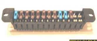
In all three generations of Nissan Primera P10, P11, P12, knife-type protection modules are preinstalled.
Layout of relays - switches
DesignationWhich is responsible for what/what provides
| K 1 | Headlight |
| K2 | Throttle valve |
| K 3 | Window lifters |
| K 4 | Rear fog lights |
| K5 | Ignition |
| K 6 | Fuel equipment |
| K 7 | Electrical equipment |
| K 8 | Reservation |
| K9 | Reservation |
| K 10 | Reservation |
| K11 | Reservation |
| K 12 | Stop signals |
| K 13 | Backlight |
| K 14 | Interior lighting |
| K 15 | Reservation |
| K 16 | Reservation |
| K 17 | Reservation |
| K 18 | Electronic powertrain control unit |
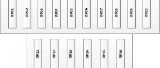
Fuse installation diagram
Marking / amperageWhat it is responsible for (with description)
| F (F-1) / 20 | Speedometer, tachometer, gauges |
| F (F-2) / 5 | Exchange rate stabilization system |
| F (F-3) / 10 | ABS |
| F (F-4) / 10 | Reservation |
| F (F-5) / 20 | Reservation |
| F (F-6) / 30 | Glove compartment lighting |
| F (F-7) / 30 | Heater fan (stove) |
| F (F-8) / 20 | Air conditioning system |
| F (F-9) / 10 | Fuel system, fuel pump |
| F (F-10) / 10 | Safety system |
| F (F-11) / 10 | Reservation |
| F (F-12) / 10 | Powertrain sensor |
| F (F-13) / 30 | Side mirrors |
| F (F-14) / 30 | Stop signals |
| F (F-15) / 10 | Car socket |
| F (F-16) / 15 | Additional electrical network |
| F (F-17) / 15 | Hazard warning lights, turn signals |
| F (F-18) / 20 | Reservation |
| F (F-19) / 20 | Heated rear window |
| F (F-20) / 20 | Oxygen sensor |
| F (F-21) / 20 | Reservation |
| F (F-22) / 20 | Window lifters |
| F (F-23) / 20 | Automatic transmission controller |
| F (F-24) / 20 | Oven heater, cigarette lighter, interior lighting |
| F (F-25) / 15 | Reservation |
| F (F-26) / 15 | Reservation |
| F (F-27) / 20 | Reservation |
| F (F-28) / 15 | Car horn |
| F (F-29) / 15 | central locking |
| F (F-30) / 20 | Reservation |
| F (F-31) / 15 | Electrical power system |
| F (F-32) / 20 | Windshield wipers |
| F (F-33) / 20 | Headlight washers |
| F (F-34) / 20 | Rear window washer |
| F (F-35) / 20 | Fuel equipment (optional) |
The price of the original mounting block for the Nissan Primera P12 assembly starts from 3,500 rubles, analogues from 3,000 rubles. Relays - switches priced from 550 rubles.
Signs of faulty fuses on a third generation Nissan Primera
- An indicator on the dashboard indicates a breakdown of mechanisms and equipment in the engine compartment;
- Power units do not operate when current is supplied or modes are activated;
- The fuse box is hot to the touch, with a clearly uncharacteristic temperature;
- The smell of melted plastic can be heard at the location of the protective modules.
Causes of fuse failure
- Violation of the terms of technical inspection of the vehicle, as a result of which the equipment ceases to function properly;
- Purchase and subsequent installation of non-original spare parts;
- Violation of the technology for installing spare parts and components;
- Damage to the mounting block with protective modules;
- Short circuit in electrical wiring;
- Damage to cable insulation;
- Oxidation of contacts, condensation, moisture ingress into the protective housing;
- Loose terminal contacts.
Replacing fuses on Nissan Primera P12
Preparatory stage:
- Flat head screwdriver;
- Additional lighting;
- A set of new relays - switches, fuses;
- Tweezers for removing melting elements.
Sequence of actions when replacing modules in the cabin:
- We place the car within the perimeter of the repair area, block the rear row of wheels with wheel chocks, and squeeze the parking brake;
- Left-hand drive: open the driver's door, a mounting block is installed to the left of the steering column, remove the cover;
- Using the serial number indicated on the back of the cover, we find the module. Using tweezers, remove it from its original place and replace it with a new one.
To replace the entire mounting block, you must additionally unscrew the two mounting screws that secure the board to the torpedo body.
Replacing fuses in the engine compartment of a third generation Nissan Primera (P12):
- Turn off the ignition, squeeze the parking brake on the Nissan Primera P12, open the hood;
- On the left behind the battery there is a black plastic case; we snap off the cover;
- By serial number we find the fuse, relay - switch. We remove it, replace it with a new one as necessary, and carry out preventive maintenance.
Fuse Maintenance Recommendations
Nissan Primera P12
- After driving through puddles or in the rain, check the mounting block for moisture. Dry, blow with a stream of compressed air as necessary;
- Buy spare parts and consumables mainly from certified points of sale, official representative offices, dealer centers;
- Check the functionality of the fuses with special equipment - a multimeter.
Sources
- https://www.primera-club.ru/f/baza-znaniy-elektrika-p12/27458-predohraniteli-i-rele-r12/
- https://AvtoSotka.ru/tyuning-i-remont/predohraniteli-tiida-2009.html
- https://carpod.ru/predohraniteli-i-rele-nissan-primera-p12-2001-2008-gv_2385.htm
- https://vsepredohraniteli.ru/nissan/primera.html
- https://zapchasti.expert/predoxraniteli/predoxraniteli-nissan-primera-p12.html
[collapse]