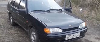
02/28/2022 159 264 117 VAZ 2115
Author: Ivan Baranov
Following the example of foreign automobile companies, it introduces advanced technologies into its vehicles. One such example is an on-board computer, designed to detect a malfunction in the machine using a digital code. We invite you to find out how the on-board computer of the VAZ 2115 is diagnosed - the error codes will also be deciphered in this article.
[Hide]
VAZ (LADA) errors via OBDI protocol. Self-diagnosis.
1 — Malfunction of the engine control unit.
2 — The voltage in the on-board network is too high.
3 — Malfunction in the electrical circuit of the fuel level sensor.
4 — Malfunction in the electrical circuit of the antifreeze controller.
5 — Error in external temperature controller.
6 — Overheating of the engine (power unit)
7 — Emergency oil pressure in the engine.
8 — The voltage in the vehicle's electrical network is too low.
9 — Low battery level (battery is discharged)
12 — Malfunction in the electrical circuit of the malfunction indicator located on the instrument panel.
13 — No data (loss of communication) from the oxygen sensor (lambda probe)
14 — High signal level of the coolant temperature sensor (antifreeze).
15 — Malfunction in the electrical circuit of the coolant temperature controller.
16 — Increased voltage in the vehicle’s electrical network
17 — Low voltage in the on-board network
19 — Malfunction in the electrical circuit of the crankshaft position sensor.
21 — Malfunction in the throttle position regulator.
22 — Low signal level of the throttle position sensor
23 — High signal level of the intake air temperature sensor
24 — Malfunction in the electrical circuit of the vehicle speed sensor.
25 — Low signal level of the intake air temperature sensor
27 — Incorrect signal from the exhaust gas system sensor
28 — Incorrect signal from the exhaust gas system sensor
33 — Malfunction in the electrical circuit of the air flow meter
34 — Malfunction in the electrical circuit of the air flow meter
35 — The ECU has detected a deviation in idle speed
41 — Incorrect signal coming from the phase regulator
42 — Malfunction in the electrical circuit of the electronic ignition system
43 — Incorrect signal coming from the knock sensor
44 — The mixture in the engine cylinders is too lean or rich
45 — The mixture in the engine cylinders is too lean or rich
49 — Vacuum leak
51 — Malfunction of one of the memory modules of the control unit - RAM or PROM
52 — Malfunction of one of the memory modules of the control unit - RAM or PROM
53 — Incorrect signal coming from the exhaust gas sensor
54 — No signal from the octane corrector regulator
55 — Poor air-fuel mixture at low load on the car engine
61 — Malfunction in the electrical circuit of the oxygen sensor (lambda probe)
E - Determining an error in a data packet stored in EEPROM
Car diagnostics
Of course, it is impossible to detect a malfunction in the operation of a vehicle without diagnostics. This can be done using special equipment, which can be found at every specialized service station. But you can also check your car for faults on your own. Note that when checking the car yourself, the error codes will not be the same as when diagnosing on the equipment.
Car VAZ 2115 tuning
So, how can you independently diagnose the state of the VAZ 2115 on-board computer? This question came to the mind of every owner of these car models. Now we will tell you about this in more detail. But diagnosing the car is half the battle, because the resulting combinations of faults also need to be deciphered.
Self-diagnosis of VAZ:
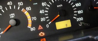
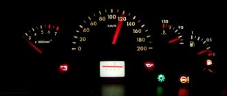
- Find the odometer button on the instrument panel. You need to clamp it down.
- Then turn the ignition key to position 1.
- Having done this, the odometer button will need to be released.
- When you release the button, the arrows on the instrument panel will start jumping.
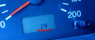
- Press and release the odometer button again. Numbers will appear on the speedometer indicating the firmware version of the on-board computer.
- Finally, hold and release the odometer button for the third time and you can see the fault combination. In the case of self-checking, error codes will be presented in two-digit form, in contrast to diagnostics on equipment, where faults are presented in four-digit form.
Pressing the odometer button to carry out self-diagnosis of the VAZ 2115
VAZ (LADA) errors via OBDII protocol
Fuel system and air supply
P0000-P0099, P0100-P0199, P0200-P0299
P0030 - Malfunction in the electrical circuit of the oxygen sensor heater
P0031 - Oxygen Sensor Heater Circuit Low Voltage
P0032 - Oxygen Sensor Heater Circuit High Voltage
P0100 - Malfunction in the electrical circuit of the mass air flow sensor (MAF)
P0101 - Incorrect operation of the mass air flow sensor (MAF)
P0102 - Low signal level of the mass air flow sensor (MAF)
P0103 - High signal level of the mass air flow sensor (MAF)
P0112 - Intake air temperature sensor signal low
P0113 - Intake air temperature sensor signal high
P0114 - Insufficient contact of the electrical circuit of the intake air temperature sensor
P0115 - Malfunction in the electrical circuit of the coolant temperature sensor
P0116 - Incorrect operation of the coolant temperature sensor
P0117 - Low signal level from the coolant temperature sensor
P0118 - High signal level from the coolant temperature sensor
P0119 - Insufficient contact of the electrical circuit of the coolant temperature sensor
P0120 - Malfunction in the electrical circuit of the throttle position sensor
P0121 - Incorrect operation of the throttle position sensor
P0122 - Low signal level from the throttle position sensor
P0123 - High signal level from the throttle position sensor
P0130 - Malfunction in the electrical circuit of the oxygen sensor
P0131 - Oxygen sensor voltage low
P0132 - Oxygen Sensor Voltage High
P0133 - Low speed oxygen sensor
P0134 - No response from oxygen sensor
P0135 - Heated Oxygen Sensor Circuit Malfunction
P0171/171 – Air/fuel mixture too lean
P0201 - Malfunction in the electrical circuit of injector 1
P0202 - Malfunction in the electrical circuit of injector 2
P0203 - Malfunction in the electrical circuit of injector 3
P0204 - Malfunction in the electrical circuit of injector 4
P0222 - Throttle Position Sensor 2 Low
Ignition system
P0300-P0399
P0300/300 – Multiple misfires (ignition)
P0301 / 301 - Misfire (ignition) in cylinder No. 1
P0302 / 302 - Misfire (ignition) in cylinder No. 2
P0303 / 303 - Misfire (ignition) in cylinder No. 3
P0304 / 304 - Misfire (ignition) in cylinder No. 4
P0326 - Incorrect operation of the knock sensor
P0327/327 – Knock sensor signal low
P0328/328 – Knock sensor signal high
P0335 / 335 - Malfunction in the crankshaft position sensor electrical circuit
P0336 - Incorrect operation of the crankshaft position sensor
P0337 - Low signal level from the crankshaft position sensor
P0338 - High signal level from the crankshaft position sensor
P0343/343 – Camshaft Position Sensor High Signal
P0351 - Malfunction in the electrical circuit of the ignition coil "A"
P0352 - Malfunction in the electrical circuit of the ignition coil "B"
P0363 - Misfire (ignition) - lack of fuel supply
Emission control
P0400-P0499
P0422 / 422 - Low catalyst performance
P0441/441 - Evaporative Emission System - Flow Incorrect
P0442 - Evaporative Emission System - Minor Leak
P0443 - Malfunction in the electrical circuit of the evaporative emission solenoid valve
P0444 - Evaporative Emission Solenoid Valve Circuit Open
P0480 - Malfunction in the electrical circuit of the engine cooling fan
P0485 - Malfunction in the electrical circuit of the engine cooling fan
Speed and idle control
P0500-P0599
P0500 - Malfunction in the electrical circuit of the vehicle speed sensor
P0501/501 – Vehicle Speed Sensor Malfunction
P0504 / 504 - Incorrect brake pedal position sensor signal
P0505 - Malfunction in the idle speed control system
P0506 - Engine idle speed below acceptable values
P0507 - Engine idle speed is higher than permissible values
P0511 - Idle Air Bypass Control Circuit Malfunction
P0560 - System voltage (on-board network) - malfunction
P0562 - Low voltage in the system (on-board network)
P0563 - High voltage in the system (on-board network)
Electronic control unit (ECU) and its subsystems
P0600-P0699
P0601 - Electronic Engine Control Module - Memory Checksum Error
P0603/603 – Engine control module external RAM module error
P0615 - Starter relay circuit malfunction
P0628 - Fuel Pump Control - Low Signal
P0650 - Malfunction indicator circuit malfunction
Transmission
P0700-P0799, P0800-P0899, P0900-P0999
P0830 / 830 - Malfunction in the electrical circuit of the clutch pedal position sensor
Other errors
P1135 - Malfunction in the electrical circuit of the oxygen sensor heater
P1140 - Measured engine load differs from calculated load
P1141 - Malfunction in the electrical circuit of the oxygen sensor heater installed after the converter
P1301 - Cylinder 1 - Converter critical misfire detected
P1302 - Cylinder 2 - Converter critical misfire detected
P1303 - Cylinder 3 - Converter critical misfire detected
P1304 - Cylinder 4 - Converter critical misfire detected
P1335 - Throttle Actuator Control Monitoring - Position Out of Range
P1336 - Controller type does not match standard
P1425 - Malfunction in the electrical circuit of the canister purge control valve
P1426 - Malfunction in the electrical circuit of the canister purge valve
P1513 - Malfunction in the electrical circuit of the idle speed sensor
P1514 - Malfunction in the electrical circuit of the idle speed sensor
P1541 - Fuel pump relay control circuit malfunction
P1545 - Throttle position is out of operating range
P1570 - Immobilizer control circuit malfunction
P1578 - Invalidity of throttle valve relearning results
P1600 - No communication with immobilizer
P1602 - Interruption of on-board network voltage
P1603 - Malfunction of the internal microprocessor memory module
P1612 - Electronic control unit processor memory reset error
P1617 - High signal level from rough road sensor
P1620 - Incorrect operation of the internal memory module of the control unit
P1621 - Incorrect operation of the control unit RAM module
P2020 - Incorrect operation of the drive position sensor of the intake manifold geometry changing system
P2122 - Low signal level from the gas pedal position sensor
P2127 - Low signal level from the gas pedal position sensor
P2135 - Accelerator Pedal Position Sensor - Voltage Correlation
P2138 - Accelerator pedal sensor voltage correlation
P2187 - Air/fuel mixture too lean at idle
P2188 - Air/fuel mixture too rich at idle
P2302 - Malfunction in the electrical circuit of the ignition coil "A"
P2305 - Malfunction in the electrical circuit of the ignition coil "B"
How to fix the problem
After diagnosis, the problem should be repaired. When reading a signal, it is necessary to check the circuit and devices following it. The most accurate method is to replace the damaged part with a known good one (new). This will eliminate the possibility of incorrect repairs. If the device is in working condition, the lines are checked; usually a primitive test is sufficient. However, if the control unit or relay fails, you will need a special tester and the ability to use it.
Separately, it is necessary to take into account that factory terminals and blocks become loose and oxidize over time. If the contact on the hitch deteriorates, the on-board computer or laptop program will say that the part is damaged, even if it is not.
You can prevent this from happening in the following way.
- Check the condition of the connectors once every 5000 km. The pads should sit in place tightly, without play. If necessary, elements must be replaced with new ones.
- Check plug connectors two to three times a year for oxidation. Oxides reduce the flow of electricity through on-board wiring, which leads to incorrect display of information.
- Experts recommend purchasing and using oil for electrical terminals. The liquid is similar in composition to transformer lubricants. The formula prevents water and oxygen from reaching metals, which prevents them from rusting.
Important!
You can diagnose VAZ 2114 error codes on the instrument panel and ECU yourself, only if you understand the essence of the process. If you don’t have confidence in your own abilities, it is recommended to contact a qualified technician.
Decoding fault codes VAZ 2115 8 valves
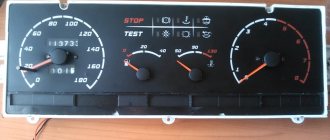
Depending on the type of device, certain symbols and numbers are displayed on the dashboard, indicating the presence of an error. In self-diagnosis mode, the data is reflected on the instrument panel in the square of the on-board display. A one or two-digit number indicating the problem is indicated here.
If diagnostics are performed by a third-party device, error codes are displayed on the computer display and are represented by an alphanumeric code consisting of 5 characters, where the first indicates the area of failure. The second sign indicates the factory code, the third specifies the problem circuit. The last 2 digits indicate the problem itself.
The complete table of faults for the VAZ 2115 contains more than a thousand names and encodings. The following are only the most common problems.
Error 01
The microprocessor has failed. There is a firmware glitch. Repair consists of replacing or reconfiguring the module.
Error code 2
The fuel level sensor in the tank is damaged or stuck. Disassemble the system and inspect the sensor for damage.
Fault 3
It is a combination of errors No. 2 and 1. Troubleshooting is indicated above.
Breakdown 4
Excessively high voltage in the network. The reason lies in a short circuit in the line.
Error 8: Lada 2115 8 valves
The problem arises when the car has an injector. The causes and elimination of the malfunction are completely opposite to point number 4. Here we are talking about a critical voltage drop in the on-board network, which is caused by battery failure or damage to the generator set.
Error 10
This means that when the engine is under high load, a lean fuel mixture enters the engine. The behavior causes a malfunction of the injector or throttle valve.
Breakdown 11
Indicates the presence of two or more problems at the same time. The number is obtained by adding the codes 8 and 3.
Fault 12
The check engine light is damaged or there is a problem with its wiring. It can be eliminated by studying the entire highway followed by repairs.
Error 14
The coolant temperature sensor is faulty or not working correctly. The situation can only be corrected by completely replacing the part - the sensor cannot be repaired.
Error 19: what needs to be changed
DPKV does not work correctly or there are problems with the marks matching. There are 2 fix options.
- Repair and replacement of the sensor itself.
- Establishing the correct alignment of marks and parts of the design provided by the engine manufacturer.
Error 20: decryption
Represents a combination of several errors at the same time. To understand the essence of the problem, perform detailed computer diagnostics.
Breakdown 26
A combination of three or more problems. The machine displays something like this when there are a lot of breakdowns.
Fault 44
The fuel mixture is too lean at low load or idle. Check the fuel lines for stray air leaks.
Code P0036
The low speed controller is faulty. A complete diagnostic of the module is required.
Error codes 0038
The last problem on the list, which is a combination of several faults. It is required to carry out computer diagnostics of the circuit.