VAZ error codes and their interpretation
Dear friends, since carburetor VAZs are already history, and the vast majority of VAZ owners, from classics to grants, are happy owners of injection engines, this does not eliminate the need to diagnose the engine and eliminate certain problems. And if earlier we simply changed spark plugs in any incomprehensible situation, adjusted the ignition and cleaned or purged the carburetor, then in an injection engine everything is somewhat more complicated, since everything is controlled by the ECU - the brains of the car. Many people acquire on-board computers, but not every bookmaker knows how to decipher errors ; most bookmakers simply show the error code , if there is one, and the car owner (or a diagnostician) will have to decipher this error And since every check error makes it expensive to go to a diagnostician, and the choice of bookmakers in the budget segment is quite large, and almost any driver will be able to purchase this useful device in a car, we are posting VAZ error codes with decoding so that you can easily identify one or another engine error.
Decoding error codes issued by the ECU of VAZ cars
| Code | Decoding |
| P0030 | Oxygen sensor heater before the converter, control circuit open |
| P0031 | Oxygen sensor heater before converter, control circuit short to ground |
| P0032 | Heater of the oxygen sensor to the converter, short circuit of the control circuit to the board. net |
| P0036 | Oxygen sensor heater after the converter, control circuit open |
| P0037 | Oxygen sensor heater after converter, control circuit short to ground |
| P0038 | Heater of the oxygen sensor after the converter, short circuit of the control circuit to the board. net |
| P0102 | Mass Air Flow Sensor Circuit Low Signal |
| P0103 | Mass Air Flow Sensor Circuit High Signal |
| P0112 | Air temperature sensor circuit low signal |
| P0113 | Air temperature sensor circuit high signal |
| P0116 | Coolant temperature sensor circuit, signal out of range |
| P0117 | Coolant Temperature Sensor Circuit Low Signal |
| P0118 | Coolant Temperature Sensor Circuit High |
| P0122 | Throttle Position Sensor Circuit Low Signal |
| P0123 | Throttle Position Sensor Circuit High |
| P0130 | The oxygen sensor before the converter is faulty |
| P0131 | Oxygen sensor circuit to converter, low output level |
| P0132 | Oxygen sensor circuit to converter, high output level |
| P0133 | Oxygen sensor circuit to the converter, slow response to changes in mixture composition |
| P0134 | The oxygen sensor circuit to the converter is inactive |
| P0136 | The oxygen sensor after the converter is faulty |
| P0137 | Oxygen sensor circuit after the converter, low signal level |
| P0138 | Oxygen sensor circuit after the converter, high signal level |
| P0140 | The oxygen sensor circuit after the converter is inactive |
| P0141 | Oxygen sensor after converter, heater faulty |
| P0171 | Fuel system too lean |
| P0172 | Fuel system too rich |
| P0201 | Cylinder 1 injector, control circuit open |
| P0202 | Cylinder 2 injector, control circuit open |
| P0203 | Cylinder 3 injector, control circuit open |
| P0204 | Cylinder 4 injector, control circuit open |
| P0217 | Engine temperature is higher than permissible |
| P0230 | Fuel pump relay circuit malfunction |
| P0261 | Cylinder 1 injector control circuit short to ground |
| P0263 | Injector driver fault 1 |
| P0264 | Cylinder 2 injector control circuit short to ground |
| P0266 | Faulty injector driver 2 |
| P0267 | Cylinder 3 injector control circuit short to ground |
| P0269 | Injector 3 driver malfunction |
| P0270 | Cylinder 4 injector control circuit short to ground |
| P0262 | Cylinder 1 injector, control circuit shorted to on-board power supply |
| P0265 | Cylinder 2 injector, control circuit shorted to on-board power supply |
| P0268 | Cylinder 3 injector, control circuit shorted to on-board power supply |
| P0271 | Cylinder 4 injector, control circuit shorted to on-board power supply |
| P0272 | Injector 4 driver malfunction |
| P0300 | Random/multiple misfires detected |
| P0301 | Cylinder 1, misfire detected |
| P0302 | Cylinder 2, misfire detected |
| P0303 | Cylinder 3, misfire detected |
| P0304 | Cylinder 4, misfire detected |
| P0326 | Knock sensor circuit, signal output out of acceptable range |
| P0327 | Knock Sensor Circuit Low Signal |
| P0328 | Knock Sensor Circuit High Signal |
| P0335 | Crankshaft position sensor circuit is faulty |
| P0336 | Crankshaft position sensor circuit, signal out of range |
| P0337 | Crankshaft position sensor, short to ground |
| P0338 | Crankshaft position sensor, open circuit |
| P0340 | Camshaft position sensor malfunction |
| P0342 | Phase Sensor Circuit Low Signal |
| P0343 | Phase sensor circuit, high signal level |
| P0346 | Phase sensor circuit, signal output out of acceptable range |
| P0351 | Ignition coil of cylinder 1 (1-4), control circuit open |
| P0352 | Ignition coil of cylinder 2 (2-3), control circuit open |
| P0353 | Ignition coil of cylinder 3, control circuit open |
| P0354 | Ignition coil of cylinder 4, control circuit open |
| P0363 | Misfires detected, fuel supply to idle cylinders turned off |
| P0422 | Neutralizer efficiency below threshold |
| P0441 | Gasoline vapor recovery system, incorrect air flow through the canister purge valve |
| P0444 | Canister purge valve, control circuit open |
| P0445 | canister purge valve, control circuit short to ground or on-board network |
| P0480 | Fan relay, control circuit open |
| P0481 | Cooling Fan 2 Circuit Malfunction |
| P0500 | Vehicle speed sensor is faulty |
| P0506 | Idle system, low engine speed |
| P0507 | Idle system, high engine speed |
| P0511 | Idle air control control circuit faulty |
| P0560 | On-board network voltage is below the system operability threshold |
| P0562 | On-board voltage, low level |
| P0563 | On-board voltage, high level |
| P0601 | Engine management system controller, ROM checksum error |
| P0615 | Additional starter relay, control circuit open |
| P0616 | Additional starter relay, control circuit short to ground |
| P0617 | Additional starter relay, control circuit closed to on-board network |
| P0627 | Fuel pump relay, control circuit open |
| P0628 | Fuel pump relay, control circuit short to ground |
| P0629 | Fuel pump relay, control circuit shorted to on-board network |
| P0645 | A/C compressor clutch relay, control circuit open |
| P0646 | A/C compressor clutch relay, control circuit short to ground |
| P0647 | Air conditioning compressor clutch relay, control circuit shorted to board. net |
| P0650 | Malfunction indicator lamp, control circuit faulty |
| P0654 | Instrument cluster tachometer, control circuit faulty |
| P0685 | Main relay, control circuit open |
| P0686 | Main relay, control circuit short to ground |
| P0687 | Main relay, control circuit shorted to on-board network |
| P0691 | Fan relay, control circuit short to ground |
| P0692 | Fan relay, control circuit shorted to on-board power supply |
| P1102 | Oxygen Sensor Heater Resistance Low |
| P1115 | Faulty oxygen sensor heating circuit |
| P1123 | Rich mixture at idle |
| P1124 | Lean mixture at idle |
| P1127 | Rich mixture at Part Load |
| P1128 | Lean mixture in Partial Load mode |
| P1135 | Oxygen sensor heater circuit 1 open, short circuit |
| P1136 | Rich mixture in Low Load mode |
| P1137 | Lean mixture in Low Load mode |
| P1140 | Measured load differs from calculation |
| P1141 | Malfunction of the oxygen sensor heater 1 after the converter |
| P1171 | Low level CO potentiometer |
| P1172 | High level CO potentiometer |
| P1301 | Cylinder 1, misfire detected, critical for converter |
| P1302 | Cylinder 2, misfire detected, critical for converter |
| P1303 | Cylinder 3, misfire detected, critical for converter |
| P1304 | Cylinder 4, misfire detected, critical for converter |
| P1386 | Knock Channel Test Error |
| P1410 | Canister purge valve control circuit short circuit to +12V |
| P1425 | Canister purge valve control circuit short circuit to ground |
| P1426 | Canister purge valve control circuit open |
| P1500 | Open circuit in the fuel pump relay control circuit |
| P1501 | Short circuit to ground of the fuel pump relay control circuit |
| P1502 | Short circuit to +12V fuel pump relay control circuit |
| P1509 | Idle air control control circuit overload |
| P1513 | Idle air control circuit short circuit to ground |
| P1514 | Idle air control circuit short circuit to +12V, open |
| P1541 | Fuel pump relay control circuit open |
| P1570 | Immobilizer, circuit faulty |
| P1602 | Engine control system controller, power supply loss |
| P1606 | Rough road sensor circuit, signal out of acceptable range |
| P1616 | Rough Road Sensor Circuit Low Signal |
| P1617 | Rough Road Sensor Circuit High Signal |
| P2301 | Ignition coil of cylinder 1 (1-4), control circuit shorted to board. net |
| P2303 | Ignition coil of cylinder 2 (2-3), control circuit shorted to board. net |
| P2305 | Ignition coil of cylinder 3, control circuit shorted to board. net |
| P2307 | Ignition coil of cylinder 4, control circuit shorted to board. net |
Description of fault codes for controllers ME17.9.7 and M74
| Part (system) | Code | Control checks | Malfunction detection condition |
| Mass air flow sensor | P0101 | Validity check | Air flow is out of range |
| P0102 | Low value check | The signal period is greater than the upper threshold value | |
| P0103 | High value check | The signal period is less than the lower threshold value | |
| Intake air temperature sensor | P0112 | Low value check | Voltage is less than the lower threshold value |
| P0113 | High value check | Voltage is greater than the upper threshold value | |
| Coolant temperature sensor | P0116 | Validity check | Temperature is less than calculated value |
| P0117 | Low value check | Voltage is less than the lower threshold value | |
| P0118 | High value check | Voltage is greater than the upper threshold value | |
| Throttle Position Sensors | P2135 | Checking the mismatch between the signals of two sensors | The sensor voltages differ by the threshold value |
| P0122 | Low value check (sensor 1) | Voltage is less than the lower threshold value | |
| P0123 | High value check (sensor 1) | Voltage is greater than the upper threshold value | |
| P0222 | Low value check (sensor 2) | Voltage is less than the lower threshold value | |
| P0223 | High value check (sensor 2) | Voltage is greater than the upper threshold value | |
| Accelerator pedal position sensors | P2138 | Checking the mismatch between the signals of two sensors | The sensor voltages differ by the threshold value |
| P2122 | Low value check (sensor 1) | Voltage is less than the lower threshold value | |
| P2123 | High value check (sensor 1) | Voltage is greater than the upper threshold value | |
| P2127 | Low value check (sensor 2) | Voltage is less than the lower threshold value | |
| P2128 | High value check (sensor 2) | Voltage is greater than the upper threshold value | |
| Injectors | P0201 | Checking the control circuit for open circuit | Driver diagnostics |
| P0202 | |||
| P0203 | |||
| P0204 | |||
| P0261 | Checking the short circuit of the control circuit to ground | ||
| P0264 | |||
| P0267 | |||
| P0270 | |||
| P0262 | Checking the short circuit of the control circuit on the on-board network | ||
| P0265 | |||
| P0268 | |||
| P0271 | |||
| Control oxygen sensor | P0130 | Checking signal circuit integrity | Voltage is less than the lower threshold value or greater than the upper threshold value |
| P0131 | Low value check | Voltage is less than the lower threshold value | |
| P0132 | High value check | Voltage is greater than the upper threshold value | |
| P0133 | Checking for slow response | The signal period is greater than the threshold value | |
| P0134 | Activity check | Voltage is less than the upper threshold value and greater than the lower threshold value | |
| P0030 | Heater circuit open circuit check | Driver diagnostics | |
| P0031 | Checking the short circuit of the heater circuit to ground | ||
| P0032 | Checking the short circuit of the heater circuit to the on-board network | ||
| Diagnostic oxygen sensor | P0136 | Checking signal circuit integrity | Voltage is less than the lower threshold value or greater than the upper threshold value |
| P0137 | Low value check | Voltage is less than the lower threshold value | |
| P0138 | High value check | voltage is greater than the upper threshold value | |
| P0140 | Activity check | Voltage is less than the upper threshold value and greater than the lower threshold value | |
| P0036 | Heater circuit open circuit check | Driver diagnostics | |
| P0037 | Checking the short circuit of the heater circuit to ground | ||
| P0038 | Checking the short circuit of the heater circuit to the on-board network | ||
| Fuel supply system | P0171 | Checking the leanness of the mixture | Fuel correction coefficients are greater than the upper threshold value |
| P2187 | Checking the lean mixture (idling) | ||
| P0172 | Checking the richness of the mixture | Fuel correction coefficients are less than the lower threshold value | |
| P2188 | Checking the richness of the mixture (idling) | ||
| Engine overheating | P0217 | Engine temperature monitoring | Engine temperature above threshold |
| Misfire for toxicity | P0300 | Checking for misfires affecting toxicity | The number of misfires is greater than the threshold value |
| P0301 | |||
| P0302 | |||
| P0303 | |||
| P0304 | |||
| Misfire to protect the converter | P0363 | Checking for misfires affecting the converter | The number of misfires is greater than the threshold value |
| P1301 | |||
| P1302 | |||
| P1303 | |||
| P1304 | |||
| Knock sensor | P0326 | Low value check | Normalized signal level is outside the acceptable range |
| P0327 | Low value check | Normalized signal level is less than the lower threshold value | |
| P0328 | High value check | Normalized signal level is greater than the upper threshold value | |
| Crankshaft position sensor | P0335 | Checking for signal presence | Change in air flow in the absence of a signal from the crankshaft position sensor above the threshold value |
| P0336 | Validity check | The controller counts the wrong number of teeth per revolution of the crankshaft | |
| Camshaft position sensor | P0340 | Checking for signal presence | The sensor signal does not change when the engine is running |
| P0342 | Low value check | Low sensor signal for several crankshaft revolutions | |
| P0343 | High value check | High sensor signal for several crankshaft revolutions | |
| Ignition coils | P0351 | Checking for open circuit | Primary circuit current is less than threshold value |
| P0352 | |||
| P2301 | Checking the short-circuit circuit on the on-board network | The primary circuit current is greater than the threshold value | |
| P2304 | |||
| Neutralizer | P0422 | Determining the capacity of stored oxygen by comparing the amplitude range of the control and diagnostic oxygen sensors | The aging coefficient of the neutralizer is greater than the upper threshold value |
| Canister purge valve | P0441 | Functional check | The response of the idle control system is greater or less than the threshold value |
| P0459 | Checking the short-circuit circuit on the on-board network | Driver diagnostics | |
| P0458 | Checking the short circuit to ground | ||
| P0444 | Checking for open circuit | ||
| Cooling fan relay 1 | P0692 | Checking the short-circuit circuit on the on-board network | Driver diagnostics |
| P0691 | Checking the short circuit to ground | ||
| P0480 | Checking for open circuit | ||
| Cooling fan relay 2 | P0694 | Checking the short-circuit circuit on the on-board network | Driver diagnostics |
| P0693 | Checking the short circuit to ground | ||
| P0481 | Checking for open circuit | ||
| Cooling Fan | P0485 | Checking the supply voltage of cooling fans | Voltage is less than the lower threshold Voltage is greater than the upper threshold |
| Vehicle speed sensor | P0500 | Checking for signal presence | Vehicle speed is less than the threshold value |
| Brake pedal sensor | P0504 | Checking the sensor signal mismatch time | Sensor signals change inconsistently |
| Onboard voltage | P0560 | Checking the validity of a value | voltage in circuits Cl. "30" and Cl. “15” differs by the threshold value |
| P0562 | Low value check | Voltage is less than the lower threshold value | |
| P0563 | High value check | Voltage is greater than the upper threshold value | |
| P1602 | Checking the supply voltage | Power failure | |
| Controller | P1640 | Checking EEPROM | EEPROM test error |
| P0601 | Checking the software checksum | Invalid checksum | |
| P0606 | Controller internal checks | ADC is faulty | |
| P2105 | Monitoring module is faulty | ||
| Starter relay | P0615 | Checking for open circuit | Driver diagnostics |
| P0616 | Checking the short circuit to ground | ||
| P0617 | Checking the short-circuit circuit on the on-board network | ||
| Fuel pump relay | P0627 | Checking for open circuit | Driver diagnostics |
| P0628 | Checking the short circuit to ground | ||
| P0629 | Checking the short-circuit circuit on the on-board network | ||
| A/C clutch relay | P0645 | Checking for open circuit | Driver diagnostics |
| P0646 | Checking the short circuit to ground | ||
| P0647 | Checking the short-circuit circuit on the on-board network |
With On-Board Diagnostic (OBD) system
| Code | Malfunction |
| P0105 | Damage to the electrical circuit of the air flow meter sensor |
| P0112 | Low signal level of air temperature sensor |
| P0113 | High level of air temperature sensor signal |
| P0116 | Damage to the electrical circuit of the coolant temperature sensor |
| P0117 | Coolant temperature sensor signal low |
| P0118 | High signal level of the coolant temperature sensor |
| P0121 | Damage to the electrical circuit of the throttle position sensor |
| P0122 | Low throttle position sensor signal |
| P0123 | Throttle position sensor signal high |
| P0130 | Damage to the electrical circuit of the oxygen sensor |
| P0131 | Low oxygen sensor signal |
| P0132 | High signal level of the oxygen sensor |
| P0133 | Slow response of oxygen sensor |
| P0134 | Poor oxygen sensor performance |
| P0135 | Damage to the electrical circuit of the heated oxygen sensor |
| P0136 | Damage to the electrical circuit of the downstream oxygen sensor |
| P0137 | Low signal level of the lower oxygen sensor |
| P0138 | High signal level of the lower oxygen sensor |
| P0141 | Damage to the electrical circuit of the heated oxygen sensor |
| P0201 | Damage to the electrical circuit of the fuel injector of cylinder 1 |
| P0202 | Damage to the electrical circuit of the fuel injector of cylinder 2 |
| P0203 | Damage to the electrical circuit of the fuel injector of cylinder 3 |
| P0204 | Damage to the electrical circuit of the fuel injector of cylinder 4 |
| P0230 | Damage to the electrical circuit of the fuel system |
| P0300 | Random misfires |
| P0301 | Misfire in cylinder 1 |
| P0302 | Misfire in cylinder 2 |
| P0303 | Misfire in cylinder 3 |
| P0304 | Misfire in cylinder 4 |
| P0326 | Damage to the electrical circuit of the knock sensor |
| P0335 | Damage to the electrical circuit of the crankshaft angle sensor |
| P0336 | Random malfunctions of the crankshaft angle sensor |
| P0342 | Low signal level of the camshaft position sensor |
| P0343 | Camshaft position sensor signal high |
| P0422 | Poor catalytic converter efficiency |
| P0444 | Open circuit in the activated carbon canister cleaning valve |
| P0445 | Activated carbon canister cleaning valve circuit shorted |
| P0501 | Damage to the electrical circuit of the vehicle speed sensor |
| P0506 | Reduced idle speed |
| P0507 | Increased idle speed |
| P0562 | Low voltage in the vehicle's on-board network |
| P0563 | Increased voltage in the vehicle's on-board network |
| P0606 | Internal damage to the ECM |
| P1123 | Rich fuel mixture |
| P1124 | Lean mixture |
| P1127 | Long-term over-enrichment of the fuel mixture |
| P1128 | Long-term leanness of the fuel mixture |
| P1510 | The idle air system valve is constantly open due to a short circuit in the valve coil power supply circuit. |
| P1513 | The idle air system valve is constantly open due to a break in the electrical supply circuit to the valve coil |
| P1552 | The idle air system valve is constantly closed due to a short circuit in the valve coil power supply circuit. |
| P1553 | The idle air system valve is constantly closed due to a break in the electrical supply circuit to the valve coil |
| P1529 | Damage to the transmission control unit |
| P1586 | Inappropriate signal received from gearbox |
| P1605 | Damage to the electrical circuit of the acceleration sensor |
| P1606 | Inappropriate signal received from acceleration sensor |
| P1611 | MIL Input Low |
| P1613 | MIL Input High |
| P1610 | Damage to the SMATRA immobilizer |
| P1800 | Damage to the immobilizer antenna |
| P1801 | Damage to the immobilizer pulse transceiver |
| P1803 | ECM signal error |
Without on-board diagnostics (OBD)
| Code | Malfunction |
| P0105 | Damage to the electrical circuit of the air flow meter sensor |
| P0112 | Low signal level of air temperature sensor |
| P0113 | High level of air temperature sensor signal |
| P0116 | Damage to the electrical circuit of the coolant temperature sensor |
| P0117 | Coolant temperature sensor signal low |
| P0118 | High signal level of the coolant temperature sensor |
| P0121 | Damage to the electrical circuit of the throttle position sensor |
| P0122 | Low throttle position sensor signal |
| P0123 | Throttle position sensor signal high |
| P0130 | Damage to the electrical circuit of the oxygen sensor |
| P0131 | Low oxygen sensor signal |
| P0132 | High signal level of the oxygen sensor |
| P0133 | Slow response of oxygen sensor |
| P0134 | Poor oxygen sensor performance |
| P0135 | Damage to the electrical circuit of the heated oxygen sensor |
| P0230 | Damage to the electrical circuit of the fuel system |
| P0201 | Damage to the electrical circuit of the fuel injector of cylinder 1 |
| P0202 | Damage to the electrical circuit of the fuel injector of cylinder 2 |
| P0203 | Damage to the electrical circuit of the fuel injector of cylinder 3 |
| P0204 | Damage to the electrical circuit of the fuel injector of cylinder 4 |
| P0326 | Damage to the electrical circuit of the knock sensor |
| P0335 | Damage to the electrical circuit of the crankshaft angle sensor |
| P0336 | Random malfunctions of the crankshaft angle sensor |
| P0342 | Low signal level of the camshaft position sensor |
| P0343 | Camshaft position sensor signal high |
| P0501 | Damage to the electrical circuit of the vehicle speed sensor |
| P0506 | Reduced idle speed |
| P0507 | Increased idle speed |
| P0562 | Low voltage in the vehicle's on-board network |
| P0563 | Increased voltage in the vehicle's on-board network |
| P0606 | Internal damage to the ECM |
| P1123 | Rich fuel mixture |
| P1124 | Lean mixture |
| P1127 | Long-term over-enrichment of the fuel mixture |
| P1128 | Long-term leanness of the fuel mixture |
| P1510 | The idle air system valve is constantly open due to a short circuit in the valve coil power supply circuit. |
| P1513 | The idle air system valve is constantly open due to a break in the electrical supply circuit to the valve coil |
| P1552 | The idle air system valve is constantly closed due to a short circuit in the valve coil power supply circuit. |
| P1553 | The idle air system valve is constantly closed due to a break in the electrical supply circuit to the valve coil |
| P1586 | Inappropriate signal received from gearbox |
| P1610 | Damage to the SMATRA immobilizer |
| P1800 | Damage to the immobilizer antenna |
| P1801 | Damage to the immobilizer pulse transceiver |
| P1803 | ECM signal error |
| P1805 | Damage to EEPROM |
| P1765 | Torque reduction circuit damaged |
Diagnostic Trouble Codes (1.8/2.0L I4)
With On-Board Diagnostic (OBD) system
| Code | Malfunction |
| P0010 | Camshaft Position Actuator Circuit (Group 1) |
| P0030 | Damage to the oxygen sensor heater circuit (group 1, sensor 1) |
| P0036 | Damage to the oxygen sensor heater circuit (group 1, sensor 2) |
| P0075 | Damage to the intake valve control solenoid circuit (group 1) |
| P0076 | Intake Valve Control Solenoid Circuit Low (Bank 1) |
| P0077 | Intake Valve Control Solenoid Circuit High (Group 1) |
| P0105 | Damage to the electrical circuit of the absolute air pressure sensor |
| P0106 | Malfunction of the absolute air pressure sensor |
| P0110 | The electrical circuit of the air temperature sensor is faulty |
| P0115 | Damage to the electrical circuit of the coolant temperature sensor |
| P0116 | Violation of the amplitude/characteristics of the coolant temperature sensor |
| P0120 | Damage to the electrical circuit of the throttle position sensor |
| P0121 | Violation of the amplitude/characteristics of the throttle position sensor |
| P0125 | Low coolant temperature |
| P0130 | Damage to the electrical circuit of the oxygen sensor (group 1, sensor 2) |
| P0132 | Oxygen sensor signal high (group 1, sensor 2) |
| P0133 | Slow response of oxygen sensor (group 1, sensor 1) |
| P0139 | Slow response of oxygen sensor (group 1, sensor 2) |
| P0134 | Poor oxygen sensor performance (group 1, sensor 1) |
| P0135 | Damage to the electrical circuit of the heated oxygen sensor (group 1, sensor 1) |
| P0136 | Damage to the electrical circuit of the downstream oxygen sensor (group 1, sensor 2) |
| P0140 | Low efficiency of the oxygen sensor (group 1, sensor 2) |
| P0141 | Damage to the electrical circuit of the heated oxygen sensor (group 1, sensor 2) |
| P0170 | Fuel system damage (group 1) |
| P0196 | Violation of the amplitude/characteristics of the engine oil temperature sensor |
| P0197 | Low signal from engine oil temperature sensor |
| P0198 | Engine oil temperature sensor signal high |
| P0201 | Damage to the electrical circuit of the fuel injector of cylinder 1 |
| P0202 | Damage to the electrical circuit of the fuel injector of cylinder 2 |
| P0203 | Damage to the electrical circuit of the fuel injector of cylinder 3 |
| P0204 | Damage to the electrical circuit of the fuel injector of cylinder 4 |
| P0230 | Damage to the electrical circuit of the fuel system |
| P0300 | Random misfires |
| P0301 | Misfire in cylinder 1 |
| P0302 | Misfire in cylinder 2 |
The codes shown in brackets () are only applicable to vehicles equipped with an immobilizer.
Without on-board diagnostics (OBD)
| Code | Malfunction |
| P0010 | Camshaft Position Actuator Circuit (Group 1) |
| P0075 | Damage to the intake valve control solenoid circuit (group 1) |
| P0105 | Damage to the electrical circuit of the absolute air pressure sensor |
| P0110 | The electrical circuit of the air temperature sensor is faulty |
| P0115 | Damage to the electrical circuit of the coolant temperature sensor |
| P0116 | Violation of the amplitude/characteristics of the coolant temperature sensor |
| P0120 | Damage to the electrical circuit of the throttle position sensor |
| P0130 | Damage to the electrical circuit of the oxygen sensor (group 1, sensor 2) |
| P0132 | Oxygen sensor signal high (group 1, sensor 2) |
| P0134 | Poor oxygen sensor performance (group 1, sensor 1) |
| P0135 | Damage to the electrical circuit of the heated oxygen sensor (group 1, sensor 1) |
| P0196 | Violation of the amplitude/characteristics of the engine oil temperature sensor |
| P0197 | Low signal from engine oil temperature sensor |
| P0198 | Engine oil temperature sensor signal high |
| P0201 | Damage to the electrical circuit of the fuel injector of cylinder 1 |
| P0202 | Damage to the electrical circuit of the fuel injector of cylinder 2 |
| P0203 | Damage to the electrical circuit of the fuel injector of cylinder 3 |
| P0204 | Damage to the electrical circuit of the fuel injector of cylinder 4 |
| P0230 | Damage to the electrical circuit of the fuel system |
| P0325 | Damage to the electrical circuit of knock sensor 1 |
| P0335 | Damage to the electrical circuit of the crankshaft angle sensor |
| P0340 | Damage to the electrical circuit of the camshaft position sensor (CMP) |
| P0443 | Damage to the electrical circuit of the control valve of the fuel vapor recovery system |
| P0501 | Violation of the amplitude/characteristics of the vehicle speed sensor |
| P0560 | Violations in the vehicle's on-board network |
| P0605 | ECM Self-Test Failures |
| P1515 | Incorrect idle air control valve control signal (Coil 1) |
| P1516 | Incorrect idle air control valve control signal (Coil 2) |
| P1602 | Consistent communication failure with the transmission control unit (TCU) |
| P1610 | Lost communication with the anti-theft system |
| P1800 | Damage to the Smatra immobilizer antenna |
| P1801 | Damage to the Smatra immobilizer pulse transceiver |
| P1803 | There is no request from the anti-theft system |
| P1805 | Incompatible data from anti-theft system |
Diagnostics
If you notice that something is wrong with the operation of the Lada Kalina vehicle, then it makes sense to diagnose the car. As a rule, all breakdowns appear immediately after checking the car. You can ask for help in carrying out diagnostics at a service station, where you will pay a certain amount for this service, or you can do everything yourself. Of course, with the help of special equipment there is a greater chance of identifying a malfunction, since when checking independently there is a possibility of obtaining inaccurate data.
So, let's start diagnosing the car ourselves. For this:
- Turn off the ignition.
- Press and hold the daily mileage reset button.
- While holding the button, turn the key in the ignition.
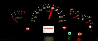
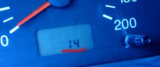
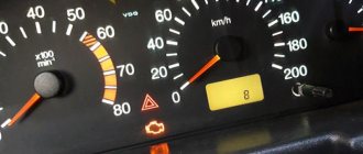
- Having done this, all sensor indicators on the dashboard will light up, and the arrows of the tachometer, speedometer, antifreeze temperature sensor and gasoline level in the fuel tank will move on a scale from zero to maximum. Next, press the button located on the steering column wiper switch. This way you can switch the data on the instrument panel screen. On the first one you can see the process of checking the functionality of the instrument panel. The second will show the version of the software installed in the car, and the third will show combinations of faults.
To check your car for breakdowns, hold down the daily mileage button and hold it while turning on the ignition key. At this time, all arrows will go from zero to maximum.
Then press the button located on the steering column wiper switch. This is done in order to switch the data mode on the instrument panel screen.
To read combinations of faults in a car, you will need the last screen. It will display clear codes. To obtain four-digit combinations of faults, use special equipment or the services of specialists at a service station.
Correction of internal control programs (chip tuning)
Chip tuning
Chip tuning, like ECM modification, also involves changing the factory settings of the software in order to eliminate certain errors in the operation of the software. But the ultimate goal of chip tuning is somewhat different, and is to significantly increase torque and obtain maximum performance from the engine.
The cost that a car owner has to pay to obtain additional power is quite high. Often, as a result of chip tuning, fuel consumption increases significantly and the life of the internal combustion engine decreases.
Taking into account the above information, every car owner should know the answer to two questions before adjusting the injector:
Numbering, ratings and purpose of fuses
Each of the fuses in the VAZ 2107 can serve one or more electrical circuits of the car. If a fuse fails, a specific device or vehicle system (or several) will not receive power. As a result, a particular device becomes inoperable.
Fuse failure is not always the cause of a malfunction. In many cases, a blown fuse is the result of a component or system malfunction. Such cases include:
In the event of a failure of any of the vehicle systems, according to the table below and the fuse location diagram, determine the fuse number and its location in the block. If this fuse is responsible for several systems, you should check the functionality of the other system. If it works correctly, the fuse is most likely good and is not the problem. After this, using a multimeter or other measuring equipment, the functionality of the fuse is checked by measuring its resistance (continuity).
Testing the fuse should only be done on a dismantled (removed) fuse. The resistance of a good fuse is close to zero. In most types of fuses, the thread of its working area is visible through the light or is located outside the body part. You can check the fuse visually, but there are often cases of erroneous inspection when the working area has a microcrack.
Adjustment process
After connecting the laptop to the car’s on-board computer, you have the opportunity to monitor all the parameters of the vehicle in its various systems and see a list of errors that negatively affect the operation of the internal combustion engine. To identify errors, the data obtained in this way must be checked against the basic parameters. In most cases, the program itself indicates a deviation from the norm. If not, then you need to look for the error by its code in the catalog.
After determining the causes of deviations from the norm, errors can be easily eliminated by adjusting certain parameters that affect the operation of the injector.
Location of relay and fuse boxes
The location of the VAZ 2107 fuses and relays is located in the engine compartment, its article number is 2107-3722020-10. It is in an accessible location. In injection cars, an additional relay and fuse block is installed that serves the engine's electronic control unit. It is located under the glove box.
In cars of early years of production, the main relay and fuse box has a different design and arrangement of elements.
Relay on fuse box
The fuse block relays and the VAZ 2107 relays are located in the same fuse block. Their purpose:
Checking the serviceability of the relay can be done using a multimeter. To do this, it is necessary to test the armature winding. Its resistance usually ranges from 50 to 200 ohms. It is safer to test connect the winding to the vehicle's on-board voltage. To do this, the relay must be removed from the relay and fuse block. If one terminal of the winding is connected to the positive terminal of the battery, and the other to the negative terminal, you should hear a characteristic click of the activated relay. The main causes of relay malfunction:
ECU firmware
Firmware update of the electronic control unit is an opportunity to expand the capabilities of your on-board vehicle and make its operation more efficient. It must be said that the first versions of programs for firmware (or chip tuning) of the VAZ 2107 appeared back in 2008.
For most G7 owners, software chip tuning is simply necessary, since this operation allows:
- improve machine performance in all respects;
- optimize the functions of the ECU;
- reduce fuel consumption;
- extend engine life.
ECU firmware must be performed exclusively at a service center and after a complete technical inspection of the motor by specialists. Special service equipment is provided for this procedure. Self-firmware can only be performed if you have experience and modern equipment.
Diagnostic connector
The ECU on the “Seven”, like on other cars, is also equipped with a diagnostic connector. Today, all connectors are manufactured according to the same OBD2 standard. That is, the “on-board vehicle” can be checked for errors and malfunctions using a conventional scanner with a standard cord.
What is it used for?
The OBD2 diagnostic connector is equipped with a certain number of contacts, each of which performs its own function. By connecting the scanner to the ECU connector, you can carry out several diagnostic modes at once with high accuracy:
Where is
The diagnostic connector on the VAZ 2107 is located in the most convenient place for work - under the glove compartment in the cabin under the instrument panel. Thus, there is no need to disassemble the engine compartment mechanisms in order to connect the scanner to the ECU.
Basic engine malfunctions
VAZ 2107 cars are equipped with three main types of power units with a displacement of 1.5, 1.6 and 1.7 liters. The second engine is equipped with a distributed injection system, which differs significantly from carburetor engines. During long-term operation, parts and components of the unit are subject to wear, which can cause the following malfunctions:
Diagnosis of injector or ECU malfunctions is carried out using a special tester, which is available at specialized service stations. Repair and restoration work on the engine is classified as complex and requires high qualifications and special skills.