- seven-pin (7 pin) European-type connectors;
- American-type seven-pin (7 pin) connectors;
- thirteen-pin connectors (13 pin);
- special connectors.
The most common types of sockets have 7 and 13 contacts. In Russia, 7-pin devices are usually used, and 13-pin sockets can be seen on many cars from Europe and the USA. The difference lies in the use of additional contacts necessary to activate fog lights and other electrical components of caravans that are popular abroad.
Rules accepted throughout the world provide for the installation of left/right turn signals and stop signals on trailers for passenger cars. The connection diagram for a passenger car trailer socket depends not only on the number of contacts, but also on the standard of the country, so a trailer with European wiring cannot be connected to a socket with Russian wiring without modification. If you install it without modification, then the right dimensions of the BTS will not light up.
About connection methods and types of trailer connectors
To transport cargo trailers, a special traction coupling device is used, made of a powerful power steel structure, which is attached to the rear of the steel platform by an automobile mechanism.
A towbar connection diagram is required, which will ensure safety and compliance with road accident regulations. Many cars provide additional options for the car with a detachable unit: a tow bar socket and electrical wires connecting the power supply and control of the car with an additional traction device.
Basically, motor transport mechanisms are equipped with these devices as an additional service when purchasing a car. The towbar socket can be connected to the car yourself; pinout of the towbar socket and installation of electrical wiring is not difficult to do yourself. Let's look at the trailer connection diagrams and the pinout of the towbar socket.
There are the following connection diagrams for the towbar socket:
- Regular Russian standard with a socket for seven groups of connecting contacts;
- European and American standard for thirteen detachable connections;
- Special connector.
By the way, in Russia and America they also use a method for connecting a towbar with seven and thirteen connectors. Thirteen connections are used in the main connection of electrical wiring in transportable caravans.
When installing and connecting the control circuit for the rear parking devices of a vehicle, you must follow the rules for connecting the socket for a passenger car trailer, the correctness and sequence of operations when turning it on.
You should not perform such operations by poking at the contacts of light devices; a short circuit may occur or the automatic protection of the vehicle control unit may be triggered. And you cannot connect conductors using the twisting method; a poor-quality connection can create an incorrect command, and the devices will be blocked from turning on.
Modern car circuits are equipped with various electronic devices that use electronics, modules, and matching units. Therefore, an additional special connector is included in the complete set of devices.
In the pinout of a truck trailer socket, conductors are used from conductors with a cross-section of 1.5 or 2 mm, more precisely, 1.5 mm will have a total of 6 conductors, 2 mm will have one wire.
The towbar socket with seven connectors has the following pinout structure:
- left turn signal;
- reverse;
- mass 12V;
- right turn signal;
- right side signal;
- Stop signal;
- left side signal.
The thirteen-pin detachable towbar socket consists of the following equipment:
- left turn indicator;
- rear fog lights;
- weight in the chain 1,2,4-8;
- right turn indicator;
- right side signal;
- Stop signal;
- left side signal;
- reverse signal;
- +12 V constant;
- +12V when the ignition is turned on;
- weight in chain 10;
- Reserve pin;
- weight in chain 9.
Connectors with 13 contacts are characterized by the presence of additional contacts with negative and positive polarity, allowing you to connect additional devices such as cameras, lighting devices, etc.
The detachable connection of the towbar electrical wires with seven and thirteen detachable connections consists of two connecting units: a female socket and a male plug. The towbar socket is mounted on the vehicle next to the towbar mounting point.
The trailer fork is installed with an extended harness of connecting conductors on the trailer in order to create a free docking of the trailer and free installation of electrical wiring.
In cases where a special connector is used in cars with an on-board computer and other electronic devices, it is better to use an electronic coordination unit in the installation of the electrical part of the signal control of the trailer mechanism; in other cases, it is possible to install a manual electrical network for the trailer.
Where to find a trailer hitch
Connecting a trailer socket yourself is a simple procedure if the car owner knows the pinout of the socket and has an idea of how to manage the contacts. To ensure that the trailer is securely fixed and does not create an excessive load on the vehicle, it is recommended to use a towbar.
For most models, this element is included in the basic kit. But for older cars (for example, 1980 and earlier), the presence of a towbar with the ability to connect electrical appliances is unlikely.
To find and use a tow bar, use the manufacturer's instructions. It will indicate what type of fastening is recommended to use when using a trailer, and whether the towbar is included in the package.
What is needed to connect
Before connecting the trailer socket, you need to prepare and buy the necessary material in advance.
The package includes the following equipment:
- Socket cover for tow bar. Please note that there is a cover equipped with a rubber seal. When purchasing, inspect the product for the fit of all casing elements and for the absence of loose housing or contact connections. Pay special attention to the condition of the threaded connection and the fastening of screws to the terminals.
- Wire (one core) with a cross-section of 1.5 sq. mm or more. When purchasing, check the possibility of using it in the electrical wiring of a vehicle.
- Corrugation made of metal or polypropylene. Used to insulate wire harnesses and protect against mechanical damage. The average length is up to 2.5-3.0 meters. Immediately take 20-30 plastic clamps to secure the harnesses.
- Connecting blocks. When choosing, give preference to a model with sockets in which fuses can be installed.
- Tools: set of wrenches, drills and bits, screwdrivers, soldering iron, electrical tape.
The specified equipment is usually sufficient for installation work. If something is missing, the scarce elements can be purchased separately.
What is pinout: definition of the term
Before you try to connect the terminals of the trailer to the car, you should know what the pinout of the trailer socket is. In simple terms, this is a diagram of electrical connectors. It allows you to correctly connect the trailer socket to the electrical socket on the car.
Not all drivers are aware that the pinout of the socket may vary for each make and model of car. In addition, some car enthusiasts change trailer lights, therefore, the pinout of the new socket in this case may also become different.
Most trailers for passenger cars are attached to the vehicle using a towbar. This is a special device that not only allows you to securely fasten the trailer to the body of the car, but also allows you to evenly distribute the load on the rear of the car. To correctly connect the trailer and the vehicle, you need to pay attention to the pinout of the trailer socket.
If the components are not connected correctly, the brake lights, left/right indicators, or other LED commands at the rear of the trailer will not work. This is fraught with possible accidents and problems for the trailer owner who was unable to connect the parts correctly.
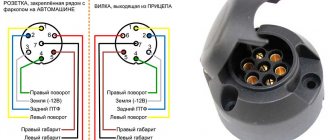
Pinout of 7 pin socket
Below is a drawing showing the wiring of a 7-pin connector (socket and plug). The typical colors of wires for Russian-assembled cars are indicated (color deviations are possible). In European machines, not all contacts on the connector may be used.
Pinout of the 7-pin towbar socket (A) and the corresponding trailer plug (B)
Explanation of the picture:
- Left side turn signal control signal.
- PTF connection (in foreign cars the contact may not be used).
- Weight.
- Starboard turn signal control signal.
- Side lights on the left side.
- Brake light control.
- Side lights on the starboard side
Currently, the 7-pin connector is practically not used in modern foreign cars; 13-pin sockets are installed there. If the trailer has an old type plug, you can connect it to the new Euro connector using a special adapter, which is much easier than changing the connector.
Adapter from 7 to 13 pins
American connecting chips
Many American standards differ from European ones, and trailer hitch socket pinouts are no exception. Here are two types for your reference: 7 and 4 pin connectors.
The 7-pin socket, used in the HOPKINS model range, as well as in other cars (Fig. 8), differs from the European standard practically only in design, which allows, if necessary, replacement with a European analogue.
American 7-pin towbar socket
Designations:
- Connecting side lights.
- +12 V.
- Starboard turning lights.
- Brake light control.
- Weight.
- Turning lights on the left side.
- Reverse signal.
Now let's consider a more complex option - a 4-pin connector (see Fig. 9). If you try to replace it with a European 7-pin socket, problems will arise.
4 pin connector
Designations:
- Weight.
- Control of side lights.
- Left side turn signal and brake light control.
- Starboard turn signal and brake light control.
As you can see, the difficulty is due to the fact that the turn signals and brake lights are controlled along the same line. There are two ways to solve the problem:
- Not entirely correct, but the easiest way: connect directly to the stops and turn signals. Note that in some cars the wiring may not withstand the additional load, so it is better to solve the problem in another way.
- This option is somewhat more complicated, but more correct: you need to completely extend the wiring under the European connector. For example, in a Chevrolet Tahoe, to do this you need to remove the instrument panel, find wires with separate signals for the turn signals and brake lights, connect to them by stretching the electrical wires from the towbar socket through the entire interior of the car. You can make the task a little easier if you take the signal for the brake lights from the rear fender; it is displayed there on almost all cars. In this case, you only need to pull two wires.
Pinout of 13 pin socket
The advantage is reinforced wiring and the number of connectors:
- 1 – yellow – left direction indicator signal;
- 2 – blue – signal from rear fog lights;
- 3 – white – negative signal for contacts 1 to 8;
- 4 – green – right direction indicator signal;
- 5 – brown – size signal on the right side;
- 6 – red – stop light;
- 7 – black – size signal on the left side;
- 8 – pink – reverse lights signal;
- 9 – orange – permanent positive contact;
- 10 – gray – positive contact during ignition;
- 11 – black and white – negative signal for pin 10;
- 12 – white-blue – reserve contact;
- 13 – white-orange – negative signal for pin 9.
Source: 2shemi.ru
Features of connecting trailers Skif-M1, Skif-M2, MZSA and others
When connecting SKIF trailers, you need to be careful, because the pinout in them is somewhat different from the 7-pin circuit according to GOST 9276 and ISO 1724.
Thus, on the second terminal of the Skif-M1, produced from 1981 to 1987, and Skif-M2, produced from 1987 to 1993, the “plus” of the battery is located, and not the rear fog lamp.
Skif-M trailer electrical diagram
Electrical diagram of the Skif-M1 trailer
Electrical diagram of the Skif-M2 trailer
In addition, on MZSA trailers, the dimensions are connected only to the 7th contact. This is done for convenience, so that if necessary you can connect to an old domestic car.
The presence of a “+” battery is a big plus when camping, because it can be used to connect lighting. The designation of the contact group has also changed. Instead of the usual Arabic numerals, Roman numerals are given here.
If we talk about earlier versions of Skif-M, they have more differences.
The following scheme was used here:
- I—STOP signal;
- II - left turn signal;
- III — turn signal indicator light;
- IV - right turn signal;
- V - “plus” of the battery;
- VI — rear dimensions and license plate lights;
- M is mass.
The circuit provides a matching block that relieves the car's turn signal relay.
To operate this element, constant power is required, supplied through the fifth contact from the battery through the outlet.
The old connectors did not separate the side light contacts and they were supplied only through the seventh contact, and the second was considered a spare one.
A lamp was provided there that allowed you to monitor the operation of the trailer and its turn signals.
When connecting an old trailer to a modern type socket, the turn signal on the trailer hitch will only flash when the lights are on. In addition, the fog light (on some models) and the warning light on the dashboard may flash.
In the case of MZSA trailers, nothing comes of the fifth signal. Therefore, if after connection the lights on the tow hitch do not light up, the reason, as a rule, is that the signal is output to the fifth contact, but there will be no signal on the seventh.
A number of trailer manufacturers in the Russian Federation, when installing a reversing lamp, connect it to the fifth terminal, leaving the dimensions with the seventh contact connection.
Pinout of 15 pin connector
This type of connector for connecting trailers and semitrailers is an accepted standard for tractors from almost all manufacturers, including American ones. Considering the requirements for trailers of this class, a standard 13-pin connector is not suitable for powering and controlling their electrical equipment.
Appearance of a 15 pin socket
Matching table for 15-pin connector.
| Pin number | Coloring | Function |
| 1 | Yellow | Left side turn signal |
| 2 | Green | Starboard turn signal |
| 3 | Blue | PTF |
| 4 | White | Earth |
| 5 | Black | Parking lights on the left side |
| 6 | Brown | Side lights on the right side |
| 7 | Red | Brake light control |
| 8 | Pink | Reverse signal |
| 9 | Orange | +24 V |
| 10 | Gray | Transmission of an alarm signal from sensors installed on the brake pads |
| 11 | White-black | Signal from spring brake pressure sensors |
| 12 | White-blue | Bridge lift control |
| 13 | White-red | exchange of information signals |
| 14 | White-green | CAN-H |
| 15 | White-brown | CAN-L |
Connection diagrams (pinout)
When studying the connection diagram for a trailer socket and a car's towbar, it is important to focus on the current GOSTs and rules. They indicate the requirements of government agencies to avoid errors when connecting and operating devices, as well as when checking the electrical connection diagram.
What GOST 9200-76 says
One of the main documents positioning the connection of 7-pin connectors for cars and trucks, as well as tractors, is GOST 9200-76. It was approved and put into operation on January 19, 1976 and is still in effect.
The standard complies with the following ISOs:
- 1185-75.
- 3731-80.
- 1724-80.
- 3732-82.
- 4091-78.
Before the advent of GOST 9200-76, the document GOST 9200-59 was in force, but with the advent of new rules it became invalid.
The following types of sizes are considered here:
- 24 N and 24 S for 24 V voltage;
- 12 N and 12 S for 12 V voltage.
At the request of the consumer, the use of 12N is allowed on car tractors, as well as trailers and semi-trailers with a voltage of 24 V.
Connector Features:
- 24 N is equipped with a large socket for 1 contact and 6 small pins. The inner diameter of the 1st contact must be such as to provide the required disconnection force.
- 24 S also comes with one large 1st contact and 6 smaller ones.
- The 12 N has four sockets (pins one, three, four, and six), as well as three spring-loaded pins—pins two, five, and seven. The diameters of the pins must be such that they fit into the plug sockets and provide the necessary force.
- 12 S provides a special design. This socket is equipped with four sockets (one, three, four and six), one recessed 7th socket (3 mm deeper), as well as a pair of spring pins (second and fifth contacts).
Diagrams and pinouts of 24 N connectors.
Socket, type 24N for rated voltage 24 V
Plug, type 24N for rated voltage 24 V
24N pin assignment
Diagrams and pinouts of 24 S connectors.
GOST 9200-76 pays special attention to technical requirements. In particular, the connector must provide a stable connection at currents up to 40 A. It is important that the pins and sockets do not rotate in their places, and their designation must be applied in a reliable way to ensure good readability.
The permissible temperature rise should not be more than 45 degrees Celsius when the load current is 25% more than the rated one.
Pinout
When connecting the trailer socket and towbar, it is necessary to take into account the subtleties of the pinout. Let's consider each option separately.
7 PIN
7-pin sockets for trailers are used in Russia and Europe. Type - 12 N, ISO 1724.
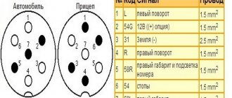
The designation of the legs is as follows:
- Left turn signal (L). Yellow, 1.5 sq. mm.
- Rear fog lights or +12 V (54G). Blue, 1.5 sq. mm.
- Grounding (“minus”) White/gray, 2.5 sq. mm.
- Turn signal right (R). Green, 1.5 sq. mm.
- Lamp for illuminating the license plate and marker on the right (58R). Red, 1.5 sq. mm.
- Brakes - stop light (54). Red, 1.5 sq. mm.
- Left dimension (58L). Black, 1.5 sq. mm.
Simplified diagram.
In the case of the American version of the 7 PIN socket, the placement of the contacts is slightly different. Here the reverse contact connector has been changed, and there is no section on left and right dimensions. In a number of cars from the USA, the dimensions and STOP signals, which run on the same wire, are not separated.
Alternatively, you can assemble a “Russian” circuit. Its peculiarity is that there may be no wire on the PTF, or there will be only one, connected to the 7th pin of the plug. In this case, the 5th contact is not used or is short-circuited by the 7th.
One example of a 7-pin device is the ATE-05 metal socket from the manufacturer Airline. This is the most durable product for a towbar without an elastic boot.
13 PIN
When choosing a 13-pin socket (ISO 11446), the number of connectors is larger, so you need to be more careful when connecting.
Let's look at the main elements:
- Left turn signal (1/L). Yellow, 1.5 sq. mm.
- Rear fog lamp (2). Blue, 1.5 sq. mm.
- Ground connector for terminals one through eight (3/31). White, 2.5 sq. mm.
- Right turn signal (4/R). Green, 1.5 sq. mm.
- Right side marker and license plate light (5/58-R). Brown, 1.5 sq. mm.
- STOP signal lamp (6/54). Red, 1.5 sq. mm.
- Dimensions on the left and license plate illumination (7/58-L). Black, 1.5 sq. mm.
- Reverse lamp (8). Pink, 1.5 sq. mm.
- Constant voltage at 12 V and 35 A (9). Orange, 2.5 sq. mm.
- Voltage 12 V and 35 A (supplied after turning the key in the ignition), (10). Gray, 2.5 sq. mm.
- "Mass" (11). Black and white, 2.5 sq. mm.
- Signal conductor, reserve (12). Light grey, 1.5 sq. mm.
- Ground for the ninth terminal (13). Red-white, 2.5 sq. mm.
Having before your eyes the pinout of the trailer and towbar sockets, you can easily make connections and carry out an electrical inspection (in case of a malfunction).
In Europe, 7-pin (ISO-1724) and 13-pin (ISO-11446) connectors are in demand. As you can see from the pinout above, the 13-pin version gives more options and has better protection against water and dirt.
The connectors work on 12V systems, but there may be exceptions for the 7-pin connector. They often operate on 6 and 24 V. Thus, cars and trailers with 6-pin systems can use a 7-5 pin connector.
Step-by-step connection instructions
It is recommended to connect the towbar socket to the car with your own hands without cutting the standard wires, but using intermediate connecting blocks, as when installing factory adapters.
You need to purchase the necessary materials:
- the connector itself with a protective cover;
- electrical blocks of suitable design;
- cable with colored conductors with a cross-section of at least 1.5 mm2;
- clamps;
- protective corrugation.
Scheme of work:
- Cut a piece of cable to the required length with plenty of room for processing the ends.
- Remove insulation and tin the wire tails.
- Pass the cable inside the corrugated sleeve.
- Solder the contacts in the socket body, referring to the socket diagram of the car's tow bar.
- Secure the wires in the connecting blocks for the rear lights, also checking their order.
- Insulate all connection points and connect the pads to the car's lighting connectors.
- Lay the harness to the installation location on the tow bar, secure it and close the holes in the body with plugs.
It is better to use silicone sealant to insulate cable entries into sockets and connectors.
Connecting a trailer socket to a KamAZ truck
Owners of KAMAZ trucks often ask what type of socket can be used for a trailer.
The main option is a plug device type PS 325-100 for 24 V. The product is designed to transmit electrical signals to side lights, brake lights, turn signals and other elements. They come with 7 and 15 cores.
In this case, 7-core models are conventionally divided into two types - N and S. The first type is very similar to the other models, and the S-type has the appearance of an empty tube.
Pinout:
- Mass (Part 4), white.
- Left size (G.52), black.
- Turn signal on the left (K.75), yellow.
- Brakes (3.57), red.
- Turn signal on the right (P.74), green.
- Right gauge (Kch. 52), brown.
- Not involved. You can connect a reverse gear or a portable lamp. Blue.
As an analogue, you can use a 24 V socket manufactured by BAAZ). Its pinout is the same, only the manufacturer is different.
When choosing the original PS 325, pay attention to the following points:
- When turning the product over, the lid should not open. It is optimal if it is well spring-loaded and opens only with force from the user.
- The pins inside should not dangle.
- In the fake, the holes at the base are very small. You can check this using a special wire crimper.
- Pay attention to the quality of the internal thread and material. It is very difficult to screw a screw into a fake socket. In addition, the product itself is made of aluminum.
Knowing these points allows you to distinguish a fake from an original and avoid wasting money.
Why do you need an electronic matching unit?
Not in all cases it is possible to simply connect the sockets of the towbar and trailer. If the machine has complex electronics, a matching unit will be required.
Its use allows you to avoid errors when testing the operation of lighting equipment and vehicle electrical systems.
In addition, the matching unit is an invariable thing when it is necessary to transmit a signal using a multiplex bus.
The connection diagram is as follows:
- Signals from the car are sent to the matching unit.
- The latter processes the information.
- If there are no conflicts, the signal is transmitted to the trailer of the car or truck.
For correct operation, the unit must be connected to the battery and the wires must be connected correctly (taking into account the pinout).
The connection diagram is shown below.
About installation methods when connecting a tow hitch
The presence of electronics in the vehicle control system allows the use of an electronic coordination unit in the installation of the electrical system for signaling and trailer control. It will monitor and test control signals through a multiplex program.
If the current in the circuits increases, the device will generate an error in signal transmission. Installation and connection to the connector on the tow mechanism is carried out according to a special program with the connection of a matching device in the circuits.
During installation, it is necessary to use a device in the circuits of the machine that will transmit control signals through the matching unit to the towed mechanism, and not through the detachable part in the trailer.
Direct connection diagrams
They go where the brake lights are. When removing reflective covers, take into account the minimum pressing of the cushioning foam, which serves to prevent dust from being sucked into the interior. Although there are connection diagrams on the Internet, performing this procedure yourself is not so easy. Before connecting, it would be good to study the approaches to the wires. A nuance: on the one hand, cutting the wiring is too lazy, on the other, it’s a pity. Therefore, for the lazy method, connectors with three ends are provided: two with plugs that connect standard devices, and one end with bare wires to the towbar socket.
In addition, you will need additional materials:
- Socket with cover.
- Switching blocks. They come with fuse sockets.
- Wire with a cross section of 1.5-2 mm square. Insulated stranded or single-core wires are used.
- Silicone automotive sealant.
- Tourniquet. It is a 3-meter corrugated pipe made of plastic or metal.
- Clamps for fixing the harness.
It is not difficult to purchase one set. The factory version requires complex switching for the following reasons:
- Using a smaller load eliminates melting and short circuits;
- Guaranteed proper operation of lighting fixtures.
In theory, 11 wires are placed in a bundle. Since the right and left sides are synchronous, the switching theoretically fits into the usual 7 wires. But in this situation, there are three lamps per core, and this increases the load. There is another way to divide the current into right and left sides. The number of wires, mounting sleeves, and fuses increases. This circuit complies with safety standards.
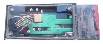
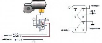
Connecting a VAZ 2110 trailer socket
The VAZ 2110 uses a trailer socket made according to the 12 N, ISO 1724 standard.
There are seven contacts here: two turn signals (first and fourth), fog light (second), ground (third), rear lights and right side lights (fifth), brake light (sixth) and left side lights (seventh).
As in previous cases, wires with a cross-section of 1.5 square meters are used for all contacts. mm, except for the “ground”, which goes to 2.5 square meters. mm.
It is also important to know 5 nuances about connection:
Figure 4. 5 nuances about connecting the towbar socket
Look at the towbar connector in the picture. Switching off will not be particularly difficult, especially if there is a universal component element, which is a towbar connector. It is very convenient to make the connection if the plug and socket match the connectors. Accordingly, a seven-pin socket must be connected to a seven-pin plug. In this option, you can make a normal connection, do not forget to combine the required sockets with the corresponding sockets.
Figure 5. 7 pin Figure 6. Cover
First familiarize yourself with the location of all seven connectors. If they coincide visually, then you can simply try to connect one to the other. If the towbar socket is of high quality, then it must have a cover. It is needed to protect against various external influences. Such protection will be required at a time when the towbar is not connected to the trailer.
Figure 7. Splicing
You can connect electronics in a simpler way. To perform such an operation, it is necessary to combine several leashes into a group and create an effective symbiosis of the supply of electrical signals. You can splice the contacts of two headlights, reverse lights, brake lights, fog lights and side lights. This is explained by the fact that when operating the car they will be used synchronously. Fastening is provided using brackets.
The next method involves changing the car's electrical system. This change consists of combining several wires that lead to the rear light and signal electrics of the trailer. They must be connected to the wires from the coupling device. If the vehicle has a complex electrical circuit, then you will have to spend a little more effort than in previous options. If the car's signal and light bulbs work without a special microprocessor, then you can connect a 7-channel towbar connector. Before you begin the operation, you should make sure that there are enough wires. If necessary, you can make the wiring elements yourself using a three-core copper wire of one and a half millimeters. They should be marked “PVS”.
If the connection is made directly, you must have a diagram of the towbar in front of your eyes, as well as a diagram of the car socket.
Towbar socket
To make the connection correctly, you need to supply turn signals, brake lights, as well as side and fog lights via one wire; you also connect license plate lighting there. You will also need to connect several wires that go to ground, the reversing light, if there is one. A special adapter is also installed on the electronic units. We are talking about a coordination unit between the electrics, the towbar and the towed part of the car. If there is such a connection, all connected parts will work smoothly and will not create problems for the motorist. Connecting the towbar coordination unit is done by yourself.
Photos of towbar connection diagrams will always help in your work if difficulties arise.
Connecting a trailer socket
How to connect a trailer, knowing the pinout of the socket?
There are 2 ways to connect a trailer with lights. The first one is called “regular”. Its feature is the quick connection of the plug to the socket. But this option is only suitable if the tow bar is equipped with a socket box. Another wiring connection option is more universal. It provides for connecting the wiring contacts and signal circuits on the car.
But if an on-board computer is installed on the car, problems with the operation of the lighting devices cannot be ruled out. Unfortunately, not all on-board computers “recognize” a large trailer connected in this way. Therefore, its management can be complicated by the appearance of information about a failure in the system.
Using the trailer socket connection pinout, connecting all the parts is quite simple. To do this, the left-turn contact of the socket is connected to the corresponding block on the plug, then the contact is connected to the fog light with the fog light on the towed equipment. The same applies to all the following contacts.
Although most vehicle models have identical pinouts for trailer models, unexpected difficulties may arise when connecting to a trailer. To avoid them, after connecting all the wires through the towbar connector, you must first check them on a tester. If the device works successfully, you can directly turn on the devices on the trailer itself.
conclusions
Now all that remains is to properly connect the trailer to the car and enjoy the result. If you notice a new type of socket or a complete disappearance of the models shown here from the shelves, please let us know. And don't forget to share the article with your friends!
Sources
- https://PricepInfo.ru/spravka/raspinovka-rozetki-farkopa/
- https://AutoTopik.ru/jelektrika/kak-podkljuchit-rozetku-pricepa.html
- https://www.asutpp.ru/raspinovka-rozetki-farkopa-pricepa.html
- https://pricepclub.ru/remont-i-obsluzhivanie/podklyuchenie-rozetki-pritsepa-legkovogo-avtomobilya
- https://avtoshark.com/article/repairs/electronics-repairs/podklyuchenie-rozetki-farkopa-k-avtomobilyu/
- https://elektro220v.ru/oborudovanie-dlya-avto/shemy-podklyucheniya-pritsepa.html
- https://DriverTip.ru/zhizn/pravilnoe-podkljuchenie-rozetki-pricepa-legkovogo-avtomobilja.html
General facts
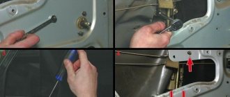
As you know, all electrical wiring in a car is hidden under the trim. The part of the wires that is needed to power the trailer, as a rule, runs from the battery to the dashboard. Then it passes through the entire interior to the rear bumper, and exits at a place called the towbar socket .
As for the trailer, everything is even simpler here.
From the trailer lights, the electrical wiring runs along its bottom and is attached to it using special clamps, usually metal. Next it goes to a connection point called the trailer fork .
Assembling a road train is not a tricky task, but problems are still possible. It is impossible to say exactly where to begin the assembly. Please note that the worst option is switching nodes in the car, which can lead to serious consequences.
Valet service mode: what is it, how easy it is to enable and disable
The most common towbar connection diagram, the so-called standard, is a 7-pin European type. The special feature is the “father” and “mother” nests. They are installed for safe connection in conditions of poor visibility - you will have to try to mix up the connectors.
There is also a 7-pin circuit, but of the American type. The peculiarity is that there is a reverse contact and there is no separation between the right and left rows of lights.
13-pin connectors are used to connect to a passenger trailer. Feature - there are several contacts for negative and positive buses, and there are also additional contacts. They are used to connect a rear view camera.
Expensive modern trailers are equipped with electronic equipment: ABS, ESP, as well as on-board computers. Special connectors are used for pairing. Wiring and connecting can be difficult for an untrained person.
Modern trailers are equipped with additional equipment
How to make garage lighting with your own hands cheaply and quickly
In general, it is better to contact a certified service center. Qualified specialists will carry out the connection taking into account all the nuances.
If you want to take matters into your own hands, do the following:
- Cut 5 wires to the required length, and also label them depending on their purpose;
- Separately measure the wires for the right turn signal lamp and for the license plate light. Their length will be longer;
- Strip the ends of the wires 10 mm. Tin the solder using a blowtorch;
- According to the diagram, secure the ends of the wires in the sockets of the socket. Install the O-ring;
- Roll the wiring into a bundle and also pull it into a corrugated hose;
- According to the diagram, fix the socket on the towbar;
- Lay a corrugated hose with wires inside along a given route in the car;
- Secure the ends of the wires to the connection block;
- Wire the socket according to the diagram. Use insulation at connection points.
At this point the work can be considered completed.
Alternative connection option
There is another way to connect. Here the wires go separately to the connector of the left and right lights. That is, the current load is shared.
The method is considered safe. After all, the load on the soldered wires is reduced. In the first case it was triple, and now only double.
The method resembles the previous scheme. The difference is that the connection is made with 2 wires. This increases the number of sleeves during installation.
This is a universal scheme. Recommended for use in most cases.
Types of connectors
GOST 9200-76 was the main standard in the USSR, which established uniform standards for the electrical connection of trailed equipment to cars and tractors of that time for all industries. It stipulates that all vehicles produced by Soviet industry are equipped with the same seven-pin connectors.
After the appearance on the domestic market of a large number of foreign-made cars and trailers, the complete interchangeability of car sockets was lost. Foreign cars are equipped with trailer hitches (towbars, or towbars) with electrical connections that are often of different types.
Today in operation you can find the following types of compounds:
- seven-pin connector of the “Soviet” type (according to GOST 9200-76);
- 7-pin Euro connector (has a difference in the wiring cross-section and wiring of the 5th and 7th pins);
- seven-pin (7-pin) American type - with flat pins;
- 13-pin with separation of positive and negative buses;
- 15-pin for heavy cargo trailers (has lines for connecting the return indication from the trailer to the driver of the tractor).
Non-standard types of connectors are used in addition to the basic one for connecting other electrical circuits (rear view cameras, on-board circuits of a caravan trailer and the like).
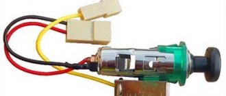
What is a towbar socket
The towbar socket is a connector with electrical contacts that is used to connect the trailer to the vehicle. It is located near the towbar, and the corresponding plug is connected to it. Using a socket, you can safely and correctly connect the electrical circuits of your car and trailer.
Towbar socket
When connecting an outlet, the term “pinout” is used (from the English pin - leg, output). This is the pin layout for proper connection.