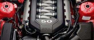
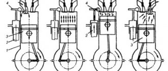
Cars equipped with diesel engines are the most sensitive to the quality of combustible material. The fuel system of a diesel engine occupies one of the central places in the design of the power unit. Operations to repair and restore the functionality of the system are complex and high cost. Structurally, the diesel power system consists of two circuits - low and high pressure. From the first compartment, the prepared diesel fuel enters the next circuit for direct injection into the combustion chamber.
Diesel fuel
Diesel fuel is one of the products of oil refining. It contains various hydrocarbons (paraffins, naphthenes, aromatics, etc.). The number of carbon atoms included in diesel fuel molecules reaches thirty. The main quality of diesel fuel is its ease of ignition when in contact with hot air. The flammability of fuel is characterized by the cetane number. The higher this number, the less resistant the fuel molecules are to oxidation and the more easily it ignites. Diesel fuel has a cetane number of 40 - 50 (most often 45).
An important characteristic of fuel is also its viscosity at different temperatures. To ensure normal engine operation, fuel should not solidify at low temperatures (up to -60 ° C). In addition, it is necessary that the fuel is non-toxic, has anti-corrosion and lubricating properties, and does not create vapor locks in fuel lines at temperatures up to 50 ° C.
Automotive diesel engines use fuel grades A (Arctic), 3 (winter) and L (summer). The most widely used fuels are grades Z (at negative air temperatures) and L (at temperatures above 0 °C).
Requirements for units and components of the power supply system
The following basic requirements apply to all units and components of the power system:
- tightness
- small weight and dimensions
- reliability
- corrosion resistance
- low hydraulic resistance
- simplicity
- low maintenance cost
Fuel lines and fuel supply system units must be located in the engine compartment of the vehicle in such a way that if they malfunction, dripping fuel does not fall on parts that have a temperature that could cause it to ignite.
General structure of the power system
The diagram of the fuel supply system for a powerful diesel engine is shown in the figure. In general, the fuel supply system includes components located outside the engine (on the frame or in the body of the machine) and on the engine. The first include fuel tanks: fuel collection tank 7, pre-start fuel priming pump 10, fuel distribution valve 77, low pressure fuel lines and some other components. The latter primarily include the main fuel priming pump 8, the high-pressure fuel pump (HPF) 5, the injectors 4 and the high-pressure fuel lines.
When the engine is running, fuel is taken from the fuel tanks by the main fuel pump and supplied to the injection pump under a pressure of 0.05...0.1 MPa. On the way from the tanks to the pump, the fuel passes through the fuel distribution valve, the pre-start fuel priming pump and the coarse filter 9. If the vehicle has only one fuel tank or several tanks communicating with each other, then there is no fuel distribution valve. Before entering the injection pump from the pump, the fuel is cleaned of the smallest impurities in a fine filter 3. The injection sections of the injection pump, driven from the engine crankshaft, at certain moments, according to the operating cycle and operating order of the engine, supply fuel under high pressure (up to 50 MPa or more) in the required quantity to the injectors. Through injectors screwed into the cylinder head, fuel is injected into the combustion chambers at the moments when the compression stroke in the cylinders completes.
Rice. Diagram of the fuel supply system for a powerful diesel engine: 1 - fuel tanks; 2 - valve for air release; 3 — fine filter; 4 — nozzles; 5 injection pump; 6 - engine; 7 — tank for collecting fuel; 8 — main fuel pump; 9 — coarse filter; 10 — pre-start fuel priming pump; 11 — fuel distribution valve; fuel pipelines are indicated by a solid line; pipelines for removing air from the system are indicated by dotted lines
Before starting the engine, the system is filled with fuel and supplied to the fuel injection pump using a pre-start fuel priming pump. After starting, this pump does not function.
If air enters the injection pump and the high-pressure pipelines connecting it to the injectors, the fuel supply to the cylinders is disrupted. Consequently, the normal operation of the engine is disrupted. In order to prevent air from entering the fuel injection pump along the fuel path, an air separator is placed next to it, located at the highest point of the system. Typically, the air separator is placed in the cover of the fine filter. Before starting the engine, if necessary, the air accumulated in the air separator is diverted into the air cavities of the fuel tanks 1 through the tap (valve) 2 to release air. To do this, with the engine not running, open the tap (valve) and use the pre-start pump to bleed the system. In this case, the fuel displaces air from the air separator into the air cavity of the fuel tank through the fuel distribution valve (as shown in the figure) or directly.
Diagnostic instructions
The first step is to free access to the ramp and fitting installed at the end of the manifold. Remove elements that interfere with measurements - air duct, filter housing, crankcase ventilation pipe, etc. (the list of parts depends on the car model). Proceed to measuring, following the instructions:
- Unscrew the protective plastic cap from the diagnostic fitting on the ramp.
- Place a cut-off plastic container and use a cap to unscrew the spool valves to release the pressure previously pumped up by the pump. You can press the valve or turn the spool 2-3 turns.
- Place one end of the gasoline hose onto the pressure gauge fitting and secure with a clamp. Unscrew the spool from the manifold, pull the second end of the hose onto the pipe.
- Turn on the ignition, and the electric fuel pump will pump fuel into the system. Make sure there are no leaks at the joints of the diagnostic tool.
- Start the engine and record the fuel pressure in the rail using the pressure gauge.
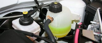
Fuel tank
The fuel leaked into the nozzles between the needle and the nozzle is discharged through drain pipelines into a special tank 7 or into some main fuel tank.
Fuel tanks are used to store fuel. They can have different configurations and capacities depending on the design of a particular vehicle. The total capacity of the fuel tanks is determined by the vehicle's range (usually at least 500 km). Most often, tanks are made of sheet steel or high-strength plastic that is resistant to chemically active fuel. To prevent corrosion, the internal surfaces of steel tanks are coated with bakelite varnish, galvanized or tinned. In order to increase the rigidity of the tanks, sometimes grooves are stamped on their walls, and non-solid partitions are installed inside, which also reduce the free surface area of the fuel and weaken its vibrations during vehicle movement.
Filler necks of fuel tanks are usually equipped with strainers. Settling tanks are placed at the bottom of the tanks. If the tank has a significant capacity, then the fuel is drained through a hole with a plug and a ball valve located above the sump. In this case, a special wrench with a hose is used. The air space of the tanks is connected to the atmosphere through drainage tubes or other special devices, which should exclude the possibility of fire entering the internal cavity of the tank and fuel leaking out during sudden shocks of the vehicle, and also (if possible) ensure purification of the air entering the tanks. Measuring rods were previously used to measure the amount of fuel in tanks. Currently, for this purpose, electrical float-type sensors are most often used, sending an electrical signal proportional to the fuel level to the corresponding indicator on the vehicle dashboard.
WE DIAGNOSE
There is a minimum of equipment without which it is unreasonable to start working. Diagnostics of electronic systems begins with reading fault codes, checking sensors and actuators. There are no special diesel scanners, there are universal ones, that is, for a wide range of cars, or dealer ones - for a specific brand. To study the signal from the device under test, you need an oscilloscope. But it is expensive; it is more profitable to buy a scanner with an additional oscilloscope function.
Fuel pressure is checked with pressure gauges. Low - mechanical, with a scale of up to 10 bar, and high - with a special device with adapters and a range of at least 2000 bar. And to measure the amount of fuel drained from the injectors, you need your own set.
The troubleshooting algorithm depends on the nature of the failure. If the engine does not start (electronic locks and forgotten secrets do not count), we check the integrity of the timing drive. If the starter rotates the crankshaft with force, this is not bad for the owner, but if without resistance, the repairmen will be happy: the work ahead will be expensive. After all, diesel engines are “plug-in” - when the timing drive is destroyed, the pistons bend the valves, and then whatever happens.
Fuel lift pump
The main fuel priming pump ensures uninterrupted supply of fuel from the tanks to the injection pump when the engine is running. It is usually driven by the engine's crankshaft or camshaft. An autonomous electric motor powered by a vehicle generator can also be used. The use of an electric drive ensures uniform fuel supply regardless of the crankshaft speed and the possibility of emergency shutdown of the entire system. There are various designs of fuel priming pumps. They can be:
- gear
- plunger (piston)
- rotary (plate type)
As a rule, plunger and rotary pumps are used.
Plunger fuel priming pump
The plunger fuel priming pump consists of a housing 5, a plunger 7 with a spring 6, a pusher 10 with a roller 77, a spring 9 and a rod 8, as well as valves - inlet 4 and discharge 1 with springs. The pusher and plunger can move up and down. The upward movement occurs when the eccentric 72, manufactured as one piece with the injection pump cam shaft, is turned; downward movement is provided by springs 6 and 9.
When the eccentric protrusion runs off the pusher roller, the plunger moves downward under the action of spring b, displacing the fuel located under it into the pump discharge line. At this time, the discharge valve is closed, and the intake valve is open under the influence of vacuum above the plunger, and fuel flows from the intake line into the cavity above the plunger. When the pusher and plunger move upward, the inlet valve closes under the influence of fuel pressure, and the discharge valve, on the contrary, opens, and fuel from the cavity above the plunger enters the lower chamber under the plunger. Thus, fuel injection occurs only when the plunger moves downwards.
If the fuel supply to the engine cylinders is reduced, the pressure in the exhaust pipe of the pump, and therefore in the cavity under the plunger, increases. In this case, the plunger cannot move down even under the action of spring 6, and the pusher with the rod moves idle. As fuel is consumed, the pressure in the discharge cavity decreases, and the plunger, under the action of spring 6, again begins to move downward, providing fuel supply.
Rice. Diagram of a plunger fuel priming pump: 1 - discharge valve; 2 — manual fuel pump housing; 3 — piston of the manual fuel pump; 4 — inlet valve; 5 — fuel pump housing; 6, 9 — springs; 7 - plunger; 8 — rod; 10 - pusher; 11 — roller; 12 - camshaft eccentric
Rice. Diagram of a rotary fuel priming pump: 1 — pressure reducing valve spring; 2 - pressure reducing valve; 3 - bypass valve; 4 — bypass valve spring; 5 - floating finger; 6 - plate; 7 - rotor; 8 — guide glass; A—B—pump chambers
The plunger fuel priming pump is usually combined with pump 2 for manual fuel priming. This pump is installed at the inlet of the main fuel pump and is activated manually by moving the piston 3 with the rod. When the piston moves upward, a vacuum is formed under it, the inlet valve opens, and fuel fills the space under the plunger. As the piston moves downward, the intake valve closes and the discharge valve opens, allowing fuel to pass further along the fuel line.
Rotary fuel priming pump
, rotary-type fuel priming pumps are mainly used . The pump rotor 7 is driven into rotation by the engine crankshaft. The rotor has slots into which plates 6 are inserted. One (outer) end of the plate slides along the inner surface of the guide cup 8, and the other (inner) - along the circumference of the floating pin 5, located eccentrically relative to the rotor axis. At the same time, they either move out of the rotor or move into it. The rotor and plates divide the internal cavity of the guide cup into chambers A, B and C, the volumes of which continuously change as the rotor rotates. The volume of chamber A increases, so a vacuum is created in it, under the influence of which fuel is sucked from the inlet line. The volume of chamber B decreases, the pressure in it increases, and fuel is forced into the discharge cavity of the pump. The fuel located in chamber B passes from the inlet of the glass to the outlet. When the pressure in the discharge cavity increases to a certain level, the pressure reducing valve 2 opens, overcoming the force of the spring 7, and excess fuel is released back into the inlet cavity of the pump. Therefore, constant pressure is maintained in the discharge cavity and outlet pipeline. Before starting, when the engine and, therefore, the main fuel priming pump are not running, fuel can be pumped through it by a pre-start fuel priming pump. In this case, the bypass valve 3 opens, overcoming the force of the spring 4. In the closed position, the disc of this valve covers the holes in the pressure reducing valve disc.
Measuring process
Fuel pressure must be measured in 4 operating modes, that is, 4 different measurements will be required.
With the ignition on
When the ignition is turned on, the fuel pump must supply the system with the fuel needed to start the engine. Therefore, we simply turn on the ignition and look at the readings. The pressure must be above 3 atmospheres.
Idling
Just start the engine and look at the pressure gauge readings. Normal pressure is 2.5-2.7 atmospheres.
When the return line is turned off
Almost all modern cars have a fuel pressure regulator. It is aimed at preventing excessive pressure from being created in the system. When the limits are reached, it resets the pressure to normal. We clamp the return pipe and get the result on the pressure gauge.
It should be about 7 atmospheres. If you have a 6 atmosphere pressure gauge, the needle should be “filled up”.
Under loads
And one more stage of measurement is the measurement of pressure drops under loads. Just apply the throttle (you can just “tug” the throttle cable if you have a mechanical one) and observe the changes.
During recharging, the pressure should be about 3 atmospheres, and then drop to the idle value - that is, up to 2.5 atmospheres.
Pre-fuel priming pump
Before starting the engine, the system is filled with fuel and supplied to the injection pump using a pre-start fuel priming pump 70. Previously, manually driven plunger and diaphragm (diaphragm) type pumps were widely used. However, nowadays, centrifugal vane pumps driven by an electric motor powered by electrical energy from a battery are increasingly being used. They provide faster fuel pumping, do not require the driver’s muscular energy, and can be used as emergency ones in case of failure of the main fuel priming pump.
Coarse and fine fuel filters
Fuel is purified from mechanical impurities and water in coarse 9 and fine 3 filters. The coarse filter, installed in front of the main fuel pump 8, traps particles measuring 20...50 microns, which account for 80...90% of the mass of all impurities. A fine filter, placed between the main fuel pump and the injection pump, traps impurities with sizes of 2...20 microns.
Currently, the following types of coarse filters are used in diesel power plants:
- mesh
- tape-slit
- plate-slit
For mesh filters, the filter element is a metal mesh. It can be used to form concentric cylinders through the walls of which fuel is pressed, or disk-shaped sections strung on a central pipe with holes in the wall connected to the outlet pipeline.
In a slotted belt filter, the filter element is a corrugated glass with a profile tape wound on it. Through the gaps between the turns of the tape formed by its protrusions, fuel from the space surrounding the filter element enters the depressions between the corrugated glass and the tape, and then into the cavity between the bottom and the lid of the glass, from where it is removed through the outlet pipeline.
The filter element of a plate-slit filter is a hollow cylinder made up of identical thin annular disks with folded projections. Due to these protrusions, gaps are formed between the disks. The fuel flows to the outer and inner surfaces of the cylinder and, passing through the slots between the disks, is cleaned. The cleaned fuel is directed through the end holes in the disks to the upper part of the filter to the outlet.
Very often, a coarse filter is combined with a settling tank for water contained in diesel fuel. In this case, it is necessary to periodically unscrew the sump plug to remove accumulated water from it.
In fine filters, cardboard elements of the “multi-beam star” type or bags of cardboard and felt disks are usually used as filter elements. Less commonly used are frames with padding that absorbs mechanical impurities (for example, mineral wool), frames with fabric or thread winding, etc.
During vehicle operation, fuel filters become dirty, which leads to an increase in their resistance. To ensure that the fuel supply to the injection pump does not stop, it is necessary to periodically wash the coarse filter and replace the fine filter element with a new one.
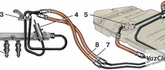
Injection pump. Design and principle of operation
The high-pressure fuel pump 5 is designed for precise dosing of fuel and its supply to the injectors 4 under the required pressure and at a certain moment. In in-line engines, such a pump is placed on the side of the engine, on the upper half of its crankcase. For V-shaped engines it is installed in the cylinder camber. There are many types of injection pumps. In particular, on relatively low-power diesel engines intended for passenger cars, as a rule, a distribution-type fuel injection pump with one injection plunger-distributor is installed. However, powerful multi-cylinder diesel engines are most often equipped with multi-plunger pumps. An example of such a fuel injection pump for a six-cylinder V-shaped diesel engine is shown in the figure.
The pump consists of a housing 5 with covers, six pump sections, a drive mechanism for the pump sections and a mechanism for rotating the plungers. Each pump section includes a plunger 8, a return spring 11 with support washers, a discharge valve 3 with a seat, a spring and a stop, as well as a fitting 2 and other auxiliary guides and fasteners. The drive mechanism of the pump sections consists of a cam shaft 7 and roller tappets 6 with adjusting bolts. The mechanism for turning the plungers includes rotary bushings 10 with toothed rims and a gear rack 9 with bushings and a limit screw. Along the sections in the pump body, two longitudinal channels 1 and 4 are drilled, connected to each other by transverse channels. Each plunger is very precisely fitted to its sleeve, which ensures that high pressure is achieved with minimal fuel leakage through the gaps.
Rice. High pressure fuel pump: 1, 4 - longitudinal channels; 2 - fitting; 3 - discharge valve; 5 - pump housing; 6 — roller pusher; 7 - cam shaft; 8 - plunger; 9 — gear rack; 10 — rotary sleeve; 11 - return spring
The pump works as follows . The cam shaft is driven into rotation from the engine crankshaft using a gear transmission (the angular speed of the cam shaft is 2 times less than the speed of the crankshaft). Rotating, the cam shaft moves roller tappets 6 with its cams, which lift the plungers up.
The return stroke of the pushers and plungers is ensured by return springs. Channel 4 is supplied with fuel from the fuel priming pump, pre-cleaned in a fine filter.
When the plunger is in the lower position, fuel from channel 4 enters the resulting cavity above the plunger. As the plunger moves upward, the inlet closes and high pressure fuel flows through the injection valve, fitting and high pressure fuel line to the injector.
Fuel injection occurs until the above-plunger cavity is connected to drain channel 1 using axial, radial and helical grooves in the plunger. With a constant stroke of the plunger, determined by the height of the cam protrusion, the amount of fuel supplied to the injector is regulated by turning the plunger using a rack and a rotary sleeve with a toothed rim. The screw groove in the plunger is made in such a way that as it turns, the distance from the edge of the bypass hole associated with channel 7 to the edge of the cut-off edge of the screw groove changes. In this case, the length of the working stroke of the plunger, during which fuel is injected, also changes.
In order for the fuel supplied to the cylinders to burn in a timely manner and the engine to develop the greatest power, it is necessary to slightly increase the fuel injection advance angle as the crankshaft speed increases.
Regulation of this angle for mechanically controlled pumps is ensured by a special centrifugal clutch, which is installed in the injection pump housing and, in proportion to the crankshaft rotation speed, shifts the pump cam shaft by a certain angle in the direction of its rotation.
WE REPAIR
Restoring the pump's functionality can only be done by a specialized workshop with qualified personnel and diagnostic equipment. The cost of repairs is from 7 thousand rubles, then it depends on the complexity. In case of some damage, it is wiser to buy a new injection pump. The usual price, about 30 thousand rubles, will shock the tight-fisted diesel operator, which is why repaired or restored products are in use.
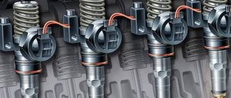
A CR diesel with high mileage is often impossible to start due to a malfunction of at least one of the injectors. Fuel leakage through its valve does not allow the pressure in the rail to rise to starting values. There is a special diagnostic kit to check the pressure at start-up. It includes a control pressure gauge, a pressure sensor, connection tubes, plugs instead of actuators and backflow measuring containers.
Nozzle
The injector serves to supply fuel into the engine cylinder under high pressure in a finely atomized form.
A typical injector includes a body 5 with a spray nozzle 3, a guide pin 4 and a union nut 2, a spray needle 1 with a rod b, a spring 7 with a support washer, an adjusting screw 9 and a bushing 8, a cap nut 10 and a fuel inlet fitting 12 with a strainer 11 The sprayer and the needle must be very precisely adjusted to each other. In the upper part of the atomizer there is one annular and several (most often three) vertical fuel channels, and in the lower part there are central inlet and outlet channels with spray holes. The diameter of these holes is 0.2...0.4 mm. The needle closes the exit channel with its lower conical end. The sprayer is tightly attached to the nozzle body using a union nut. The fuel channel of the housing is connected to the annular channel of the atomizer through its vertical channels. The correct position of the sprayer relative to the body is ensured by a guide pin.
Rice. Nozzle: 1 — spray needle; 2 - union nut; 3 - sprayer; 4 - guide pin; 5 — nozzle body; 6 — rod; 7 - spring; 8 — bushing; 9 — adjusting screw; 10 - cap nut; 11 - mesh filter; 12 — fuel inlet fitting
Fuel supplied to the nozzle through the fuel inlet fitting passes through a strainer and enters its annular cavity through the fuel channels of the housing in the upper part of the nozzle. Upon reaching the required pressure in this cavity, which acts, among other things, on the conical belt of the needle, it rises upward, overcoming the resistance of the spring. At this time, the outlet channel opens, and fuel flows through it and the spray holes into the combustion chamber of the engine cylinder.
After the pumping section of the injection pump stops supplying fuel and the pressure drops, the needle sits back in its seat, stopping fuel injection. The fuel that has leaked through the leaks enters the upper part of the nozzle and through the holes in screw 9 and nut 10 through a special pipeline is drained into tank 7 to collect fuel.
Important to remember
When you check the fuel pressure with the ignition on, note that after the ignition is turned off, the pressure in the rail drops to 0.7-1 atmosphere and remains at this level. If it drops to 0, the problem is in the fuel pressure regulator.
Try increasing the number of revolutions to 3000 - if the pressure gauge needle does not stay constant, but falls, this may mean that it is time to change the fuel pump.
If the pressure builds up for a very long time or is lower than required, the fuel filter, fuel pump filter or fuel line may be clogged.
I hope you found it interesting and will take note of this. Subscribe to the channel and give it a thumbs up to see even more interesting articles on automotive topics in your feed every day.
Source
Battery fuel supply system
Modern stringent requirements for the level of emissions of harmful substances from internal combustion engines have forced diesel designers to look for new solutions in the field of fuel equipment for them. The fact is that even the most advanced fuel injection pumps cannot provide such a fuel pressure at which it would be sprayed so finely that it could completely burn out in the combustion chamber.
Incomplete combustion leads to higher fuel consumption, and most importantly, to an increase in the concentration of harmful substances, in particular soot, in the exhaust gases. In this regard, the so-called battery fuel supply system is now increasingly being used for diesel engines with direct injection.
The main difference between such a system and the “classic” one is the presence of a common fuel rail (pressure accumulator), in which very high pressure is created during engine operation.
The fuel rail is connected by high-pressure pipelines to electronically controlled fuel injectors, the needles of which are moved using electromagnets according to signals from the engine control computer (electronic unit). This fuel supply system allows you to optimize engine performance in almost all respects.
Tuning
Chip tuning of diesel engines can be performed both by reprogramming the control unit and by changing the turbine pressure.
It should be said that chip tuning of a diesel engine is simple and affordable. At the same time, it allows you to significantly increase the power of the motor without reducing its service life.
Note that for high-quality operation of such a chipped power unit, it is necessary to remove the catalysts or install their decoys. It should be remembered that chip tuning of a diesel engine should be performed exclusively by an experienced specialist who knows what compression should be in the engine.
Currently, there are various programs to increase the power of the power unit by reprogramming its control unit. In this case, there is the possibility of both easy tuning and a dramatic increase in power.