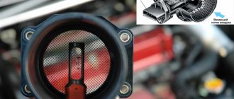
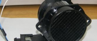
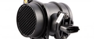
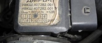
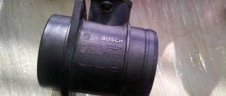
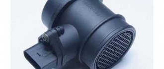
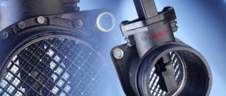
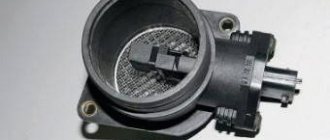
The main link in preparing the fuel mixture of an engine operating on the MAF system (Mass Air Flow stands for Mass Air Flow) is the mass air flow sensor, or MAF for short. Determining the amount of air entering the engine cylinders is one of its main functional responsibilities. The mass air flow sensor in modern fuel-injected cars is used structurally in conjunction with an air temperature and atmospheric pressure sensor, which indicate to the control unit in which climatic environment the engine is currently operating. Made in the form of a plastic pipe with a diameter of 70 mm into which the measuring element is mounted. Some sensors are directly attached to the air filter housing, for which it is equipped with a flange for mounting with two bolts.
Symptoms of Poor Mass Air Flow
Symptoms of a faulty mass air flow (MAF) sensor may include:
- poor fuel economy
- erratic performance
- hesitation when accelerating
- hard start
- no engine start
- stalls when in gear
- low engine power
- the engine is running in an unknown mode
How to extend the life of MAF
The reliability and durability of the air flow sensor depends entirely on the condition of the air itself.
That is, you need to monitor and regularly change the air filter, preventing it from becoming completely clogged, getting wet in the rain, as well as installation with errors, when gaps remain between the housing and the filter element.
It is also unacceptable to operate the engine with malfunctions that allow back emissions into the intake channel. This also destroys the MAF.
Otherwise, the sensor is quite reliable and does not pose any problems, although periodically monitoring it with a scanner will be a good measure to maintain normal fuel consumption.
Source
What does the MAF or DMR sensor do?
MAF is a mass air flow sensor (abbreviated as MAF), it measures the volume and density of air entering the engine . Some also measure the temperature of the air entering the engine. The computer uses this measurement along with other inputs to calculate the best air-fuel ratio and timing the ignition to suit engine operating conditions. On a vehicle with an automatic transmission, the MAF sensor can also help determine shift timing.
Types and features of the mass air flow sensor
There are many ways to measure mass air flow; three of them are used in cars with varying degrees of popularity.
Volume
The simplest flow meters were built on the principle of installing a measuring blade in the cross section of passing air, on which the flow applied pressure. Under its action, the blade rotated around its axis, where an electric potentiometer was installed.
All that remained was to remove the signal from it and submit it to the ECM for digitization and use in calculations. The device is as simple as it is inconvenient to develop, since it is quite difficult to obtain an acceptable characteristic of the dependence of the signal on the mass flow. In addition, reliability is low due to the presence of mechanically moving parts.
A flowmeter based on the Karman vortex principle is a little more difficult to understand. The effect of the occurrence of cyclic turbulences of air as it passes through an aerodynamically imperfect obstacle is used.
The frequency of these manifestations of turbulence depends almost linearly on the flow speed, if the size and shape of the obstacle is correctly selected for the desired range. And the signal is issued by an air pressure sensor installed in the turbulence zone.
Currently, volumetric sensors are almost never used, having given way to hot-wire devices.
Wire
The operation of such a device is based on the principle of cooling a platinum spiral heated by a fixed current when placed in an air flow.
If this current is known, and it is set by the device itself with high accuracy and stability, then the voltage on the spiral will depend with ideal linearity on its resistance, which, in turn, is determined by the temperature of the heated conductive thread.
But it is cooled by the oncoming flow, so we can say that the signal in the form of voltage is proportional to the mass of air passing per unit time, that is, exactly the parameter that needs to be measured.
Of course, the main error will be made by the temperature of the air at the inlet, on which its density and heat transfer ability depend. Therefore, a temperature-compensating resistor is introduced into the circuit, which, in one way or another of many known in electronics, takes into account the correction for the flow temperature.
Wire mass air flow sensors have high accuracy and acceptable reliability, therefore they are widely used in manufactured vehicles. Although in terms of cost and complexity this sensor is second only to the ECM controller itself.
Film
The differences between a film MAF and a wire MAF are purely in the design; theoretically, it is still the same hot-wire anemometer. Only heating elements and temperature-compensating resistances are made in the form of films on a semiconductor crystal.
The result is an integrated sensor, compact and more reliable, although more complex from the point of view of production technology. It is this complexity that does not allow for the same high accuracy that platinum wire provides.
But excessive precision is not required for the mass air flow sensor; the system still works with feedback on the oxygen content in the exhaust gases, and the necessary correction of the cyclic fuel supply will be made.
But in mass production, a film sensor will cost less, and due to its construction principle it is more reliable. Therefore, they are gradually replacing wire sensors, although in fact both are inferior to absolute pressure sensors, which can be used instead of mass air flow sensors by changing the calculation method.
Types of mass air flow sensors
Although there are two common types of MAF, hot wire and hot film, the most common types are hot wire. Test procedures for troubleshooting hot wire sensors may vary depending on the make of vehicle. You can further categorize MAF sensors into low frequency, voltage and high frequency types.
Some car models use a MAF that sends a voltage signal to the computer. But later models may use a voltage frequency signal.
What you need to troubleshoot your MAF sensor
No matter what type of meter you have, you need to know how to test the MAF, the general troubleshooting steps remain basically the same. If you have a decent digital multimeter (DMM), you should be able to test your MAF sensor on most vehicles. However, in some cases you will need a digital multimeter with a frequency scale.
In any case, it is advisable to have a vehicle repair manual for your specific model to check the correct specifications and type of meter that is used in your vehicle. If you don't have this manual, you can look for one at auto stores or online.
Below are general testing procedures that can be applied to most car models on the road today.
Let's imagine a fairly common situation: hot July 2013.
A family of four, father, mother and two children, head out to the lake on a Friday evening with a tent. On Saturday evening, when the heat subsided, the family decided to clean up the car. While mom and the children were polishing the car inside and out, dad decided to do a little maintenance for the car beloved by the whole family. No sooner said than done! The cabin filter, which had not been changed for a year, was replaced. The throttle valve has been removed and cleaned. Spark plugs replaced. The already very tired air filter was also replaced. Sunday evening is approaching. It's time to get ready to go home. The tent, kettles and other belongings take their place in the trunk, the crew takes their place in the cabin. Key to start! The engine happily comes to life. Dad turns the gear selector to position “D”, releases the brake and... the car engine stalls... The display shows a “check” and a triangle with an exclamation mark...
But you can’t take us with your bare hands! Dad knows very well that he couldn’t mess up. He has been servicing the Prius on his own for 3 years, as they say, “he ate the dog.” The keys are taken out of the trunk and a circular check begins: damper, spark plugs, filter, connectors. Everything is assembled correctly, but the car does not want to go home... The sun is setting, there is nothing to do and there is only one way out - a tow truck.
On Monday morning, the car on the back of a “tow truck” arrives at our service center. The client vividly tells how he tried to defeat this “stupid iron monster” on his own. The scanner is not connected yet, the work order is being filled out. While I’m filling out the form, I’m trying to conduct a direct conversational acceptance: I ask questions about the last refueling, the marking of the installed spark plugs, the presence of mosquitoes when performing work on the lake...
The last question threw my dad into a stupor; he didn’t understand: “What mosquitoes!?” - Yes, the most ordinary ones that bite painfully. - Yes, there were just clouds of them there!!!
All! You don’t have to connect the scanner; the diagnosis has been made. In front of the amazed owner, we unfasten the connector of the mass air flow sensor, unscrew the two screws and pull out the sensor. Exactly! One little bloodsucker committed suicide on the hot threads of the air flow sensor! We blow away the charred corpse of the mosquito, put the sensor in place and... oh, a miracle! Before the eyes of the amazed owner, his dead iron horse comes to life!
As they say: “but it wasn’t the reel...”. Let's now take a closer look at how a small mosquito could kill such a large iron monster as a Prius!
What does this mass air flow sensor consist of, who invented it, how does it work and how to maintain it?
First, let's see where it stands and how convenient it is to get to it (shown by the arrow):
As you can see, the location is very convenient. And up close the sensor looks like this:
Wire color:
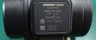
And markings:
Some italics: I was a little hasty with these photos because I initially wanted to show “how it is recommended to maintain the car” - picture below. This is, generally speaking, how it should be done. And if you don’t see this, ask the car service workers so that, before doing any work on your car, they attach capes to the wings (number “2” in the figure, there are special magnets inside; a trifle, as they say, not only “pleasant”, but also protects from scratches, etc.):
And if you do something on the car yourself, throw something soft on the fenders - it won’t take much time, and the guarantee against scratches, chips and scuffs will be reliable.
But let's return to our mass air flow sensor. Let's unscrew, remove the MAF sensor and take a closer look at it:
The schematic design of the mass air flow sensor looks like this:
On the left in the figure is a schematic electrical diagram, and on the right is the appearance and location of the temperature sensor and measuring element. The black arrow shows the direction of air flow. To see these sensors, which are thin wires, you need to turn the sensor over and look inside:
And since there is an opportunity, let’s cut off the top part:
Well, both the temperature sensor and the measuring element are clearly visible. And from above, from the side of the air filter, everything together from above will look like this:
For the most curious, here is a photo of what is under the sensor cover:
This is clear, you get an idea of where the MAF sensor is located and what it consists of. Next, you need to understand “how and on what principles the MAF sensor works.”
MAF-sensor, Mass Air Flow, or mass air flow sensor.
Necessary for precise dosage of the mixture supplied to the cylinders.
Based on the signal from the MAF sensor, the engine control controller maintains a stoichiometric mixture ratio of 14.7:1. In other words, the mixture is considered normal (neither lean nor rich) if 14.7 parts of air and 1 part of fuel from the total composition of the mixture are supplied to the cylinder. The air flow meter does not measure either the amount of oxygen or the amount of other chemicals. elements in the air. The MAF sensor works on the principle of flow-cooling of the internal element - a thread through which an electric current passes. The pistons, drawing air into the cylinders, create an air flow inside the intake tract, where the MAF is located, which cools the thread inside the sensor, changing its resistance.
A working mass air flow sensor has the following characteristics: The voltage of the mass air flow sensor ADC with the engine not running should be 0.996 Volts. Values of 1.016 and 1.021 are still acceptable; if more than 1.035, the sensitive element of the sensor is clogged and most likely the sensor is already lying. The degree of deviation of the mass air flow sensor readings from the norm can be assessed with the engine running at different speeds. For a 1.5-liter engine at idle the readings should be 9.5-10 kg/hour, at 2000 rpm - 19-21 kg/hour. If at 2000 rpm the mass air flow sensor shows about 18-17 kg, the car is more or less pulling, the consumption is even lower than normal - you can drive and save gasoline if you are not in a hurry. If it shows 22-23-24 kg/hour, the car pulls well, but the consumption is 10-11 liters per hundred, and in the cold it may not start well due to fuel overflow.
The sensor that determines the temperature of the intake air is an element of the ECM - the electronic engine management system. The device is located between the air filter housing and the air duct inlet, in the mass air flow sensor housing or in the lower part of the air filter housing.
An air temperature sensor (hereinafter referred to as DTS) is a thermistor - a semiconductor resistor that has a pronounced relationship between the ambient temperature and electrical resistance.
A thermistor's "negative temperature coefficient" means that as the temperature increases, the electrical resistance becomes less. High temperature causes low resistance - 70 ohms at 130°C, and low temperature, on the contrary, gives high resistance - 100.7 kOhm at -40°C.
From the electronic control unit (ECU), a voltage of 5 volts is supplied to the air temperature sensor through a constant resistance resistor, which is located in the ECU unit. The temperature of the incoming air is calculated by the ECU based on the voltage drop across the DTV with variable resistance. The air temperature value is a parameter that affects almost all systems controlled by an ECU with older flow meters. However, if a modern mass air flow sensor is installed in the system, incorrect readings or a complete malfunction of the air temperature sensor do not particularly affect the operation of the engine, only slightly “dulling” the vehicle’s acceleration characteristics, which are simply IMPOSSIBLE to notice “by eye” without a scanner!
But this will affect fuel consumption. So if you have increased fuel consumption, be sure to check the serviceability of the sensor!
If the electrical circuits of the sensor are faulty, after some time the ECU will store an error code and activate a control signal on the driver’s control panel “CHECK ENGINE” as a visual warning of a malfunction in the system. The unit will independently calculate the air temperature using the signal from the coolant temperature sensor, or set the default value, approximately 33°C. And the car will continue to drive as if nothing had happened on an overly enriched mixture!
And now the most important thing: “How to check?”
I am sure that this question worries all Prius car owners. Let's start with the errors that the control unit records and shows them on the scanner, here they are: Checking the air flow sensor
1. By voltage change From left to right: brown, white, green, red, black.
We take power from the battery and apply: • +12 volts to black • -12 volts to red Connect the voltage to green • “minus” to red
Next, we supply air flow to the flow meter and observe the voltage change on the voltmeter. If the voltage does not change, the flow meter is faulty (see photo below).
2.
Checking the air flow sensor by resistance
We measure the resistance between the brown and white wires.
It should be: At an ambient temperature of minus 20 degrees Celsius 13.6-18.4 Kom
At an ambient temperature of plus 20 degrees Celsius: 2.21-2.69 Kom At an ambient temperature of plus 60 degrees Celsius: 0.49-0.67 Kom If the parameters go beyond the specified limits, the functionality of the sensor is not guaranteed.
If you don’t check it yourself, but go to a car service center, you can show the specialist (if he doesn’t have one) a table from the manual, from which he can understand what to check, how to check and what to focus on:
And after he checks, show him one more recommendation from the repair manual: • If the result is not as specified, replace the mass air flow meter. • If the result is within the specified range, remove and inspect the mass air flow meter
As you can see, checking the MAF sensor is not particularly difficult. And by performing such checks, you will be able to independently understand whether your sensor is working or not. And save on a trip to a car service center.
And returning to the beginning of our story: “how a small mosquito could kill such a large iron monster as a Prius” is a question mark.
Surely, many, having looked at photos and drawings, understood this: a mosquito, whose weight is only a few grams, simply fell and stuck to one of the measuring wires, with the help of which the engine control unit determines the mass of air entering the engine and thereby determines the required amount of fuel, which must be fed into the cylinders. The measurements were distorted - the control unit began to think and began to output to the injectors “a certain average time” for opening the injectors, which led to a malfunction.
But this is, let’s say, a “critical” malfunction. In practice, in most cases it happens differently:
Customers come complaining about high fuel consumption. We carry out diagnostics and see that the control unit did not record the above errors based on the flow sensor. Everything seemed fine. And many “diagnosticians” calm down on this, dismissing the mass air flow sensor as the cause of increased fuel consumption.
In fact, we must analyze the readings of the flow sensor with the existing fuel trim of the engine. How to do this is the topic of a separate article, which I plan to do in the near future.
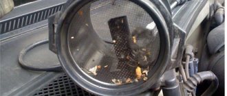
But without any analysis of the readings, we can see the following picture on the sensor:
Those. engine air filter clogged with dirt and fluff.
What do you think is the state of our mass air flow sensor? And we can also determine its condition with the help of our pair of eyes. To do this, just look at the temperature sensor of the MAF sensor. After all, it also performs another function for us - an indicator of contamination of the flowmeter measuring element.
How it works in practice. Let's look at this photo:
We see that the “droplet” of the temperature sensor is covered with a large layer of soot and dirt, and looks like a “dirty match head”. Accordingly, the measuring element of the flow meter is covered with the same “blanket” of dirt. And the flow meter from under this “dirty blanket” simply cannot correctly read how much air has entered the engine.
On a clean sensor, the droplet and meter spirals should look like this:
Those. in the drop we should see, as the Japanese express it, the American “$”. In other words, inside the amber droplet we should clearly see the thermistor head, which in shape resembles the generally accepted designation of American currency.
How to bring a “dirty” sensor into a “clean” state? The easiest way is non-contact washing of this sensor and the measuring element of the flow meter using special automotive chemicals. Any “carburetor cleaner” or something similar that contains a strong solvent is good for this. Under no circumstances should you direct a strong stream of cleaner spray onto the flow meter thread. By doing this you deform it, i.e. you will disable it with your own hands. You can wash only with a “reflected” jet or by lightly pressing the cylinder valve. I would also like to draw your attention to the fact that this solvent, after use, should not leave behind any “film”. We use Japanese and American-made cleaners.
The last point that I would like to draw the attention of readers is the rubber sealing ring of the mass flow sensor. You can see what it looks like and its original number in the photo
So this ring, due to the fact that it is made of simple rubber, is very sensitive to many types of “cleaners” and “solvents”. Therefore, before cleaning the mass air flow sensor using chemicals, it is better to remove it from the sensor.
Gordeev Sergey Nikolaevich
(forum nickname - FERMER) Sverdlovsk region, Beloyarsky district, Kochnevskoye village, Sadovaya st., 33. +7 https://hybridservis.ru
MAF sensor location
Locate the MAF between the air filter box and the throttle body. On some models, the sensor is located inside the air filter housing.
If you need help finding a meter, get a vehicle repair manual for your specific make and model of car.
| Index |
| 1. Quick MAF Diagnostic Procedure Without DMM |
| 2. How to check |
| Power check |
| Voltage Signal Testing |
| Frequency Signal Testing |
| Hot Wire Testing |
| 3. I replaced the faulty MAF sensor, but I see no improvement |
| 4. What if my sensor is faulty? |
Locate the MAF sensor in the air filter assembly.
Restoring and increasing the service life of Nissan mass air flow sensor
This device is one of the most expensive among all sensors in a Nissan car. Its careful operation, as well as timely cleaning measures, will help extend the life of the device and avoid large financial costs.
- Periodically wash the conductive thread and the entire cavity of the device with special sprays and products. At the same time, it is strictly forbidden to enter there with any foreign objects: ear cleaners, matches, cotton pads, etc. To avoid chemical dissolution of various connections and contacts, as well as rubber parts, it is not recommended to wash with ketone- and acetone-containing liquids. Any carburetor cleaning fluid will work here. You shouldn’t even blow through the “inside” of the sensor - you can damage both the thread itself and its contacts.
- Change air filters in a timely manner, which adsorb the lion's share of contaminants that penetrate with the air flow.
- Monitor the wear of the piston rings. Through the cracks in the rubber base of the rings, oil particles fall onto the platinum sensitive element of the sensor, forming carbon deposits, leading to complete breakdown of the device.
If a final and complete failure of the mass air flow sensor on a Nissan has been diagnosed, it must be replaced; such a device cannot be repaired.
Quick MAF Sensor Diagnosis Procedure Without a DMM
Sometimes it is possible to perform a quick diagnosis of the MAF meter without using any test equipment, depending on the specific sensor problem. For example, you can try this when you are dealing with intermittent performance issues, no startup, or poor idle problems.
We recommend reading: When braking, it pulls to the right to the left and pulls to the side
If your car has been experiencing intermittent malfunctions or idle problems:
- Apply the parking brake.
- Set the transmission to park (automatic) or neutral (manual).
- Start the engine and let it idle.
- Open the hood.
- Lightly tap the MAF with the handle of a screwdriver.
- If the engine stalls, idles rough, or idles better, the MAF is likely faulty.
If the engine does not start or runs poorly:
- Open the hood.
- Disconnect the MAF electrical connector.
- Apply the parking brake.
- Set the transmission to park (automatic) or neutral (manual).
- Try running Enigne.
- If the engine starts or idle improves, replace the MAF sensor.
On some vehicle models, you will need to use a digital multimeter that can read frequencies.
Diagnostics of mass air flow sensor
Difficulties in self-diagnosis of a flow meter are caused by the fact that it is a capricious device. Taking readings at the number of revolutions specified in the manual often does not give results. The readings are normal, but the sensor is faulty. Here are several ways to diagnose the performance of the sensor:
- The easiest way is to replace the mass air flow sensor with a similar one and evaluate the result.
- Check without replacement. Disconnect the flow meter. Unplug the sensor connector and start the engine. When the DMVR is disabled, the controller operates in emergency mode. The amount of fuel for the mixture is determined only by the throttle position. At the same time, the engine keeps speed above 1500 rpm. If the car becomes “faster” during a test drive, then most likely the sensor is faulty
- Visual inspection of the mass air flow sensor. Remove the corrugated air intake tube. First, carefully inspect the corrugation. The sensor may be working properly, but the reason for its unstable operation is cracks in the corrugated hose. If the surface is intact, continue the inspection. The elements (platinum threads) and the inner surface of the corrugation must be dry, without traces of oil and dirt. The most likely cause of the malfunction is contamination of the flow meter elements
. - Checking the mass air flow sensor with a multimeter. The method is applicable for Bosh mass air flow sensor with catalog numbers 0 280 218 004, 0 280 218 037, 0 280 218 116. We switch the tester to measure DC voltage, with a measurement limit of 2 Volts.
DMRV contact diagram:
MAF contact diagram
Location from closest to the windshield in order: 1. sensor signal input 2. MAF supply voltage output 3. grounding (ground). 4. output to the main relay. The color of the wires may vary, but the pin locations are always the same. Turn on the ignition without starting the engine. We connect the red probe of the multimeter through the rubber seals of the connector to the first contact (usually the yellow wire), and the black probe to the third to ground (usually the green wire). We look at the multimeter readings. A new sensor typically reads between 0.996 and 1.01 Volts. Over time, tension usually increases. A higher value corresponds to more wear on the sensor. 1.01…1.02 – sensor is working. 1.02…1.03 – the condition is not the best, but working 1.03…1.04 – the resource is at its limit. 1.04...1.05 - agony 1.05...and more - definitely, it's time to change.
All of the home diagnostic methods described above do not provide a 100% guarantee of the reliability of the result. A reliable diagnosis can only be made using special equipment.
How to check the mass air flow sensor
Generally, there are three types of MAFs that have been used for many years: low frequency, DC voltage and high frequency type.
For example, GM used a low frequency type MAF meter in 1988 and older models. He then switched to high frequency sensors starting in 1989. Most new vehicle models also use high frequency sensors.
While doing these tests, try to check for a voltage signal, if you know your MAF sensor is a high frequency type (newer car model), you can use a voltmeter that can measure frequency. If you have an older model car with a low frequency type MAF, you can use a digital multimeter that can measure the car's speed (tachometer, rpm). If necessary, consult your vehicle's repair manual.
If possible, start the engine and let it idle for about 15 minutes to warm up. Then turn off the engine and continue with the following tests.
How to check the DMRV with a tester
Checking the MAF sensor power supply:
- Open the hood.
- Disconnect the MAF electrical connector.
- Set your digital multimeter to 20 volts DC or auto range.
- Connect the red meter wire to the B+ connector on the wiring harness connector (the one that goes to the computer). Consult your vehicle's repair manual to identify wires if necessary.
- Connect the black lead of your meter to the ground (-) terminal on the sensor connector.
- Turn the ignition key to the on position, but do not start the engine.
- You should get more than 10 volts or fairly close to battery voltage, otherwise the problem is in the power circuit.
Checking the MAF sensor voltage signal:
- Turn the ignition key to the "Off" position.
- Connect the MAF meter electrical connector.
- Return probe the signal (+) wire of the sensor to the red wire of your meter and the ground (-) wire to the black wire of your meter.
- Make sure the meter leads are kept away from moving engine components.
- Apply the parking brake and place your transmission in Park (automatic) or Neutral (manual).
- Start the engine and let it idle.
- Your meter should register between 0.5 and 0.7 volts. On some models this initial idle voltage may be higher.
- Lightly tap the MAF with the handle of a screwdriver or wrench.
- The output voltage should remain stable.
- If it fluctuates or the engine misfires or pulsates, there may be loose electrical connections inside the sensor that need to be replaced.
- Increase engine speed from 2500 to 3500 rpm.
- The sensor output signal should increase smoothly from 1.5 to 3.0 volts.
- If the readings become erroneous or the output voltage seems slow, the heating wire or sensing element may be dirty or dirty. If the problem is due to contamination or contamination, it may indicate a bad self-cleaning circuit or relay.
- If there is no output response from the meter, replace it.
We recommend reading: The reasons why the car stalls while driving
All signs of a malfunction of the Nissan DMRV
We must immediately warn you that on Nissans the ECU does not determine the deterioration of the mass air flow sensor, but the stage of complete failure. The CHECK lights up, and during testing the error codes are read: P0101, P0102, P0103.
However, when the sensor is not “dead”, but only works with degraded parameters (sends incorrect information), for the ECU its actual status is determined as serviceable and only some adjustment of the operation of related systems occurs.
The driver himself can understand changes in the operation of the sensor by the deterioration of engine performance - the appearance of instability in normal modes, difficulty idling, increased fuel consumption (it pulls poorly, you have to press harder on the gas), decreased engine compliance (stalls immediately after starting).
On Nissan cars, deviations from the norm in signals from the mass air flow sensor can be caused by:
- unstable supply voltage
- excess air entering the airways
- deterioration of the parameters of the sensor itself.
The ingress of foreign particles onto the sensitive element, the deposition of contaminants (due to dirty filters), various damages (determined by constant output voltage indicators).

