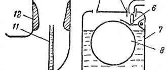
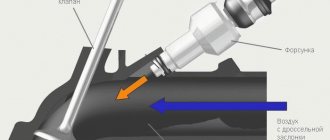
The main parts and components of a simple carburetor are: float chamber 7 with float 8 and shut-off needle 6, mixing chamber 1, diffuser 12, sprayer 11, jet 9 and throttle valve 2.
The required level of gasoline in the float chamber 7 while the engine is running is automatically maintained using the float 8 and the shut-off needle 6. When the gasoline level is low, the float drops and the needle 6 drops with it. The inlet opens and gasoline enters the float chamber. When the gasoline in the float chamber reaches a certain level, the float and with it the needle will rise so much that the needle closes the inlet and the flow of gasoline into the float chamber will stop.
Rice. Diagram of a simple carburetor: 1 - mixing chamber; 2 — throttle valve; 3 - hole connecting the float chamber with the atmosphere; 4 — needle valve seat; 5 — input channel; 6 - locking needle; 7 - float chamber; 8 — float; 9 — jet; 10 — air pipe; 11 - sprayer; 12 — diffuser
The float chamber is connected through a nozzle 9 to a spray nozzle 11. The nozzle has a calibrated hole through which a strictly defined amount of gasoline can flow per unit time.
Sprayer 11 is a tube with a hole for the outlet of gasoline. The gasoline in the sprayer and the float chamber is at the same level when the engine is not running. The gasoline level in the carburetor is adjusted so that it is below the upper end of the nozzle.
The float chamber is connected to the atmosphere through hole 3. If the engine is not running, then there will also be atmospheric pressure in the diffuser 12 and gasoline will not flow out of the atomizer.
Using the throttle valve, the amount of combustible mixture entering the engine cylinders is changed: the more the throttle valve is open, the more mixture enters the cylinders. The throttle valve is usually controlled using a foot pedal, as well as a button located on the instrument panel.
The carburetor is connected to the intake manifold with its mixing chamber 1.
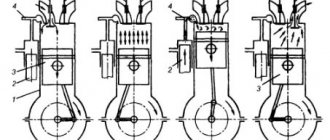
The process of formation of a flammable mixture in the carburetor occurs as follows. During the intake stroke, the piston in the cylinder moves to bottom dead center and draws air through the intake manifold and carburetor. The flow area of the diffuser 12 is smaller than the sections of the air pipe 10 and the mixing chamber 1, so the air passes through the diffuser at high speed.
As a result, in the zone of greatest narrowing of the diffuser, where the atomizer is located, thinner gasoline is created and begins to flow out of the atomizer. Gasoline flowing from the atomizer is captured by the air flow and passes with it into the mixing chamber. In this case, gasoline is sprayed into tiny droplets, partially evaporates and mixes with air.
The evaporation of gasoline and its mixing with air continues in the intake manifold and in the engine cylinders.
A car engine usually operates in variable mode, since the power and speed of its crankshaft must change depending on the driving conditions of the car. In accordance with this, the quantity and composition of the combustible mixture supplied to the cylinders must be changed.
When starting a cold engine, the carburetor must prepare a rich combustible mixture, since gasoline in this case evaporates poorly and to ensure starting it is necessary to increase the supply of gasoline.
When operating at medium loads, the engine must operate most economically, for which the carburetor must prepare a lean mixture; a slight drop in power in this case does not affect the vehicle's driving mode.
The greatest engine power can be obtained if a large amount of rich mixture is supplied to the cylinders. Therefore, when the throttle valve is fully opened, the carburetor must prepare a rich mixture. An enriched mixture is also necessary for a sharp increase in engine crankshaft speed, since it burns in the cylinder faster than a normal combustible mixture.
The simplest carburetor discussed above does not provide the necessary change in the composition of the combustible mixture depending on changes in engine operating mode.
In the simplest carburetor, at low throttle opening, a small amount of air passes through it; the speed of air movement through the diffuser is so low that the vacuum in the diffuser is insufficient for the required amount of gasoline to flow from the atomizer, and the mixture turns out to be lean.
When switching from low engine idle speed to medium load mode with increasing vacuum in the diffuser, gasoline consumption increases to a greater extent than air consumption, and the combustible mixture becomes excessively rich.
As the throttle valve opens further, gasoline consumption changes in proportion to air consumption, the composition of the mixture remains constant, and the simplest carburetor does not provide the necessary enrichment of the combustible mixture when the throttle valve is fully opened.
To ensure the required composition of the combustible mixture at various engine operating modes, modern carburetors have additional devices:
- main dosing system
- idle system
- economizer
- accelerator pump
- starting device
Main dosing system
The main metering system ensures a gradual depletion of the combustible mixture as the vacuum in the diffuser increases, as a result of which, at medium loads, the engine operates on an economical combustible mixture.
Rice. Diagram of a carburetor with a compensation jet: 1 - throttle valve; 2 - calibrated hole; 3 — compensation jet sprayer; 4 - compensation jet; 5 - compensation well; 6 - main jet; 7 — main jet sprayer; 8 — diffuser
Modern carburetors use metering systems with a compensation jet, emulsifying gasoline in a spray nozzle, and regulating the vacuum in the diffuser. In a carburetor with a compensation jet, the required composition of the combustible mixture is obtained using two jets: main 6 and compensation 4.
In such a carburetor, changes in the composition of the combustible mixture depending on the engine operating mode are carried out by a compensation jet system.
Sprayer 3 communicates with an additional, i.e. compensation, well 5, into which gasoline enters through compensation nozzle 4.
The compensation well communicates with the atmosphere, and therefore an almost constant amount of gasoline enters the well through the compensation jet, depending on the difference in levels in the well and the float chamber.
When the engine is running, with increasing throttle opening, the gasoline consumption through the main jet increases, and the gasoline consumption through the compensation jet remains almost unchanged. The total amount of gasoline flowing from both nozzles increases to a lesser extent than the air flow, and the combustible mixture becomes leaner.
The depletion of the combustible mixture is also facilitated by the influx of air sucked in through the compensation well and passing along with gasoline through the atomizer.
The flow sections of the main and compensation jets are selected to ensure an economical composition of the combustible mixture when the engine operates at medium loads.
The diagram of a dosing system with gasoline emulsion in a sprayer is shown in the figure.
Gasoline from the float chamber through the main jet 8 enters the well 4. The well communicates with the atmosphere through the air jet 3 and the emulsion tube 5 with several holes in the lower part.
When gasoline leaves the well through sprayer 2, a vacuum occurs in the well. As a result, gasoline begins to flow into the well through the main jet 8 and air through the nozzle 3. Gasoline and air are mixed in the well and exit through the sprayer in the form of an emulsion. As the vacuum in the diffuser increases, the consumption of gasoline from the well increases to a greater extent than its influx through nozzle 8. The level of gasoline in the well decreases, the number of open holes in the emulsion tube and the amount of air entering the well increase.
As a result, gasoline consumption with increasing vacuum in the diffuser increases more slowly than in a simple carburetor, and the combustible mixture becomes leaner.
The sections of the main and air jets are selected such that the composition of the combustible mixture when the engine is operating at medium loads is economical.
The diagram of a carburetor, in which the required composition of the combustible mixture is provided by a dosing system with automatic control of the vacuum in the diffuser, is shown in the figure.
Rice. Scheme of a dosing system with emulsification of gasoline in a sprayer: 1 - air to tubes; 2 - sprayer; 3 — air jet; 4 - well; 5 - emulsion tube; o - air holes; 7 - float chamber; 8 — main jet; 9 — throttle valve; 10 - diffuser
This type of carburetor has two or three diffusers, two jets and two nozzles. Four elastic plates 4 are attached to the bottom of the large diffuser 1, which with their lower ends are pressed against the middle diffuser 3 and close the passage between the large and middle diffusers. In the neck of the small diffuser 2 there is a sprayer 7 of the main jet 5. The main amount of gasoline passes through the main jet. In the neck of the large diffuser 1 there is an atomizer 8 of an additional jet 6.
The amount of gasoline supplied through the nozzles depends on the vacuum in the diffusers.
The composition of the combustible mixture is controlled by the main jet 5 due to the fact that the vacuum in the small diffuser does not change in proportion to the total air flow.
When the throttle is opened slightly and a small amount of air passes through the carburetor, all air flow is directed through the small and medium diffusers. In a small diffuser, a vacuum is created such that an amount of gasoline sufficient to obtain an enriched mixture emerges from the main jet atomizer.
Rice. Diagram of a carburetor with automatic control of vacuum in the diffuser: 1 - large diffuser; 2 — small diffuser; 3 — middle diffuser; 4 - elastic plate; 5 - main jet; 6 — additional jet; 7 — main jet nozzle; 8 — additional jet sprayer
As the throttle opening increases or the engine speed increases, the amount of air passing through the carburetor increases.
Under the influence of air pressure, the plates 4 bend and part of the air passes past the small diffuser. The greater the air flow, the more the plates move apart and the more air passes past the small diffuser. As a result, the vacuum in the small diffuser does not increase in proportion to the increase in air flow; Gasoline flow through the main jet decreases compared to the total air flow, and the combustible mixture becomes leaner.
With the correct selection of both jets, in almost all engine operating modes you can obtain a combustible mixture of the desired composition.
Comparison of mono injection and carburetor system
Mono-injection is one of the types of electronic fuel injection systems into the engine. We can say that single-injection systems are a kind of transitional model from a carburetor to an injector.
For the first time, mono-injection was developed and installed for aircraft as a more modern modification of the carburetor unit, which eliminated “failures” in the fuel supply during the performance of figures in the air.
A significant difference between a mono-injection and a carburetor system can be considered the presence in a mono-injection device of a computer unit for controlling the supply and consumption of fuel, as well as a gasoline pump and one injector powered by electricity. The mono-injection type of operation is similar to a carburetor, only using more modern components.
The main advantage of the mono-injection system is the uninterrupted operation of the engine, since a minimum pressure of 1 bar is constantly maintained in the unit. That is, vehicles with single injection can operate uninterruptedly during sudden overtaking or braking, when carburetor mechanisms cannot always guarantee engine stability in these modes.
In addition, mono-injection guarantees an increase in the power of the power unit due to the absence of power failures.
However, carburetors are still considered more economical devices to this day, since fuel injection is carried out not at one point, but throughout the entire chamber, which allows the entire incoming volume of fuel to be used. For this reason, engines with carburetors are easier to start in winter.
Thus, carburetor devices have good characteristics in terms of economical fuel consumption and the ability to start in any climatic conditions. Single injection ensures more stable engine operation and high quality vehicle power.
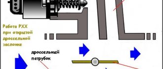
Idle system
When the engine is idling, in order to save fuel and reduce wear on engine parts, they strive to keep the crankshaft speed to a minimum. At idle, the engine operates with the throttle valve almost completely closed. In this case, the air flow is small, and the vacuum in the diffuser is not enough to supply air; the required amount of gasoline from the main dosing system.
The required composition of the combustible mixture for this engine operating mode is provided by the idle system. Gasoline flows through jet 2 into emulsion channel 7, located in the carburetor body. Air enters the same channel through jet 1. Air and gasoline are mixed and come out of hole 9 in the form of an emulsion.
In modern carburetors, in order to smoothly transition from idle speed to medium speed, there are two holes 8 and 9 for the exit of the emulsion. Hole 8 is located in front of the throttle valve, and the other hole 9 is behind it. When the throttle valve is closed, the emulsion exits through hole 9, and through hole 8 air is additionally sucked into the emulsion channel 7.
When the throttle valve is smoothly opened, a vacuum is also created near hole 8 and the emulsion begins to emerge from it, which ensures the required quantity and proper composition of the combustible mixture.
As the throttle valve opens, airflow increases; Accordingly, the vacuum in the diffuser and the flow of gasoline from the main jet increase. The carburetor switches from the idle system to the main metering system.
Rice. Idle system: 1 - air jet; 2 — idle jet; 3 - main jet; 4 — idle speed adjustment screw; 5 — lever on the throttle axis; 6 — screw for adjusting the composition of the combustible mixture; 7 — emulsion channel; 8 and 9 - holes for emulsion outlet; 10 - throttle valve
The amount of emulsion supplied by the idle system is regulated by screw 6, with the help of which the flow area of hole 9 is changed. When the screw is screwed in, the amount of emulsion decreases, and when turned out, it increases.
The engine crankshaft speed at idle is adjusted by changing the opening value of the throttle valve 10 using screw 4.
Pros and cons of carburetor
The main advantage is considered to be the affordable price of repairs. The next positive point is that the carburetor is not afraid of contamination and water ingress.
However, not everything is so smooth, because this mechanism needs to be cleaned and adjusted quite often. During the cold season, condensation may accumulate and freeze in the device body. In hot weather, the mechanism can easily overheat, which will lead to intense evaporation of fuel and a drop in engine power. The final argument against the carburetor is considered to be the high toxicity of the exhaust, which led to the refusal of its use in current cars.
Economizer
The main metering system of the carburetor is adjusted so that at medium loads the engine runs on an economical mixture. At maximum load conditions, an enriched mixture must be supplied to the engine cylinders. Enrichment of the mixture is provided by an additional carburetor device - an economizer.
The economizer valve 7 is pressed against the seat by a spring 9 and opens under the pressure of a rod 5, which has a piston 3 at the upper end. The piston is placed in a cylinder 4, the lower cavity of which is connected to the air pipe, and the upper cavity is connected to channel 8 with a mixing chamber behind the throttle valve.
The piston with the rod, under the action of spring 2, tends to occupy the lower position. When the throttle valve is opened slightly, a large vacuum is created behind it, which is transmitted through channel 8 to the upper cavity of the economizer cylinder. Under the influence of vacuum, the piston compresses spring 2 and takes the upper position. Valve 7 closes the inlet.
With an increase in the opening of the throttle valve, the vacuum in the air pipe decreases so much that under the action of spring 2, piston 3 will go down, rod 5 will press on valve 7, which will open the inlet hole, and an additional amount of gasoline will begin to flow from the float chamber through nozzle 10 into sprayer 1 - the mixture enriches itself.
Main problems with the carburetor
Among the most common malfunctions in the operation of the carburetor are the following:
- fuel leak
- carbon deposits and smell on spark plugs
- unstable idle
- violation of carburetor adjustment, contamination of jets
Fuel leak
First you need to check the gasoline pressure - it corresponds to the mark from 4 to 7 psi.
Presence of carbon deposits and odor on spark plugs
This problem indicates that fuel is being supplied in excessive quantities due to an incorrect gasoline level or a burnt-out valve.
Rough idle
Basically, problems of this nature arise in the wiring between the accelerator pedal and the carburetor, that is, not specifically in the carburetor.
Improper carburetor adjustment, contamination of jets and channels
The main role in preparing the air-fuel mixture is played by jets - their contamination or damage leads to malfunction
the entire node.
With such malfunctions, the engine is not able to receive fuel in the required concentration and volume. Signs of this are:
- excessive fuel consumption;
- reduction in car engine power;
- black smoke is emitted from the muffler and popping noises are heard;
- the engine begins to overheat;
- The viscosity of automobile oil decreases.
Acceleration pump
The accelerator pump is designed to briefly enrich the combustible mixture when the throttle valve is opened sharply.
Rice. Diagram of an economizer with a pneumatic drive: 1 - sprayer; 2 - spring; 3 - piston; 4 - cylinder; 5 - rod; 6 - main jet; 7 — economizer valve; 8 - channel; 9 — valve spring; 10 — economizer jet
In the carburetor body there is a cylinder 8 in which the piston 7 of the pump is placed. The cylinder is connected to the float chamber by a channel, at the beginning of which there is a check valve 9. The outlet channel has a needle valve 10.
The piston is driven by the throttle valve drive mechanism through lever 13, driver 12, rod 11 and pressure plate 4, which acts on the piston through spring 5. When the throttle valve is smoothly opened, the pump piston slowly lowers and gradually squeezes gasoline from the cylinder into the float chamber through the open check valve 9.
When the throttle valve is opened sharply, the piston quickly lowers and squeezes gasoline out of the cylinder. In this case, gasoline lifts the check valve, which closes the inlet, preventing gasoline from escaping back into the float chamber. Gasoline, lifting the needle valve 10, is injected through the nozzle 3 into the carburetor mixing chamber and enriches the combustible mixture.
What is a carburetor, purpose
The carburetor is one of the most complex parts of the fuel concept of any gasoline device. Its purpose is to produce a fuel-air mixture (FA) by saturating gasoline with oxygen in the required quantities and then feeding the finished mass into the cylinders. Mixing of all components is carried out in the desired consistency corresponding to the operating modes of the engine.
The fuel supply procedure is carried out exclusively thanks to the carburetor, which has a mechanism such as a diffuser. It is designed to narrow the air throat of the mechanism. In other words, during the passage of the atmosphere through this narrowing, a decrease in pressure occurs. Then a small opening is used to supply fuel. Under high pressure, fuel is squeezed out of the chamber into the neck of the carburetor, from where the mixture is directed into the outlet channel and then enters the engine cylinders.
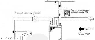
Starting device
The most common device for enriching the combustible mixture when starting the engine is the air damper 12 installed in the carburetor air pipe.
When starting the engine, open the throttle valve slightly and close the choke valve. As a result, when cranking the engine crankshaft, a strong vacuum is created in the carburetor and gasoline flows out of all jets - the combustible mixture becomes richer.
The air damper has a safety valve 11, which opens automatically as soon as the engine starts running.
The air damper is controlled using a button located on the instrument panel and connected to the damper by a flexible rod.
Rice. Diagram of an accelerator pump with a mechanical drive: 1 - air pipe; 2 - air channel; 3 — accelerator pump nozzle; 4 - pressure plate; 5 - spring; 6 - rod; 7 - piston; 8 - cylinder; 9 - check valve; 10 — needle valve; 11 - thrust; 12 - leash; 13 - lever
As the engine warms up, the choke valve is gradually opened. Operation of the engine with the air damper closed should be as short as possible, since a strong enrichment of the combustible mixture during operation of a cold engine causes increased wear.
Advantages and disadvantages of a carburetor
The main advantage of a carburetor is its maintainability. You can purchase a repair kit for this device, which can be replaced, if necessary, even on the street. However, this advantage has long lost its practical meaning: the development of computer diagnostics has made injector repair an activity almost equivalent in simplicity. The diagnostic program can even be installed on an iPhone, and errors can be successfully read using an adapter cable.
The disadvantages of a carburetor are due to the fact that it is a rather thin and complex mechanical device. It must be adjusted from time to time, cleaned and protected from blockages. In addition, its operation depends on weather conditions: in winter, condensation can freeze in it, in summer it overheats, and the fuel begins to evaporate rapidly. In general, we can say that this device is morally outdated.
Maximum speed limiter
Operating the engine at crankshaft speeds above the maximum permissible limits leads to excessive fuel consumption and increased wear of engine rubbing parts. To avoid this, car engines are often equipped with pneumatic speed limiters.
Throttle valve 4 has a shaped shape with a beveled plane of the left half, and its axis is shifted by 1.5-2 mm relative to the axis of the mixing chamber.
A spring 9 is attached to the damper, which tends to hold the damper in the open position.
When the engine is running, the air flow acts on the throttle valve and, since the upper plane of its left half is beveled and the axis is shifted to the right, it tends to close the valve.
When the number of revolutions of the crankshaft becomes higher than the permissible speed, the pressure of the air flow on the left side of the damper increases so much that the damper, overcoming the resistance of the spring, closes, a smaller amount of combustible mixture is supplied to the cylinders and the engine crankshaft speed decreases.
Rice. Engine crankshaft maximum speed limiter: 1 - foot; 2 - nut; 3 - fitting; 4 — throttle valve; 5 - rod; 6 — needle bearing; 7 — throttle axis; 8 — earring; 9 - spring; 10 - gasket; 11 — cap; 12 — hairpin
The speed limiter operates independently of the throttle pedal. When the pedal is released, the throttle valve is closed under the action of the pedal return spring, which is much stronger than the speed limiter spring.
When you press the pedal, the throttle valve is released from the action of the pedal return spring and opens due to the tension of its spring.
By changing the tension of spring 9 by rotating the adjusting nut 2, you can adjust the maximum number of revolutions of the engine shaft.
Let's consider the design and operation of carburetors installed on the engines of some domestic cars.
A little history
Early developments at the dawn of the engine building era used lighting gas as fuel. At an early stage, such engines simply did not need a carburetor. The illuminating gas entered the cylinders due to the vacuum that was formed during engine operation. The main problem with such fuel was its high cost and a number of difficulties during use.
The second half of the 19th century was the period when inventors, engineers and mechanics all over the world tried to replace expensive lighting gas with a more economical, cheaper and accessible type of fuel for the internal combustion engine. The best solution was to use liquid fuel that is familiar to us today. It is worth considering that such fuel cannot ignite without the participation of air.
To prepare a mixture of air and fuel, an additional device was required. Not only that, but it was also necessary to mix air with fuel in the required proportions. To solve this problem, the first carburetor was invented. The device was released in 1876. The creator of an early model of the carburetor was the Italian inventor Luigi De Christoforis. In its design and operating principle, the first carburetor had a number of significant differences from more modern analogues.
Carburetor K-22D
Carburetor K-22D , installed on the engine of the GAZ-69 car, is a three-diffuser carburetor.
The main dosing system of the carburetor operates on the principle of regulating the vacuum in the diffuser. It consists of a main jet 27, the nozzle of which goes into the small diffuser 10, an additional nozzle 25, the nozzle of which goes into the neck of the large diffuser 14, and an automatic bypass air valve, consisting of four elastic plates 5.
The amount of gasoline passing through the main jet can be adjusted depending on the operating conditions of the engine using needle valve 26.
Rice. Carburetor K-22D: 1 - flange; 2 — screw for adjusting the idle mixture quality; 3 - hole for the emulsion to escape during the transition from idle speed to medium speed of the engine crankshaft; 4 - hole for vacuum regulator; 5 - elastic plate; 6 — idle jet; 7 — middle diffuser; 8 — emulsion idle jet; 9 — idle air jets; 10 — small diffuser; 11 — air damper safety valve; 12 — air damper; 13 - tube; 14 - large diffuser; 15 — accelerator pump nozzle; 16 — sprayers; 17 — discharge valve of the accelerator pump; 18— accelerator pump piston; 19 — check valve; 20 - float; 21 - locking needle; 22 — float chamber body; 23 — accelerator pump piston drive rod; 24 — economizer valve; 25 — additional jet; 26 — needle valve of the main jet; 27 - main jet; 28 — economizer jet; 29 - throttle valve
The idle system consists of an idle jet 6, two air jets 9 and an emulsion jet 5.
The economizer and accelerator pump are combined into one system, consisting of an accelerator pump with a piston 18, a pump discharge valve 17, a jet 15, a check valve 19, a jet 28 and an economizer valve 24. The accelerator pump is driven mechanically by the throttle valve.
The float chamber communicates through tube 18 with the air pipe, and not with the atmosphere, as a result of which the influence of the air filter resistance on the operation of the carburetor is eliminated.
When the engine is running at low idle speed, the throttle valve is closed. Due to the high speed of air movement through the narrow gap between the damper and the walls of the mixing chamber, a vacuum is formed in the throttle valve area.
Since the outlet of the idle system is located in this area, the vacuum is transferred to the system and it operates as an independent carburetor.
Gasoline from the float chamber enters the idle jet 6 through an additional jet 25 through the carburetor channels. Having passed the idle jet, the gasoline rises and, meeting the air entering through the air jet 9, mixes with it and passes through the emulsion jet 8 in the form of an emulsion.
Coming out of the emulsion nozzle, gasoline again meets the air flow passing through the air nozzle and is mixed with it. The emulsion exits through the idle hole behind the throttle valve.
The emulsion consumption and, consequently, the quality of the combustible mixture at idle is adjusted by screw 2.
When the engine is running and at medium loads (the throttle valve is open approximately halfway), the vacuum in the diffusers increases so much that the bulk of gasoline comes out of the nozzles of the main 27 and additional 25 nozzles.
As the air flow passing through the diffuser increases, the plates 5 of the air bypass valve diverge and the air flow passes by the small 10 and medium 7 diffusers, automatically adjusting the vacuum in the small diffuser and, consequently, the composition of the combustible mixture depending on the throttle opening value.
When the engine is running at full load, the throttle valve is fully open. In this case, the piston 18 of the accelerator pump is in the lower position and, pressing the economizer valve 24, opens access to an additional amount of gasoline, which from the float chamber passes through the economizer nozzle 28 to the additional nozzle atomizer.
When the throttle valve is opened sharply, the accelerator pump piston drops sharply and squeezes gasoline out of the cylinder. Check valve 19 closes, and valve 17 of the accelerator pump opens, and gasoline is released in a stream through jet 15 into the neck of large diffuser 14 - the combustible mixture is enriched.
When starting the engine, the combustible mixture is enriched by closing the air damper 12, which has a safety valve 11.
The K-22G carburetor, which is installed on the engines of GAZ-63 and GAZ-51 A cars, is also made according to the design of the K-22D carburetor.
Principle of operation
A simple carburetor is not able to provide the engine with a suitable mixture, according to its composition, at all stages of operation. In addition to the quantity of fuel assemblies, the car owner is obliged to manage its quality thanks to the “choke” handle connected to the atmospheric damper.
When the handle is pulled, the flap closes and less air enters the mixing chamber, and the vacuum is filled with fuel to the greatest extent. This fact is important, especially when starting the engine in the cold, when a rich mixture is needed, which can ignite at subzero temperatures.
The creation of a balanced fuel mixture in the mechanism chamber is not complete. Some of the fuel cannot evaporate and mix with the atmosphere. Drops of fuel that have not had time to evaporate move and settle on the walls of the chamber and exhaust pipes.
The fuel that settles on the walls forms a kind of film that moves at low speed. In order to evaporate the film of gasoline, the inlet pipes are heated during engine operation. Liquid heating or gas heating is more common. We can safely say that the generation of the combustible mixture ends at the end of the engine intake pipe.
Carburetor type K-82
Rice. Carburetor type K-82: 1 - flange; 2—emulsion channel; 3 - gasket; 4 — accelerator pump channel; 5 — accelerator pump valve; 6 — accelerator pump nozzle; 7 — small diffuser; 8 - annular slot; 9 — air pipe housing; 10 — air damper; 11 - safety valve; 12 — idle jet; 13 — economizer valve seat with pneumatic drive; 14 — economizer valve needle; 15 - hole through which the float chamber is connected to the air pipe; 16 — screw for adjusting the idle mixture quality; 17 — piston of the pneumatic drive of the economizer; 18 — pressure plate; 19 — economizer valve pusher with mechanical drive; 20 — accelerator pump piston rod; 21 - spring; 22 — filter plug; 23 - mesh filter; 24 - locking needle; 25 - gasket; 26 — float chamber body; 27 — float: 28 — accelerator pump piston; 29 - check valve; 30 — accelerator pump piston drive rod; 31 — rod driver; 32— economizer valve ball; 33 — accelerator pump drive lever; 34 — economizer valve spring; 35 — economizer valve seat; 36 - sealing ring; 37 — economizer piston spring; 38 — main jet; 39 - channel; 40 - plug; 41 — full power jet; 42 — throttle valve; 43 - emulsion tube; 44 — air jet; 45 - outlet
The K-82 type carburetor is a double-diffuser carburetor. It is installed on the engines of ZIL-164A and ZIL-164 cars.
The main metering device, operating on the principle of emulsifying fuel in a sprayer, consists of two fuel jets 38 and 41, an air jet 44 and a sprayer in the form of an annular slot 8 in a small diffuser. An emulsion tube 43 with holes is placed in the well of the main dosing device.
The idle system consists of an idle jet 12, channel 2 and an outlet 45 in the form of a slot. The quality of the combustible mixture at idle is regulated by screw 16, and its quantity by opening the throttle valve.
A piston-type accelerator pump with a mechanical drive from the throttle valve supplies fuel through channel 4 to nozzle 6.
The carburetor has two economizer valves. The mechanically actuated valve consists of a seat 35, a ball 32 and a spring 34, which presses the ball against the seat. A pneumatically actuated valve consists of a seat 13 and a needle 14, which is connected to a piston 17 of the pneumatic actuator. The piston, with the help of spring 37, occupies the upper position when the engine is not running. The space under the piston is connected by channel 39 to the mixing chamber behind the throttle valve.
When the engine is idling, the throttle valve is closed. The vacuum behind the throttle valve spreads through outlet 45 along channel 2 to idle jet 12. As a result, gasoline from the well of the main metering device flows to the idle jet. At the same time, air enters the nozzle. The mixture of gasoline and air, passing through the idle jet, enters the outlet.
Engine operation at medium speed. As the throttle valve opening increases, the air flow passing through the small diffuser increases, as a result of which the vacuum in the diffuser is sufficient for the main metering system to come into operation.
Gasoline from the float chamber flows through jets 38 and 41 into the well. Air also enters here through the nozzle 44 and holes in the emulsion tube 43. The mixture of gasoline and air exits through the annular slot 8 in the small diffuser.
The cross-sections of the fuel and air jets are selected so that a lean mixture is prepared at small and medium throttle openings. In these cases, both economizer valves are closed. The economizer valve with a mechanical drive is closed under the action of spring 34. The valve with a pneumatic drive is closed due to the vacuum in the cylinder under the piston 17. Under the influence of the vacuum transmitted from the mixing chamber, the piston occupies the lower position, compressing the spring 37. Together with the piston, it is in the lower position needle 14, which with its lower end is pressed against seat 13 and closes the fuel channel.
To prevent the vacuum from being transferred to the float chamber, piston 17 in this position sits on the sealing ring 36.
As the throttle valve opening increases, the vacuum under the piston of the pneumatic economizer decreases and the piston rises under the action of spring 37. When the vacuum behind the throttle valve decreases to a certain value (125 mm Hg), the piston and with it the needle 14 will rise so much that the needle opens the inlet hole of the nozzle and an additional amount of gasoline from the float chamber will begin to flow to the full power nozzle 41. The combustible mixture is slightly enriched, which is necessary during unsteady vehicle movement (for example, during acceleration, when the vehicle is moving on dirt roads and terrain).
The mechanically actuated economizer valve opens when the throttle valve is almost fully open.
When the throttle valve is opened, the rod 30 is lowered; when the valve is almost completely open, the plate 18 on the rod 30 presses on the pusher 19, which, when lowered, will open the ball valve. Benzene from the float chamber is additionally supplied to the full power jet 41, the cross-section of which is designed for preparing an enriched mixture.
When the throttle valve is opened sharply, the mixture is enriched by the accelerator pump. In this case, the piston drops sharply and gasoline is squeezed out from under the piston. Check valve 29 is pressed against the seat and closes the channel leading into the float chamber. Gasoline is supplied through channel 4 to jet 6 and flows out of it in a thin stream, enriching the combustible mixture. Enrichment of the combustible mixture when starting a cold engine is carried out by closing the air damper. The air and throttle valves are connected by drive rods so that when the air valve is completely closed, the throttle valve is slightly open. This enriches the mixture sufficiently and ensures reliable engine starting.
Strengths and weaknesses of the device
The main advantage of the carburetor is its affordable maintainability. To this day, there are special repair kits on the market that allow you to return the carburetor to operation quickly enough. Repairing a carburetor does not require an arsenal of any special equipment, and almost any motorist can repair the device if they have certain skills.
A mechanical carburetor is not so afraid of dirt and water, since their entry cannot completely damage it. This simultaneously conceals both the strength and weakness of the device. The carburetor needs to be adjusted quite often and must be cleaned compared to fuel injection, but it is more durable than electronic solutions when a number of conditions arise that are considered difficult or even extreme operating conditions.
Additional advantages of the carburetor include its less sensitivity to low-quality fuel, and the cleaning process does not seem difficult. Although the carburetor is a relatively complex device, it is definitely easier to diagnose problems and maintain it compared to a clogged or faulty injection system.
The last argument against the carburetor is the increased toxicity of the exhaust, which has led to the abandonment of its use on modern cars around the world. Today, the carburetor is justifiably considered a hopelessly outdated “classic” solution.
Features of adjusting the Solex carburetor. How to set the fuel level in the float chamber, adjust the idle speed, select jets, remove dips.
Carburetor cleaning: when to clean the metering device, signs and symptoms. Available methods for cleaning the carburetor without disassembling and removing it from the car.
Refinement and modernization of the carburetor. The main disadvantages of the carburetor injection system and how to eliminate them, settings. Intake manifold tuning.
Main dosing system, transition system in the secondary chamber, types of idle systems. Accelerator pump, economizer and cold start.
The main reasons that lead to a lean mixture. A lean mixture on carburetor and injection internal combustion engines, as well as on engines with gas equipment. Diagnostics, repair.
Various types of available carburetor cleaning products and compositions, advantages and disadvantages. How to properly clean a carburetor, which cleaner is better.
In order to work, a car engine needs power. Unlike electrical equipment, which is powered from the mains, a machine engine needs fuel, which is why cars have a special power system. It includes the fuel tank, fuel pump, fuel lines, carburetor, air filter, intake and exhaust pipes and muffler. One of the most important parts of the power system is the carburetor. In it, a combustible mixture is formed from fuel.
Development and production
In the history of the automotive industry, the caburator was designed and assembled in 1895 by a self-taught technician of German origin, Wilhelm Maybach. Carburetor engines, like the carburetors themselves, have changed more than once over the years, but the principle of their operation has remained unchanged. The technology of fuel evaporation, used in the first versions of carburetors to form a fuel-air mixture, in modern models has been replaced by fuel atomization technology, which has become the main difference and advantage of this vehicle unit.
Carburetors of a new design began to be mass produced in 1925 by the world famous Bosch concern. The reliability and safety of vehicles was improved by making changes to the design of carburetors related to the integration of the fuel pump and fuel injection system. Design changes to the carburetor made it possible to begin creating innovative power units running on diesel fuel. Ten years later, the first car equipped with a diesel engine rolled off the assembly line of the Mercedes plant.
The established production of injection engines began to require an increase in the power of gasoline engines. This was achieved through the introduction of an intake manifold, which provoked the start of production in the mid-40s of engines with a direct fuel injection system and a higher-power carburetor.
In 1965, the Bosch concern released a new version of the carburetor with a distributed fuel injection system onto the automotive market. The design of the carburetor was significantly changed and acquired an electric pump, which replaced the fuel injection pump, which resulted in a reduction in the cost and dimensions of the entire unit.
The first carburetor with a multipoint fuel injection system was released by Bosch
In 1994, Mitsubishi Motors introduced a direct fuel injection system into carburetor engines. This design solution had its advantages: fuel economy coupled with achieving maximum torque.