It often happens that the car is to blame for an engine failure, low-quality fuel that was spilled at a service station, although in fact the input shaft speed sensor in the automatic transmission has simply failed. Damage can be mechanical, destruction of the housing or internal seal, oxidation of contacts. But first things first.
Write in the comments, has this device already failed?
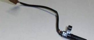
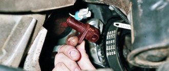
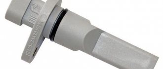
Automatic transmission input shaft speed sensor
The automatic transmission has two speed sensors.
- one sets the number of revolutions of the input shaft;
- the second one measures it.
Attention! When a vehicle's automatic transmission is retracted, a sensor measures the number of revolutions of the differential.
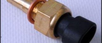
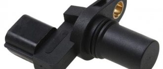
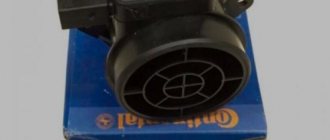
The input shaft sensor is a non-contact magnetic Hall effect device. Consists of a magnet and a Hall IC. This equipment is packaged in a sealed bag.
Information from these sensors enters the electronic control computer of the machine, where it is processed. If there is a malfunction of both the sensor and the crankshaft or differential, the automatic transmission goes into emergency mode.
If the ECU does not detect a problem based on the sensor readings and the vehicle speed decreases or does not increase and the test engine runs, then the automatic transmission input shaft sensor is most likely faulty. But we'll talk about this later.
Hyundai automatic transmission repair
Now I will talk about how the input shaft sensor works.
Principle of operation
As I already wrote, the device records the number of shaft revolutions after switching to one of the automatic transmission gears. The Hall sensor works as follows:
- During operation, the electromagnetic sensor creates a special electromagnetic field.
- When a wheel protrusion or a tooth of a “jog” gear installed in it passes through the sensor, this field changes.
- The so-called Hall effect begins to work. In other words, an electrical signal is generated.
- It is converted and supplied to the automatic transmission electronic control unit.
- Here it is read by a computer. A low signal is a trough and a high signal is a ridge.
The “impulse wheel” is a regular gear mounted on the tool. The wheel has a series of ridges and valleys.
Where is
The sensor for measuring the speed of the automatic transmission output shaft is installed on the car body next to the air filter. Devices for measuring the number of revolutions of the input and output shafts differ in the number specified in the catalog. Hyindai Santa vehicles have the following catalog values: 42620 and 42621.
Attention! These devices should not be confused. There is a lot of information about these devices on the Internet, but often inexperienced writers do not distinguish between them and write about the same thing. For example, information from the latter device is needed to adjust the lubricant pressure. These automatic transmission sensors have different proportionality between the RPM and the signals coming from them.
It is these devices that directly communicate with the automatic transmission control unit. The devices themselves are repairable. All that remains is to check if there are any cracks on the body.
Mercedes automatic transmission torque converter repair
Next, I’ll tell you about diagnosing problems with the sensor for measuring the number of revolutions of the input shaft.
Diagnostics
If you are a novice car enthusiast and don’t know how to check and where to start looking for errors in the device, I recommend making the contacts ring and measure DC or AC signals. For this you use a multimeter. The instrument is used to determine voltage and resistance.
Diagnosis can be made by the shocks and jolts that the driver feels when shifting the gear lever to “D” mode. A faulty sensor produces incorrect rotational measurements and results in low or excessive pressure, resulting in a drop in acceleration during acceleration.
Experienced mechanics refer to visual diagnostics, observing the appearance of errors on the dashboard monitor. For example, the following indicators on the monitor may indicate problems with the input shaft sensor:
- Check engine";
- "Hold" indicator flashes."
The automatic transmission may go into emergency mode or engage only 3rd gear and no more.
If you are testing the scanner with a laptop computer, the following error "P0715" will be displayed. In this case, it is necessary to replace the automatic transmission input shaft sensor or replace damaged wires.
Additional comments for troubleshooting P0715
Trouble code P0715 can appear not only in vehicles with a traditional automatic transmission, but also in some vehicles with a continuously variable transmission.
Need help with error code P0715?
The company - CarChek, offers a service - on-site computer diagnostics; specialists from our company will come to your home or office to diagnose and identify problems with your car. Find out the cost and sign up for computer diagnostics of your car or contact a consultant by phone +7(499)394-47-89
Information about the operating mode of the automatic transmission is collected and transmitted by automatic transmission sensors. Based on the data received, the electronic control unit creates the necessary control signal, for example, selecting the optimal gear ratio. Failure of the sensors is signaled by the check engine lighting up. In this case, the car may accelerate poorly, drive with large dips during gear changes, and refuse to budge. Malfunctions can occur both in one selector position and in all modes.
Measuring the rotation of the automatic transmission output shaft
Previously, I wrote about a sensor for measuring the rotation of the output shaft of an automatic transmission, comparing it with a device that records the rotation speed. Now let's talk about its malfunctions.
A faulty output shaft speed sensor is identified by code P0720. The ECU receives the signal from the device and decides at what speed to activate the next one. If there is no signal from the sensor, the automatic transmission goes into emergency mode, or an experienced mechanic diagnoses error 0720 using a scanner.
Dismantling, washing and repair of the valve body of the automatic transmission 5cv19
But first, the driver may complain that the car is stuck at one speed and does not change gears. Drops during acceleration are observed.
Write in the comments if you had problems with the devices for determining the rotation speed of the input and output shafts, what errors the automatic transmission gave you.
Product description FORD 1850527
The Part-auto online auto parts store works directly with the FORD central warehouse, which gives you a 100% guarantee of purchasing truly original spare parts. Available FORD spare parts are focused on the most popular models of automobile brands: Ford. Spare part 1850527 can be used in several modifications and models. To clarify applicability, you must send a VIN request and our specialists will check the compliance of the spare part with your car.
You can buy an original spare part “Input shaft speed sensor, automatic transmission Powershift / FORD 10
» with the brand name “FORD” with delivery of the purchased goods to 2200 pick-up points or order courier delivery. The online auto parts store Part-auto.ru currently offers 0 analogue offers and 0 replacement offers from the supplier “FORD”. This part is used for installation on cars of the following brands: Ford.
Minimum cost of the spare part “Input shaft speed sensor, automatic transmission Powershift / FORD 10
» is 12,959 rubles. The fastest delivery for trade offers is 2 days.
Gear shift detection
Now you know everything about the sensors that control the rotation speed of the input and output shafts. Let's talk about another important device - a device for determining gear shifts. It is located next to the selector. The choice of speed and the driver’s ability to engage a certain gear depend on this.
This device controls the position of the gear selector rocker arm. But sometimes it fails, and then the driver notices:
- incorrect designation of the selected gear on the dashboard monitor;
- the letter of the selected gear is not displayed at all;
- the transition from one speed to another occurs jerkily;
- gear shift activation delay. For example, a car may stand still for some time before driving in a certain mode.
All these malfunctions arise due to:
- drops of water enter the housing, immediately breaking the seal;
- dust on contacts;
- wear of contact plates;
- oxidation or contact contamination.
To correct errors caused by improper operation of the sensor, the device must be disassembled and cleaned. To clean the contacts, use regular gasoline or kerosene. If you need to solder loose pins, solder them.
Read moreDiagnostics and repair of automatic transmission selector position sensor
Use a penetrating lubricant to clean the contacts. But experienced mechanics and I do not recommend lubricating the surface with Lithol or Solid Oil.
Automatic transmission design
We will not delve deeply into the design features of the automatic transmission - we will mention them only briefly.
So, there are five main elements in total:
- The gearbox itself with a set of gearboxes;
- Hydraulic transformer (plays the role of a conventional clutch);
- Gear shift mechanism (friction clutches, brake band and other elements);
- Distribution block (through it, oil is supplied to the hydraulic pushers, which “push” the gear selection mechanism).
- There is also an automatic transmission control unit - this is the main computer of the car. Its task is to set the hydraulic part in motion based on the readings of the vehicle sensors.
Features of obtaining data on the position of selectors in some car models
The following car modifications have working sensors:
- Opel Omega. The strips on the selector position sensors are thick. Therefore, they rarely fail. If they break, light solder reconnects the contacts;
- Renault Megane. Car owners of this car may experience a jammed input shaft sensor. Since cardboard is packaged in fragile plastic, which very often melts when exposed to high temperatures;
- Mitsubishi. Mitsubishi automatic transmission input shaft sensors are known for their reliability. To correct their poor performance, it is necessary to disassemble it and blow it with air, and clean the contacts with kerosene.
If cleaning and bleeding the automatic transmission input shaft sensors does not help, they need to be replaced. Have you ever replaced such devices? If not, relax. I'll tell you how to do it yourself.
Automatic transmission Ford / Mazda F4A-EL, 4EAT-F (Mazda, Ford, Kia)
The 4-speed automatic transmission F4A-EL (Kia - 4EAT-F, F4E-AT ) was developed by Mazda engineers in collaboration with Jatco in 1989 for front-wheel drive cars with an engine of approx. 1.6 liters. It was designed to replace the 3-speed automatic transmission F3A and was installed on Kia, Mazda 323, Ford Escorts (list below). Structurally related to its older brother 4EAT-G .
In the early years, childhood illnesses appeared, solving which, the designers changed the hydraulic plate, introduced a new solenoid instead of the kick-down cable, replaced some washers and bearings, and for Mazda Protégé, as well as for Fords, since 1998, hydraulic units began to be produced in a different modification.
In 1997, Kia chose to modify the F4A-EL for the Mazda 323.
Most often, the F4A-EL automatic transmission is found in services such as 4EAT-F with Kia Rio and Spectra cars.
Since the beginning of the new century, Ford has replaced this rather successful (in terms of comfort and price) transmission with the no less successful (simple and repairable) 4F27E.
Valve body filters for F4A-EL have three modifications:
— With a deep sump and intake pipe (for our rare AWD SUVs) No. 244010A.
— And a filter without an oil intake pipe (the most popular) with a shallow pan (244010) on the right. Filters through a metal mesh, “coarse” filter.
Replacing the automatic transmission input shaft sensor
Attention! In rare cases, drivers of Renault Megane 2nd generation and other vehicles may not notice any changes in the operation of the automatic transmission. The gradual increase in this problem will lead to the fact that the car may go into emergency mode somewhere in the middle of heavy traffic. This will create an emergency situation. Therefore, it is important to return the car to the service center for maintenance on time.
Repair and replacement of a failed output shaft speed measurement sensor is carried out in the following sequence:
- Open the hood and remove the air filter to get closer to the device.
- Disconnect it from the connectors.
- Check the housing for leaks. If everything is fine, open the device.
- Check the voltage and resistance of the device.
- If the gear teeth are worn, replace it with a new one.
- Check the contacts and clean them.
- If the device is in poor condition, replace it and install a new one.
- After all procedures for installing a new one are completed, check the automatic transmission for errors with a scanner.
- If errors persist, check the terminals and cables. They can be bitten by mice or cats.
- Replace them if necessary.
Read The experience of replacing a robotic gearbox with an automatic Toyota Corolla
After replacing the components and cables, start the car and move the gearbox selector lever, increase the speed to 40 km/h. Look at how the switching occurs, whether the letters on the monitor correspond to the gear engaged.
If everything is ok, you were able to diagnose the problem and fix it. If not, contact your nearest service center.
Malfunctions of automatic transmission solenoids - Symptoms and causes
The solenoids currently used in automatic transmissions are reliable and durable. However, it would be wrong to say that this element is completely free of any problems or breakdowns. Like any other mechanical element, the solenoid can break down and fail. We will describe the most common breakdowns and their causes.
For example, quite often there is an increase in oil deposits and fine dust on the metal core. As a result, the core does not extend into the rod even when receiving the necessary electrical signal. At operating oil temperature in the gearbox, the solenoid may jam, and the car will display an error in the operation of the gearbox. This problem can be eliminated by washing the solenoids in special solvents. Solenoid block
Pinout of connectors on Mitsubishi
1) Connector type No. 1 - 12-pin rectangular connector
Brand and year (approximately): all models 1989-1998.
Typical location: in the cabin under the dashboard on the driver's side.
Appearance:
Video review of OBDII diagnostic connectors
Assignment of diagnostic connector pins:
1 - Engine - MPI - Engine management system (for the main diagnostic connector, white). ABS/ASR control system (for additional diagnostic connector black) 2 - Steering - 4WS - Steering system 3 - Suspension - Active ECS - Suspension control system 4 - Brake - ABS - Anti-lock braking system 5 - Cruise Control - ASC - Cruise control system control 6 - Transmission - ELC-4/5AT - Automatic transmission control system 7 - Air Conditioner - Full Auto AC - Air conditioning control system 8 - Air Bag - SRS - Passive safety system (airbags, belt pretensioners) 9 - ETACS: Pulse signal only — Electrical control system 10 — Diagnosis Control (In 6G72 MPI SOHC, Mirage 1.5L,1.8L short to GND if check and adjust idle or connect the voltmeter positive probe for read DTC ECS) 11 — Output for simulating the speed sensor signal 12 — Ground
Examples of connector location on selected Mitsubishi car models
- Mitsubishi Eclipse (1991-1995) Location: under the dashboard, near the driver’s right foot
2) Connector type No. 2 - 12-pin rectangular and 16-pin trapezoidal connectors
Makes and years (approximately): some models 1994-2002.
Typical location: in the cabin under the dashboard on the driver's side.
Appearance:
Assignment of diagnostic connector pins:
1 - Diagnosis control line - All serial data transmission from electronic control units 2 - J1850 (+) line 3 - Suspension - ECS - Suspension control system 4- Ground (battery) 5- Ground (signal) 6- Transmission - ELC- 4/5AT — Automatic transmission control system 7 — K-line diagnostics (ISO 9141) — Engine control system 8- Brake – ABS — Anti-lock braking system 9- ETACS: Pulse signal only — Electrical control system 10- J1850 (-) line 11- Air Conditioner — Full Auto AC - Air conditioning control system 12- Air Bag - SRS - Passive safety system (airbags, seat belt pretensioners) 13- Cruise Control - ASC - Cruise control system 14- Vehicle speed signal - Output for simulating the vehicle speed sensor signal 15 - L- diagnostic line (ISO 9141) 16- Power supply +12V from the battery 21- Traction – TCL/4WD – Traction control system and traction control system (torque control) 22- Steering – 4WS/ECPS – Steering system 25- Engine management system 26- Output for reprogramming the engine ECU 27- Output for reprogramming the automatic transmission ECU 32- Adapter identification - Cable identification contact
Examples of connector location on selected Mitsubishi car models
- MitsubishiSpace Star (1999-2003) Location: cups in front of the gearshift knob under a plastic plug with recesses
- MitsubishiPajero (after 2004 inclusive) Location: under the dashboard, near the driver’s right foot
To diagnose Mitsubishi cars with a similar connector, you must use an OBD II 16-pin Mitsubishi 12 Pin adapter
3) Connector type No. 3 - 16-pin OBD-II connector in the shape of a trapezoid
Makes and years (approximately): some models after 1996
Typical location: in the cabin under the dashboard on the driver's side.
Appearance:
Assignment of diagnostic connector pins:
2 - J1850 Bus+ 4 - Body ground 5 - Signal ground 6 - CAN-High line, J-2284 7 - K-line diagnostics (ISO 9141-2 and ISO/DIS 14230-4) 10 — J1850 Bus- 14 — CAN-Low line, J-2284 15 — L-diagnostic line (ISO 9141-2 and ISO/DIS 14230-4) 16 — +12V power supply from the battery Examples of connector location on certain Mitsubishi car models
- MitsubishiGalant (1997-2003) Location: under the dashboard, near the driver’s right foot
OpenECU – Automotive Electronics Blog
Live
Blogs
- BMW2.35
- VAG: Audi, Volkswagen, Skoda, Seat2.34
- Auto chemical goods. How to properly care for cars 1.24
- Opel (Opel, Vauxhall)1.21
- Autocom CDP/Delphi. All about the Autocom and Delphi program 1.21
- Chip tuning and engine modifications1.21
- Subaru: chip tuning, repair, maintenance1.21
- Scanmatic (all brand equipment)1.21
- Honda (Honda, Acura)1.13
- Toyota, Lexus0.00
