labavto.com
The Lada Kalina has earned a reputation as a comfortable and reliable car. But, like all vehicles, it is not immune to various types of breakdowns. Quite often one or another electrical equipment fails. Some breakdowns are not critical, for example, the cigarette lighter does not work, but there are also those that can completely render your vehicle immobile.
This is, first of all, the failure of such an important component as the fuel pump. It is not always necessary to change the consumer in order to restore its functionality; very often it is enough to replace the fuse and the relay responsible for it to restore its functionality.
Car Lada Kalina
Let's say right away that on the Lada Kalina car the electrical circuits are protected by electrical fuses and relays located in several compartments. For example, the fuse for the cigarette lighter is located in the main compartment under the panel, and the fuel pump is located in the additional compartment.
All blocks with electrical fuses are installed in easily accessible and convenient places, so changing and checking protective elements will not cause difficulties even for a novice car enthusiast.
Where is the fuse box?
The largest compartment, which houses most of the fuses and relays, is located on the left side of the instrument panel and is covered with a cover. The second, in which the elements responsible for the power unit control systems are located, is located in the lining of the floor tunnel. This is where the fuel pump fuse is located.
Location of the fuse and relay box on the Lada Kalina
Block in the engine compartment
The engine compartment fuse box on LADA Kalina 2 is fixed near the positive terminal of the battery.
Location
Location diagrams and decoding are given in the tables below.
For cars assembled in 2013-2016
| No. on the diagram | Denomination, A | Protected Circuits |
| 1 | 50 | Heated windshield |
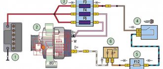
| 2 | 60 | Generator |
| 3 | 60 | Generator |
| 4 | 30 | Cooling system fan (versions without climate control or air conditioning) |
| 4 | 40 | Cooling fan |
| 5 | 50 | Electromechanical power steering |
| 6 | 40 | ABS |
For cars assembled in 2022, 2022
| No. on the diagram | Denomination, A | Protected Circuits |
| 1 | 60 | Generator |
| 2 | 60 | Generator |
| 3 | 30 | Cooling fan (in configurations without climate control or air conditioning) |
| 3 | 40 | Cooling fan |
| 4 | 40 | ABS/ESC |
| 5 | 25 | ABS/ESC |
| 6 | 50 | Electric power steering |
Removal and replacement instructions
Replacing and identifying an unusable element in both the first and second blocks occurs in approximately the same way, so let’s consider the replacement process using the example of the one installed to the left of the dashboard.
Diagram on the back of the cover
Preparation
Be sure to remember that before you carry out work on electrical equipment, it doesn’t matter whether the cigarette lighter or the fuel pump has failed, the first thing you need to do is turn off the power to the system. To do this, turn off the engine and remove the negative terminal of the battery.
This video shows how you can quickly solve a problem with blown fuses on a Lada Kalina.
- We find the location of the block, it’s not difficult - the designers placed it on the left side of the dashboard under the cover.
- Open the lid.
- Using the diagram and table, we establish the location of the protective element we need.
- The block contains tweezers, with the help of which we extract the required element.
- Let's examine it.
- We check with an ohmmeter or lamp.
- If the spiral is burnt out, install a new one of equal value.
- We connect the removed battery terminal.
- We start the car.
- Let's see whether our consumer has earned money or not.
- If everything is in order, then the work is finished. If the consumer does not work or the electrical fuse has blown again, then everything is more serious. It may be necessary to check the circuit or dismantle the consumer and check it.
Layout of relays and electrical fuses
Explanation of the diagram shown in the photo.
The request returned an empty result.
Work with the block, which contains the element protecting the fuel pump and other elements responsible for the operation of the engine, is carried out in a similar way.
The request returned an empty result.
The protective element designed for 15 amperes, responsible for the fuel pump of the Lada Kalina, is designated F2 in the photo. To remove it, you need tweezers. All other work is carried out in the same way as in the large compartment.
Recommendations for use
- If you are a responsible car owner, then be sure to carry with you a set of electrical fuses of various ratings. Perhaps they will help you out at some point.
- Under no circumstances should you install wires or bugs. This can lead not only to failure of the electrical consumer, but also to a fire.
- Replacement only with an element of the same value is acceptable.
- Before work, do not forget to turn off the power to the system.
Sorry, there are no surveys available at this time.
Removal and installation of VAZ (Lada) Kalina 1117 mounting blocks
Tool:
- Medium Phillips screwdriver
- Small tweezers
- Large tweezers
Note:
The relay and fuse mounting block is located in the instrument panel under the cover, to the left of the steering column. The cover contains a control unit for external lighting, instrument lighting and a regulator for the direction of headlight beams.
1. To access the mounting block, we pry the instrument panel cover by the lugs on the left and right sides.
2. We lower the lid.
3. The sockets for fuses and relays are marked on the body of the mounting block, and on the inside of the cover there is a diagram of the location and the purpose of the fuses and relays.
Basic information about the electrical circuit
The main fuse box in Kalina 2 is located to the left of the steering column and is covered with a plastic cover. On the inside there is a label with a printed diagram of the location of the parts.
Main unit located to the left of the steering column
Note that the “Lux” uses one set of relays, while in the “Normal/Standard” configurations it is slightly different. Relay “K5” is missing in both sets, and part “K6” may be missing in the “Standard” version. Fuse sets, in turn, may or may not contain element “F3” (automatic transmission fuse).
You can remove fuses only with special pliers, which you will find under the cover of the main unit.
Kalina mounting block (fuse box)
Electrical problems with the Lada Kalina occur just like with any other car. Finding out the causes of malfunctions is usually done by checking fuses and relays.
Mounting block Lada Kalina
The relay and fuse mounting block is located to the left of the steering column on the instrument panel.
Before replacing relays or fuses, be sure to disconnect the negative terminal of the battery.
Lada Kalina mounting block fuses
Fuse designation
(rated current. A) – Protected elements
F1(10) – Immobilizer, warning lights and arrow indicators of the instrument cluster, switch circuits and reverse lamps, direction indicator circuits F2 (30) – Electric window circuits F3 (10) – Hazard alarm circuits F4 (20) – Windshield wiper, rear window defroster switch circuit F5 (25) – Heater motor, electric power steering control unit, windshield washer F6 (20) – Horn F7 (10) – Instrument cluster LCD indicator, brake light switch and lamps, interior lighting F8 (20) – Rear window heating element F9 (5) – Side light bulbs in the right block headlight and right flashlight, glove compartment light bulb F10 (5) – Side light bulbs in the left block headlight and left flashlight, outside light indicator in the instrument cluster, license plate lamps F11 (7.5) – Chains of fog light lamps in the rear lights F12 (7.5) – Low beam lamp (right headlight), right headlight leveling motor gearbox F13 (7.5) – Low beam lamp (left headlight unit), light control gear motor of the left headlight unit F14 (10) – High beam lamp (right headlight unit), high beam headlight indicator in the instrument cluster F15 (10) – High beam lamp (left headlight) F16, 17 (10) – Fog lamps (optional) F18 (15) – Seat heating elements (optional) F19 (10) – ABS electrical circuits (optional) F20 (15) – Cigarette lighter heating element F21 (10) – Transmission reverse lock circuit F22 (15) – Security alarm control unit F23 – Reserve F24 – Reserve F25 – Reserve F26 (25) – ABS electrical circuits (optional) F27 (5) – Spare F28 (7.5 ) – Spare F29 (10) – Spare F30 (20) – Spare F31 (50) – Electric power steering
Note that in the previous article we looked at why the stove on a Priora does not work and how to repair it with your own hands.
Mounting block relay
Designation
– Name – Powered consumers
K1 (optional)
– Headlight washer relay – Headlight washer electric motor
K2
– Window lift relay – Window lift motors
KZ
– Starter relay – Starter traction relay
K4
– Additional relay – Switch and winding of the rear window heating relay, switch heater electric motor, windshield wiper and washer switch
K5
– Turn signal and hazard warning lamp relay – Turn signal and hazard warning lamps
K6
– Windshield wiper relay – Windshield wiper motor
K7
– High beam headlight relay – High beam lamp unit - headlights
K8
– Horn relay – Horn
K9 (optional)
– Fog lamp relay – Fog lamps
K10
– Rear window heating relay – Rear window heating element
K11 (optional)
– Seat heating relay – Seat heating elements
K12 (reserve)
–
Fuses, list and description
The electrical circuit of the Kalina-2 car can contain up to 38 fuses in total. The block installed under the hood contains 6 fuses designed for significant current. We, in turn, will consider the diagram of the main block:
All fuses in the electrical circuit of Kalina-2
- F1, 15A: ignition, injectors, power supply to the ECU and radiator fan relay;
- F2, 25A: power supply to the TsBKE unit and the front left door module;
- F3, 15A: electric drive of the automatic transmission, also power supply to the automatic transmission ECU;
- F4, 15A: power supply for airbag assembly;
- F5, 7.5A: speed sensor, brake pedal sensor, power supply to the instrument panel and ESD, ECM controllers, power supply to the automatic transmission selector, voltage on the windings of the unloading relay and the relay of the glass and seat heaters, power supply to the body electronics unit, washer switch;
- F6, 7.5A: power supply for automatic transmission electronics and reverse lamp relay;
- F7, 7.5A: voltage at the canister purge valve, at the phase sensor, mass air flow sensor, DC;
- F8, 25A: rear window heater and mirror heater circuit;
- F9, 5A: all “dimensions” on the right;
- F10, 5A: all “dimensions” on the left, license plate lights, keys;
- F11, 5A: rear fog lights;
- F12, 10A: low beam lamp, electric corrector for the right headlight;
- F13, 10A: low beam lamp, electric corrector for the left headlight;
- F14, 10A: high beam lamp on the right;
- F15, 10A: high beam lamp on the left;
- F16, 10A: “fog light” on the right;
- F17, 10A: “fog light” on the left;
- F18, 20A: seat heater circuit and cigarette lighter circuit;
- F19, 7.5A: ABS controller power supply;
- F20, 15A: signal;
- F21, 10A: fuel pump motor;
- F22, 15A: windshield and rear window washers, rear wiper;
- F23, 5A: power supply to the diagnostic connector, as well as to the instrument panel;
- F24, 7.5A: air conditioner motor-compressor clutch circuit, power supply to the air conditioner controller;
- F25, 7.5A: voltage at the brake pedal sensor;
- F26, 7.5A: ABS valve drives;
- F31, 30A: short-term switching on of high beams, power supply to the central bank, gear motor for front wipers;
- F32, 30A: heater fan circuit, power supply to the air conditioner controller.
Elements F27-F30 are reserve. There is no need to look for a separate fuse responsible for powering the radio - there is none. Therefore, you can immediately install a new radio without opening the cover of the main unit.
The high-current fuse box is located under the hood next to the battery. Its elements:
- FF1, 40A (30A): windshield defroster circuit;
- FF2, 60A: generator-battery line;
- FF3, 60A: generator-battery line;
- FF4, 40A: radiator fans;
- FF5, 50A: power supply of the EUR unit;
- FF6, 40A: ABS return pump power supply.
When replacing a fuse, remember the following. You cannot use a higher denomination than was provided. Otherwise, the risk of fire cannot be excluded.
Location of the main fuse block
The main fuse and relay block of the Lada Kalina is located under the left panel of the steering wheel, where the main light switch is located.
In order to gain access to the main fuse panel of the Lada Kalina, you need to do a number of manipulations:
- On the closing panel, on the left and right, there are grooves that need to be pulled alternately. Also below. This operation should be done carefully so as not to break the plastic fasteners.
Gently pull and remove from the grooves
Gained access to the fuse box
Thus, the fuses and relays of the main unit of the Lada Kalina, as well as the control board, are changed.
Location of additional fuse box
The additional fuse box is marked with an arrow in the photo.
The additional relay and fuse box for the Lada Kalina is located to the right of the front passenger's feet. It can be accessed by unscrewing the cover bolts and removing it. In order to dismantle this block, unscrew the 3 mounting bolts. The replacement process is carried out in the same way as with the main unit.
- fuel pump activation relay;
- cooling system electric fan fuse (50A);
- cooling system electric fan relay (low speed);
- main relay;
- cooling system fan relay high speed).
Circuit breakers
Relay and fuse mounting block
: F1-F31 – fuses; K1-K6 - large relay; K7-K12 - small size relay; 1 - small tweezers for removing small fuses and relays; 2 - large tweezers for removing large relays
If malfunctions occur related to the operation of electrical accessories on the Lada Kalina, do not rush to get into the mechanical part. Maybe the problem lies in the combustion of fuses. But not all motorists know where the Lada Kalina fuse box is located and their markings.
Diagram and marking of fuses and their replacement
If you turn over the cover of the Lada Kalina fuse box, you can see the markings and which fuse and relay are responsible for what. Also, it can be seen in the vehicle’s service and technical book.
Fuse box diagram
Let us indicate and decipher the fuse number, amperage and what it is responsible for:
F1 - (10) - Instruments: immobilizer control unit, hazard warning switch, instrument cluster. If, when starting the engine, the starter does not turn and the immobilizer icon flashes, then you need to pay attention to this fuse. F2 — (30) — Electric windows. Read more about why window lifts may not work here. F3 - (10) - Hazard warning switch F4 - (20) - Windshield wiper F5 - (25) - Heater, electric power steering control unit F6 - (20) - Horn F7 - (10) - Instrument cluster, interior lighting F8 - (20 ) — Heated rear window F9 — (5) — Side light (right side) F10 — (5) — Side light (left side) F11 — (7.5) — Immobilizer control unit F12 — (7.5) — Low beam (starboard side) F13 — (7.5) — Low beam (left side) F14 — (10) — High beam (starboard side) F15 — (10) — High beam (left side) F16.17 — (10) — Fog lights F18 — (15) — Heated seats F19 — (10) — ABS F20 — (15) — Cigarette lighter F21 — (10) — Reverse lock F22 — (15) — Electrical package control unit F31 — (50) — Control unit electric booster
Relay layout in the mounting block
Also, relays are installed on the fuse block. Let's give them a breakdown according to numbering:
K1 - headlight washer relay; K2 - power window circuit activation relay; KZ - starter activation relay; K4 - additional relay (ignition relay); K5 - relay for turning on direction indicators and hazard warning lights; KB - relay for turning on the windshield washer and wiper; K7 - headlight high beam relay; K8 - relay for turning on the sound signal; K9 - relay for turning on the front fog lights; K10 — relay for turning on the heated rear window; K11 — relay for turning on the front seat heating circuit; K12 - backup relay.
Replacing fuses and relays
Replacement of fuses and relays is carried out using special tweezers. They are in the photo below, marked with an arrow.
List of contact relays
If we open the main fuse box of Kalina 2, we will see a set of electrical relay housings. There are no other blocks containing relays in the car. We list the elements used in the “Lux” package (21927/21947):
- K1: radiator fan relay;
- K2: relay switching on door locks;
- K3: additional starter relay;
- K4: additional relay (switches current 50A);
- K6: wiper relay;
- K7: relay that turns on the high beam;
- K8: signal relay;
- K9: relay that turns on the low beam;
- K10: rear window heater relay;
- K11: main ignition relay;
- K12: relay turning on the fuel pump;
- K13: additional relay;
- K14: radiator fan relay 3;
- K15: windshield heater relay 1;
- K16: windshield heater relay 2;
- K17: relay that turns on the air conditioning compressor.
The pliers that you will find in the Kalina 2 fuse box will be of two types. “Large” ones are intended for dismantling relays K1-K6, as well as K13-K17.
You can compare the layout of elements in “Lux” and in “Norm/Standard”:
Location of the main fuse block
The main fuse and relay block of the Lada Kalina is located under the left panel of the steering wheel, where the main light switch is located.
In order to gain access to the main fuse panel of the Lada Kalina, you need to do a number of manipulations:
- On the closing panel, on the left and right, there are grooves that need to be pulled alternately. Also below. This operation should be done carefully so as not to break the plastic fasteners.
Gently pull and remove from the grooves
Gained access to the fuse box
Thus, the fuses and relays of the main unit of the Lada Kalina, as well as the control board, are changed.
Location of additional fuse box
The additional fuse box is marked with an arrow in the photo.
The additional relay and fuse box for the Lada Kalina is located to the right of the front passenger's feet. It can be accessed by unscrewing the cover bolts and removing it. In order to dismantle this block, unscrew the 3 mounting bolts. The replacement process is carried out in the same way as with the main unit.
- fuel pump activation relay;
- cooling system electric fan fuse (50A);
- cooling system electric fan relay (low speed);
- main relay;
- cooling system fan relay high speed).
Diagram and marking of fuses and their replacement
If you turn over the cover of the Lada Kalina fuse box, you can see the markings and which fuse and relay are responsible for what. Also, it can be seen in the vehicle’s service and technical book.
Fuse box diagram
Let us indicate and decipher the fuse number, amperage and what it is responsible for:
F1 - (10) - Instruments: immobilizer control unit, hazard warning switch, instrument cluster. If, when starting the engine, the starter does not turn and the immobilizer icon flashes, then you need to pay attention to this fuse. F2 — (30) — Electric windows. Read more about why window lifts may not work here. F3 - (10) - Hazard warning switch F4 - (20) - Windshield wiper F5 - (25) - Heater, electric power steering control unit F6 - (20) - Horn F7 - (10) - Instrument cluster, interior lighting F8 - (20 ) — Heated rear window F9 — (5) — Side light (right side) F10 — (5) — Side light (left side) F11 — (7.5) — Immobilizer control unit F12 — (7.5) — Low beam (starboard side) F13 — (7.5) — Low beam (left side) F14 — (10) — High beam (starboard side) F15 — (10) — High beam (left side) F16.17 — (10) — Fog lights F18 — (15) — Heated seats F19 — (10) — ABS F20 — (15) — Cigarette lighter F21 — (10) — Reverse lock F22 — (15) — Electrical package control unit F31 — (50) — Control unit electric booster
Relay layout in the mounting block
Also, relays are installed on the fuse block. Let's give them a breakdown according to numbering:
K1 - headlight washer relay; K2 - power window circuit activation relay; KZ - starter activation relay; K4 - additional relay (ignition relay); K5 - relay for turning on direction indicators and hazard warning lights; KB - relay for turning on the windshield washer and wiper; K7 - headlight high beam relay; K8 - relay for turning on the sound signal; K9 - relay for turning on the front fog lights; K10 — relay for turning on the heated rear window; K11 — relay for turning on the front seat heating circuit; K12 - backup relay.
Replacing fuses and relays
Replacement of fuses and relays is carried out using special tweezers. They are in the photo below, marked with an arrow.
Arrows indicate tweezers