Structurally, the wheel is the chassis of the vehicle; with the help of wheels, movement is carried out and vertical loads are transmitted. In addition, they soften mechanical impacts and vibrations at the moment of contact with the road surface, providing maneuverability and traction. The aerodynamics and controllability of vehicles depend on them.
So, we figured out what a wheel is. Now about its components. The wheel includes two structural parts: a tire and a disk.
Requirements for wheels
The following requirements apply to the wheels of cars and tractors:
- the geometric dimensions, shape and load-carrying capacity of the wheels must correspond to the design of the tires and their operating conditions;
- wheels must have a minimum mass and moment of inertia for a given design and durability;
- reliability of operation and installation of wheels must be ensured throughout the entire service life of the wheeled vehicle;
- the design of the wheels must ensure effective cooling of the brake mechanisms;
- the design of wheels for tubeless tires must ensure that the tires are sealed and their beads are securely seated on the rim flanges (to prevent the tire beads from sliding off the rim flanges, especially from the outside of the wheel, including when the air pressure in the tire decreases);
- the design of rims for adjustable pressure tires must exclude the possibility of the tire turning on the rim, both at nominal and at minimum permissible internal air pressure;
- the design of rims for promising tires for BAT must provide the possibility of mounting these tires on them and, if necessary, an internal deformation limiter, and therefore must be detachable and sealed;
- wheels must comply with international standards for basic geometric, landing, mounting dimensions and load characteristics in order to ensure their interchangeability;
- wheel runout, permissible imbalance, tolerances on dimensions and inclination of rim flanges and installation dimensions necessary for normal operation of tires must not exceed established standards;
- the design of the wheels must be adapted to perform installation and dismantling work carried out in case of tire damage;
- The coloring of the wheels should protect them from corrosion during the service life of the wheeled vehicle, and the appearance should be in harmony with the appearance of the wheeled vehicle.
Bus device
The tire is the second component of the wheel. It also has a rather complex design, since its task is to provide adhesion to the road surface, absorb and dampen vibrations from small irregularities, and retain weight. To perform its functions, the tire must be durable, but at the same time elastic. Note that the tire is a kind of shell that is filled with filler - air or special gases.
The tire consists of an elastic radial frame that gives the shape of the product, onto which a rubber layer, a breaker (power metal cord), a bandage of threads (nylon cord) and a tread are successively applied. Along the inner circumference, the radial frame forms the tire bead, into which a wire ring is installed for rigidity.
One of the bus schemes
The visible elements of the tire are the tread, which acts as the main working surface (it is in contact with the road surface) and the sidewall. The transition between these elements is called the shoulder.
To ensure traction on the road, the tread has a complex pattern, which is formed by ribs, blocks with grooves and lamellas.
Wheel classification
By type of wheeled vehicle:
- for passenger cars;
- for trucks;
- for buses, trolleybuses, trailers and semi-trailers;
- for tractors;
- for special wheeled vehicles.
In each group, wheels are distinguished by overall dimensions and load capacity (maximum radial load), and wheels for passenger cars are also distinguished by the maximum speed of the vehicle.
By type of tires used:
- wheels for tube tires;
- wheels for tubeless tires.
To ensure a tight fit of tubeless tires on wheel rims, increased requirements for cleanliness and roughness are imposed on the surfaces of the landing flanges and rim flanges.
By design:
- disk - for all wheeled vehicles;
- discless - for all wheeled vehicles, except passenger cars.
According to the rim design:
- non-separable deep (symmetrical or asymmetrical) rims with inclined flanges (5±1)0 or (15±1)0 (version with steep flanges): the first - for passenger car tires, the second - for radial tubeless tires of trucks, buses and trolleybuses, respectively;
- semi-deep collapsible rims with toroidal landing flanges (Figure 1), which have a mounting handle to ensure mounting and dismantling of the tire;
- flat rims, dismountable in longitudinal or transverse planes;
- split rims.
Figure 1. Semi-deep rim of a disc wheel : 1 – wheel disc; 2 – rim base
The main mounting dimensions of automobile wheels with dismountable rims are regulated by GOST 10409.
According to manufacturing technology:
- steel (profiled, stamped or made of hot-rolled steel);
- cast (from aluminum or magnesium alloys);
- forged (made of aluminum or magnesium alloys);
- from polymer composite materials.
Questions on the topic
Filter:AllOpenSolvedClosedWaiting for response
Which wheels to choose for a VAZ 2107? Answered by User answered 9 months ago • Tires and wheels
29 views 1 answer. 0 vote.
Will 225/50 R18 tires fit the Hyundai Sonata VII? Answered by User answered 9 months ago • Tires and wheels
28 views 1 answer. 0 vote.
What should be the tire pressure for Toyota Land Cruiser Prado 4? Answered by User answered 9 months ago • Tires and wheels
27 views 1 answer. 0 vote.
Can tires with different treads be used on the same car? Answered by User answered 9 months ago • Tires and wheels
28 views 1 answer. 0 vote.
What is the service life of tires? Answered by User answered 9 months ago • Tires and wheels
28 views 1 answer. 0 vote.
Why doesn't the tire pressure indicator work? Answered by User answered 9 months ago • Tires and wheels
30 views 1 answer. 0 vote.
What are the parameters of VAZ 2106 wheels? Answered by User answered 9 months ago • Tires and wheels
30 views 1 answer. 0 vote.
What size rims are on Volkswagen Passat? Answered by User answered 9 months ago • Tires and wheels
30 views 1 answer. 0 vote.
Can you tell me the wheel sizes for Nissan Qashqai? Answered by User answered 9 months ago • Tires and wheels
29 views 1 answer. 0 vote.
Can you tell me the size of the rims for the Jeep Liberty? Answered by User answered 9 months ago • Tires and wheels
36 views 1 answer. 0 vote.
Ask a Question
Wheel designs
3.1. Disc wheels
The production of disc wheels is currently predominant due to the simplicity of the design, the high accuracy of fastening the wheels to the hubs and the sophisticated technology of mass production.
The main characteristics of disc wheels are the width of the rim profile b, the landing diameter d and the angle of inclination of the landing flanges γpp.
For passenger cars, light trucks and buses of particularly small capacity, disc wheels with non-separable (asymmetrical or symmetrical) deep rims with an inclination angle of landing (conical) shelves γpp = 50 are used (Figure 2). Conical flanges improve the fit of the tire beads on the rim, increase the service life of the beads, and ensure reliable transmission of torque by the tire.
The non-separable deep rim consists of the following elements:
- flange 1, which are side supports for the tire beads;
- shelves 2, which are seats for the tire beads and transmit forces in the circumferential direction;
- stream 7, which is deep (deep rim) for mounting and dismantling the tire.
Figure 2. Asymmetrical rim of a disc wheel for passenger cars: 1 – flange; 2 – shelf; 3 – stream; b – rim profile width; d – bore diameter; f – stream depth; hз – edge height; 50 – angle of inclination of landing shelves
The asymmetrical rim has a rim offset to the outside of the wheel in order to leave more space for placing the brake mechanism.
To ensure a reliable fit of the beads of radial tubeless tires and to prevent them from sliding off the wheel rim flanges, which, when the car moves in a curved direction with partially reduced air pressure in at least one of the tires, can lead to loss of controllability, rim flanges for passenger cars are usually made with safe contours.
Figure 3. Symmetrical rim with a combined tackle : 1 – tackle from the inside of the rim; 2 – flat roll on the outside of the rim
The most widely used are: tackle (“Hump”, designated H) and flat tackle (“Flat-Hump”, designated FH). The underroll (Figure 3) is a rounded protrusion 1 located on the surface of one of the rim flanges, and the flat underroll is a protrusion 2 with a relatively sharp edge.
Figure 4. Double-sided rim
During the operation of radial tubeless tires, it was found that it is advisable to use safety contours on both sides of rims for passenger cars (Figure 4). This is a double-sided tackle (designated H2) or a combined tackle (designated CH), in which the outer flange of the rim is made with a flat tackle, and the inner flange with a tackle.
For trucks, buses and trolleybuses, when installing radial tubeless tires, disc wheels with non-separable rims with steep flanges having an inclination angle of 150 are used (Figure 5), and when installing tube tires, wheels with flat collapsible rims with oblique (conical) landing flanges are used, having an inclination angle of 50.
Collapsible rims can be two- or three-component (Figure 6).
With the same base 1, a three-component rim (Figure 6, a) consists of a bead ring 3, made in the form of a flange, and a split lock ring 2, and a two-component rim (Figure 6, b) consists of a split bead ring 3, which simultaneously serves as a lock ring.
Figure 5. Non-separable rim with steep flanges : 1 – edge; 2 – shelf; 3 – stream; b – rim profile width; d – bore diameter; 150 – angle of inclination of landing shelves
The disadvantages of a two-component rim include the reduced rigidity of the split bead ring, the presence of sharp edges at the cut site and a gap at the joint.
Figure 6. Wheel with a flat collapsible rim : a – three-component rim; b – two-component rim; 1 – rim base; 2 – lock ring; 3 – side ring; 4 – wheel disk; 5 – landing shelf; b – rim profile width; γpp – angle of inclination of landing shelves; d – bore diameter; D1 – diameter of mounting holes; D2 – diameter of the central hole
Wheels with collapsible rims with slanted flanges are the simplest in design and widely used, despite the fact that, with the same weight, they can take less load compared to non-separable wheels with rims with steep flanges. They also leave less room for brake cooling and generate more heat.
For cars equipped with tires with adjustable air pressure, disc wheels with a split rim and an internal spacer ring are used, which come in regular and wide profiles, as well as wheels with a semi-deep rim with toroidal landing shelves.
A disc wheel with a split rim (Figure 7) consists of a disk 4 and a rim 2 welded to it, a bead ring 3 and a seat ring 5, and a spacer ring 1. When mounting the tire, the disk and bead ring are connected with bolts 6 and nuts 9. A split spacer ring with a special The hinge lock presses the tire beads to the edges of the rim.
Figure 7. Disc wheel with a split rim and a spacer ring : 1 – spacer ring; 2 – wheel rim; 3 – side ring; 4 – wheel disk; 5 – landing ring; 6 – bead ring fastening bolt; 7 – tire; 8 – camera; 9 – bead ring fastening nut
In modern military vehicles equipped with a tire pressure regulation system, the transmission of torque from the tire to the rim at the minimum permissible internal air pressure in the tire is ensured by a tight fit of the tire beads on the conical flanges of the rim.
In this case, the spacer ring keeps the tire beads from accidentally sliding off the conical flanges of the rim.
Disc wheel with a semi-deep rim with toroidal landing flanges (the figure also consists of a disk 10 and a rim 1 welded to it. Both bead rings 2 are removable, and the outer one is fixed with a split lock ring 7. The limiter 8 ensures the fixation of the outer and lock rings in a strictly defined The protective cover of the air supply hose is simultaneously fixed in the limiter after installing the wheel on the hub.
The toroidal surfaces of the rim flanges ensure a constant tension between the tire and the rim, a reliable fit of the tire beads on the rim flanges without a spacer ring for a given range of changes in air pressure in the tire.
A wheel with a rim of this design, if the valve is sealed, allows the installation of tubeless tires with adjustable air pressure.
Figure 8. Disc wheel with a semi-deep rim with toroidal landing shelves: 1 – wheel rim; 2 – side rings; 3 – rim tape; 4 – camera; 5 – valve groove seal; 6 – tire; 7 – lock ring; 8 – limiter; 9 – chamber valve; 10 – wheel disk; 11 – balancing weight; 12 – load securing bracket
For tires of heavy-duty trucks and buses of the corresponding classes, disc wheels with flat collapsible rims with two removable flanges are used (Figure 9).
For tires of general-purpose tractors and universal row-crop tractors, disc wheels are used in design similar to the wheels of trucks.
General-purpose tractors have all wheels of the same size, and universal row-crop tractors have smaller front steered wheels compared to the rear drive wheels, which is done to make turning easier and reduce the turning radius, as well as due to the need to change the track of the drive wheels to perform agricultural work. works .
Figure 9. Wide-profile tire wheel : 1 – rim base; 2 – edge; 3 – seat ring; 4 – lock ring; 5 – wheel disk
Changing the track shown in Figure 2.10 is possible for tractors in which the disks 1 of the rear drive wheels are bolted to the flanges 3 of the drive shafts and to the brackets 2 of the wheel rims. By swapping the rear wheel assembly with rims, you can change the track by one amount, and by rearranging the wheel rims on the rim brackets, by another amount.
Figure 10. Changing the track of the tractor drive wheels by rearranging the rim relative to the disk : 1 – rear drive wheel disk; 2 – wheel rim bracket; 3 – wheel drive shaft flange
A stepwise change in the track of the rear drive wheels is provided for in the design of the MTZ-80 tractor (Figure 11). The wheel hub is secured to the axle shaft 1 using a key and liner 3. A worm 2 is mounted in the liner, the turns of which fit into the slots of the axle shaft. By turning the worm, you can move the drive wheel on the axle shaft and obtain the track required for work. To do this, you need to jack up the wheel and loosen the bolts securing the liner to the wheel hub.
To obtain the largest track, the disks of the tractor's drive wheels must be positioned with their convex part inward.
Figure 11. Rear drive wheel of the MTZ-80 tractor: 1 – axle shaft; 2 – worm; 3 – liner; 4 – additional load
To increase the adhesion of the driving wheels of the tractor with the supporting surface when performing agricultural work, additional weights 4 are hung on the disks, which are removed when using the tractor for transport work.
Disc wheels have the following disadvantages:
- limited possibility of further increasing the load capacity of vehicles without increasing the size and weight of the wheels due to their low specific load capacity (the ratio of the vertical load on the wheel to the weight of the wheel), not exceeding 560...700 N/kg;
- insufficient durability of wheels, determined mainly by the durability of disks;
- poor cooling of rims, tires and brakes;
- high complexity of manufacturing and servicing wheels during vehicle operation, caused by a large range of fastening parts and the increased weight of wheels.
The highest specific load capacity, which exceeds by approximately 30...35% the specific load capacity of wheels with collapsible rims with oblique flanges, are wheels with wide non-separable rims with steep flanges, on which radial tubeless tires for trucks with a H/B ratio = 0.7... are mounted. 0.8 (Figure 12).
Figure 12. Wheel with a wide one-piece rim
To reduce weight, disc wheels are provided with holes that simultaneously serve for ease of installation and dismantling and for ventilation of the brake mechanisms.
3.2. Discless wheels
Discless wheels are used on trucks with a rated wheel load exceeding 20 kN and general purpose tractors with a 4K4b wheel arrangement. They consist of a rim and a spoke hub. The rims on the hubs are secured with clamps, bolts or studs and nuts that have only right-hand threads.
There are two fundamentally different designs of discless wheels: with longitudinally collapsible and transversely collapsible rims. Fastening of discless wheels to hubs is carried out according to uniform schemes.
Currently, discless wheels with longitudinally collapsible rims (Figure 13) have found quite wide application in the automotive industry. However, they have disadvantages that hinder their further spread:
- relatively low accuracy and increased labor intensity of installing wheels on hubs;
- insufficient reliability of fastening, which in operation leads to rotation of the wheels on the hubs and, as a consequence, cutting off the rotation limiters and breaking the chamber valves;
- strict requirements for the production of rims in order to ensure minimal deviations of seating dimensions, ovality, axial and radial runout values.
Figure 13. Discless wheels with longitudinally collapsible rims : a – fastening of dual wheels; b – fastening of a single wheel; 1 – rim; 2 – clamp; 3 – hub; 4 – spacer ring; A – conical surface
Discless wheels with transversely collapsible rims (Figure 14) are considered more promising [6, 10, 13]. The rim usually consists of three segments 1 of equal size, closed when assembled into a single ring, and has an annular internal protrusion with a conical belt facing the wheel hub 2. The hub also has a similar conical belt. Thus, the centering of the rim on the hub is carried out by these conical surfaces. The rim is fastened to the hub using clamps 4, tightened with nuts 3 on studs 5. This design makes it possible to practically eliminate the above-mentioned disadvantages of both disc and discless wheels with longitudinally collapsible rims.
Wheels with transversely collapsible rims have the following disadvantages compared to wheels with longitudinally collapsible rims:
- metal consumption increased by approximately 18%;
- the difficulty of ensuring rim tightness when using tubeless tires;
- difficulty in processing the landing and butting surfaces of the sectors.
Figure 14. Discless wheel with a transversely collapsible rim : 1 – rim segments; 2 – spoked wheel hub; 3 – nut; 4 – clamp; 5 – hairpin
For general purpose tractors, the discless design of the drive wheels makes it possible to reduce the overall width while maintaining ground clearance, since the final drives with discless wheels are located inside the wheel rims.
3.3. Wheels for special wheeled vehicles
Wheels for special wheeled vehicles include wheels for arched tires, pneumatic rollers and heavy-duty wheeled vehicles.
For arched tires, special wheels with a soft rubber seal are used (Figure 15). They consist of a special rim - a spherical shell 1 - with internal bead rings 5 and disk 2 welded to it, removable bead rings 4, rubber sealing and compensating rings 3 and fastening bolts and nuts.
Sealing is accomplished by clamping the tire beads between removable bead, rubber and inner bead rings. The diameter of the sealing-compensating ring, as well as its rigidity, is selected from the condition of the required pressing force on the tire bead at its minimum permissible thickness. In this case, the tire bead has no residual deformation. This sealing method is most appropriate for wheels of arched and wide-profile tubeless truck tires operating in difficult road conditions, as well as for wheels of pneumatic rollers.
Figure 15. Disc wheel for an arched tire : 1 – wheel rim; 2 – disk; 3 – rubber ring; 4 – side ring; 5 – inner side ring
The rims of pneumatic rollers are similar in principle to securing the tire beads to the rims of arched tires.
Figure 16. Wheel for a large tire : 1 – rim; 2 – edge; 3 – seat ring; 4 – lock ring
Wheels for heavy-duty wheeled vehicles are mainly discless (Figure 16). They consist of a rim base 1, made by welding, a seat ring 3, removable flanges 2 and a removable locking split ring 4. The installation and dismantling of large tires on rims is carried out using special equipment.
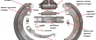
Rear hub replacement tools
To dismantle the hub you will need the following tools:
- Set of socket heads with extension.
- Pliers (pliers) for removing the locking ring.
- A spanner wrench for unscrewing the brake drum guide pins.
- A block of wood to prevent metal from hitting metal.
- Percussion instrument (hammer, cleaver, half sledgehammer).
- Mount.
- Chisel.
How to replace the hub:
- Loosen the wheel nuts.
- Raise the car with a jack. Place supports for belaying. Place anti-recoil devices (shoes).
- Remove the decorative cap (center of the wheel).
- Unscrew the wheel nuts.
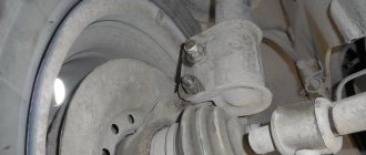
- Remove the brake drum from the hub or remove the disc brake caliper.
- Unscrew the bolts securing the hub to the bracket. The bolt is unscrewed through a special hole in the hub itself. To gain access, you need to rotate the flange until the holes line up with the bolts. These nuts are tightened with a large torque, so unscrewing them is not so easy.
- Unscrew the caliper mounting bolts, steering knuckle mounting bolts and brake pad guides.
- Pull out the hub. The rear hub is removed from the bearing. You need a special puller to press the hub off the bearing.
Wheel materials and technology
Large-scale production wheels are made mainly by cold stamping from sheet steel and consist of a rim and a disc connected to it by welding. Wheels made of aluminum or magnesium alloys are manufactured using low-pressure die casting or hot die casting (forging).
The main advantages of wheels made of steel sheet are low cost and the possibility of restoration (straightening) after deformation (crushing, bending). Their disadvantages include low corrosion resistance, relatively large weight (for example, the weight of a passenger car wheel of size 51/2Jx13 is on average 6.5 kg) and inexpressive design.
Cast wheels made of aluminum or magnesium alloys (Figure 17) have high corrosion resistance and a very expressive design. Compared to wheels made of steel sheet of the same size, they have less weight (by 15 and 30%, respectively) and greater strength. As a result, a car with such wheels has a reduced unsprung weight, which has a beneficial effect on the performance of the suspension. With the same efficiency of shock absorbers, better contact of the vehicle wheels with the supporting surface is ensured. The lower moment of inertia of cast wheels provides the car with better dynamic and braking properties. In addition, light alloys have good thermal conductivity, which, together with large holes in the discs, contributes to more efficient cooling of the brake discs and calipers.
Figure 17. Cast wheels
The main disadvantages of cast wheels are:
- excessively thick walls;
- fragility due to the presence of hidden casting pores and cavities;
- difficulty (often impossibility) of recovery;
- high price.
Forged wheels are stronger than cast ones, their wall thickness is 1.5...1.8 times less, and their weight is 15...22% lower. Forged wheels do not crack (do not split) and are not subject to collapse. Their main disadvantage is their higher cost compared to cast wheels.
A common disadvantage of forged and cast wheels, which manifests itself when operating a car on broken roads, is their high rigidity. These wheels (unlike conventional steel wheels) have virtually no flexibility, as a result of which direct impacts to them are transmitted directly to the suspension and chassis of the car and significantly reduce their service life.
Wheels made of magnesium alloys are lighter and stronger than those made of aluminum. However, they have not found widespread use due to their low corrosion resistance. To protect such wheels from environmental influences, they are coated with protective varnishes or paints, which leads to a further increase in their cost.
Materials for polymer composite wheels are reinforced plastics based on glass, carbon or hybrid fibers and thermosetting (polyester, epoxy, epoxyphenol) or thermoplastic binders (polycarbonate, polyamide). Glass-filled thermoplastics are processed into products using the high-performance injection molding method, and fiberglass plastics based on polyester and phenolic resins, which are the cheapest materials, are processed using the pressing method.
Figure 18 shows examples of fiberglass wheel designs for trucks (Figure 18, a, wheel with a split rim) and passenger cars (Figure 18, b, non-separable wheel) cars, made by pressing from prepreg and injection molding from glass-filled polycarbonate, respectively.
Figure 19 shows the design of a wheel for a pressure-controlled tire, where the rim base is made by winding glass fabric impregnated with an epoxy resin binder. Table 1 shows methods for manufacturing wheels from polymer composites
materials, which depend on the volume of production, the material used and the design of the wheel.
Figure 18. Fiberglass wheels
Table 1. Methods for manufacturing wheels from polymer composite materials
| Material | Volume of production | Design features | Manufacturing method |
| Laminated fiberglass based cold polyester binder curing | Experienced, single | Unlimited | Contact molding |
| Laminated fiberglass based hot polyester binder curing | Small-scale | Split wheel with elements constant or variable sections suitable for direct pressing | Pressing |
| Prepreg or dispensed press material | Medium production | Split wheel with elements constant cross-section, suitable for direct pressing | Pressing |
| Glass-filled thermoplastic | Large-scale | One-piece wheel simple configuration and small size | Stamping |
| Glass-filled thermoplastic | Large-scale | One-piece wheel of complex configuration | Injection molding |
| Laminated fiberglass based hot epoxy resin curing | Serial | Split wheel rim | Winding |
The use of polymer composite materials significantly expands the capabilities of designers in the development of non-traditional wheel designs. For example, by making the disk part of the wheel spherical or elliptical with a radial arrangement of reinforcing fibers, it is fundamentally possible to create wheels that increase the smoothness of the car, which will function as shock absorbers for the suspension system and low-profile tires.
Figure 19. Design of a wheel with a rim base made of polymer composite material : 1 – rim base; 2 – side rings; 3 – end ring; 4 – flange ring; 5 – pin-bolt connections
Purpose, functions
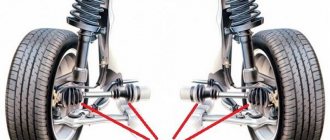
In general, car wheels are divided into three categories, depending on the function they perform - driving, steering, supporting. The drive wheels are rotated and, through contact with the road, they cause the car to move. But in the process of moving a car, it is necessary to change the direction of movement, maneuver, and the steered wheels are responsible for this.
Trucks are designed to transport goods and to reduce the load on the drive and steered wheels; support wheels have been added to the design of the chassis. They do not set the car in motion, do not participate in maneuvering, their task is to take part of the load “on themselves”.
Passenger cars use 4 wheels, but in trucks their number can reach 12, and in special equipment - up to 24. It is noteworthy that on trucks the wheels are usually divided into categories - some of them are driving, the second are steered, and the rest are supporting.
Drive cars
As for passenger vehicles, the types of car wheels they use can be divided according to their intended purpose or be combined. For example, in rear-wheel drive models, the wheels installed on the rear axle are driven, and those on the front axle are steered. But in front-wheel drive versions, the wheels of the front axle are both driven and steered, while the rear wheels perform only a supporting function.
Wheel designations
The wheel designations established by the standards of various countries are applied to one of the sides of the wheel disk or the rim of a discless wheel and include:
- manufacturer's trademark;
- wheel number;
- rim dimensions and shelf design;
- standard to which the wheel dimensions correspond (DIN, GOST);
- date of manufacture (month or week and year of manufacture).
Dimensions of disc wheel rims include profile width and rim mounting diameter in inches or millimeters, separated by an “x” for non-separable deep rims (5Jx13) and rims with steep flanges (9.00x19.5) and a “-” sign for collapsible semi-deep (228G) -508) and flat rims (10.0-20; 330-533). The letters between the numbers indicate different shapes of the edges and different designs of the shelves and stream (information can be found in the reference literature).
If there is a safety contour on the flanges of rims for passenger cars, this contour is indicated in the designation after the rim dimensions (for example, 5Jx13H2, where H2 means double-sided rolling). The wheel offset (ET) is also indicated in millimeters, for example, ET30. Thus, the complete characteristics of disc wheels for passenger cars are shown in Figure 20.
Figure 20. Characteristics of a passenger car disc wheel
The location of the deep wheel rim groove (symmetrical or asymmetrical) is visible on the wheel and is not marked.
The correspondence between passenger car tire sizes and wheel rim profile sizes is given in Table 2.
Table 2. Correspondence of tire sizes to wheel rim profile sizes
Tire designation | 135/80R12 | 155/80R13 | 155/65R13 145/80R13 | 175/70R13 | 185/65R13 175/60R13 |
Wheel rim designation | 4.00V | 4½J | 5J | 5J, 5½J | 5½J |
Tire designation | 155/65R14 | 185/70R14 165/65R14 | 175/65R14 | 185/55R14 165/55R14 | 205/70R14 |
Wheel rim designation | 4.5J, 5J, 5½J | 5J, 5½J | 5J, 5½J, 6J | 6J | 6J, 6½J |
Tire designation | 175/65R15 175/60R15 | 185/65R15 175/50R15 | 205/65R15 195/55R15 | 215/75R15 205/60R15 195/45R15 | 235/75R15 225/75R15 |
Wheel rim designation | 5½J, 6J | 6J | 6J, 6½J | 6½J, 7J | 7J |
Tire designation | 175/80R16 | 205/60R16 | 235/60R16 225/65R16 205/50R16 | 245/70R16 225/55R16 | 265/70R16 255/65R16 245/50R16 |
Wheel rim designation | 5½J, 6J | 6J, 6½J, 7J | 6½J, 7J | 7J, 7½J | 8J |
Tire designation | 235/60R17 215/50R17 205/50R17 | 225/50R17 215/35R17 | 245/60R17 235/45R17 | 255/65R17 245/50R17 | 285/70R17 265/65R17 |
Wheel rim designation | 7J | 7J, 7½J | 7½J, 8J | 8J | 8J, 8½J |
Tire designation | 235/60R18 | 255/55R18 245/45R18 | 265/65R18 235/40R18 | 255/45R18 245/40R18 | 285/55R18 275/40R18 |
Wheel rim designation | 7½J | 7½J, 8J | 8J | 8J, 8½J | 8½J, 9J |
Tire designation | 225/55R19 | 235/55R19 225/35R19 | 255/45R19 245/35R19 235/35R19 | 255/30R19 | 265/50R19 |
Wheel rim designation | 7½J | 8J | 8J, 8½J | 8½J, 9J | 9J, 9½J |
Tire designation | 255/50R20 225/30R20 | 245/40R20 | 265/50R20 | 275/40R20 | 305/50R20 285/50R20 |
Wheel rim designation | 8J | 8J, 8½J | 8½J, 9J | 8½J, 9J, 9½J | 9J, 10J |
Tire designation | 245/40R22 | 265/40R22 | 295/40R22 285/45R22 | 305/40R22 | 305/30R26 |
Wheel rim designation | 8½J | 9½J | 9½J, 10J, | 10J, 10½J | 10J |