Manual transmission synchronizers provide smooth gear transitions, making driving more enjoyable. However, this device has a complex design and, if it breaks down, requires expensive repairs. Therefore, car owners must understand how the synchronizer works in the gearbox in order to prolong its performance.
Purpose of the synchronizer
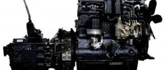
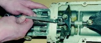
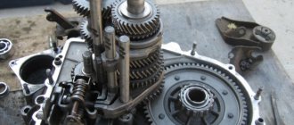
General view of the synchronizer All gears of modern passenger car gearboxes, including reverse gear, are equipped with a synchronizer.
Its purpose is as follows: to ensure equalization of the rotation speed of the shaft and gear, which is a prerequisite for shock-free gear shifting. The synchronizer not only ensures smooth gear shifting, but also helps reduce noise levels. Thanks to the element, the degree of physical wear of the mechanical parts of the box is reduced, which, in turn, affects the service life of the entire gearbox.
In addition, the synchronizer simplified the principle of gear shifting, making it more convenient for the driver. Before the advent of this mechanism, gear shifting occurred by double squeezing the clutch and shifting the gearbox to neutral.
Main types
There are different types of synchronizers: some use locking rings, others use locking pins. These units differ in the way the clutch is locked until the angular velocities of the shaft and gear are matched, which affects their design and operating principle.
With locking rings
Such devices are used in passenger car gearboxes. The basis of their mechanism is a hub with internal splines, with the help of which the part is held on the secondary shaft.
With locking fingers
The basis of the design of such a device is a carriage - a hub with a flange mount. By means of a spline connection, it is held on the driven shaft and moves freely along it. On the outer surface of the carriage there are ring teeth designed to engage the gears.
There are 6 through holes made on the flange: locking pins pass through 3 of them, and crackers (split fasteners) pass through the remaining 3. The fingers rigidly fasten the cone rings on the sides of the hub.
When the gear is engaged, the carriage moves along the shaft using a fork. At some point, the cone ring comes into contact with the gear and rotates due to frictional forces, driving the carriage and holding it in the groove of the locking pins. When matching angular velocities, inertia tends to zero, as a result of which the hub is centered relative to the locking pins and moves freely on the shaft. During movement, the crackers are compressed and the part comes into contact with the gear. The torque from the gear ring is transmitted through the carriage to the driven shaft and then to the clutch.
Operating principle of the gearbox synchronizer
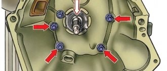
Scheme of operation of the synchronizer When the clutch is turned off, it occupies the middle position, and the gears rotate freely on the shaft. In this case, no torque transmission occurs. In the process of selecting a gear, the fork moves the clutch towards the gear, and the clutch, in turn, moves the locking ring. The ring is pressed against the gear cone and rotates, making further advancement of the clutch impossible.
GEARBOX SYNCHRONIZER IN ACTION
When the gearbox selector is in the neutral position, each synchronizer clutch is located in the middle position. With this arrangement, power transmission through them is completely eliminated. In this case, the gears located on the driven shaft do not have any obstacles to rotation.
As soon as we change gear, the clutch immediately moves with the help of the gearbox fork to a position similar to that occupied by the gears, following them. The shift of the clutch is accompanied by a change in the position of the cotters, which affects the locking ring, which as a result lies close to the gear cone. Due to the friction force created at this time between the surfaces, the ring rotates until the crackers are aligned with the grooves. The stopping of the ring during this period of time occurs precisely because of turning.
This is exactly how, in its final position, this unit works according to its purpose - it does not allow subsequent movement of the engagement clutch along the path of the shaft axis. This happens because all the ends of the splines, located along the entire perimeter of the ring, without exception, stand opposite the same parts of the clutch mechanism.
cross-sectional diagram of a synchronizer
Subsequently, the speeds of the driven shaft and gears are synchronized using the friction force generated by the interaction of the surfaces. Next, when the gear alignment process is completed, the locking ring begins to rotate in the opposite direction.
Thus, the clutch, which was previously blocked and limited in its trajectory, begins to function, and its splines engage with the ring gear, having free play. Next, the gears are connected to the gearbox output shaft.
The entire process described may seem complicated not only to a novice car enthusiast, but even to an experienced mechanic who is well versed in the structure of the transmission. However, despite the versatility of the synchronizer, the switching process in practice occurs almost at lightning speed and takes no more than a few fractions of a second.
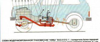
Operating principle and design of a three-shaft manual transmission
The fundamental principle of the operation of a manual transmission is the gear interaction of gears, which are enveloped in transmission fluid located in the gearbox housing.
This manual transmission includes:
- driving and driven shafts;
- intermediate and additional shafts;
- frame;
- synchronizers;
- gear sets;
- gear switching mechanism with locks and locking mechanisms;
- gear shift lever.
Bearings located in the housing ensure rotation of the shafts. Each shaft has a set of gears with a different number of teeth.
The drive shaft is connected to the engine via a clutch basket, the driven shaft is connected to the cardan shaft, and the intermediate shaft transmits torque to the secondary shaft.
There is a drive gear on the input shaft, which spins the intermediate gear with a firmly fixed set of gears located on it. The driven shaft has its own set of gears moving along splines.
Between the gears of the secondary shaft there are synchronizer clutches, which equalize the angular speeds of the gears with the revolutions of the shaft itself. The synchronizers are firmly attached to the shafts and move longitudinally along splines. On modern manual transmissions, such clutches are located at each stage.
–
CONDITION 1
RESULTS ASSURANCE ASSURANCE ведомого вала. RESULTS ROOM ROOM ROOM ROOM ROOM SÑÑеÑÑеÑен SÑÑеÑÑей "" â
RESULTS RESULTS 3 – RESULTS otp. RESULTS ROOM ROOM ROOM ROOM ROOM SYSTEM 3 – “Right” â
Synchronizer design
The synchronizer consists of the following elements:
- hub with breadcrumbs;
- engagement clutch;
- locking rings;
- gear with friction cone.
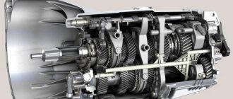
Synchronizer device
The basis of the unit is a hub having internal and external splines. With the help of the former, it is connected to the gearbox shaft, moving along it in different directions. Using external splines, the hub is connected to the coupling.
GEARBOX SYNCHRONIZER DEVICE
Each gear of a modern mechanical and robotic transmission is equipped with synchronizers. The gear responsible for moving the vehicle in reverse is no exception. The basis that allows the mechanism to work is the friction force at the moment the current speed is equalized. The quantitative value of this value increases in direct proportion to the increase in the difference in the rotation frequencies of the gears and shaft themselves.
This condition can only be met when the area of both surfaces that are subject to contact during interaction increases. In practice, this problem is solved by adding several friction rings to the gearbox device. The components of the synchronizer device are:
- engagement clutch - serves as a connecting link between the shaft and gears, ensuring a reliable connection of the gearbox parts. The coupling is located on top of the hub as an attachment. A special feature of the coupling structure is the presence of internal splines with grooves to match the shape of the rings. In the grooves there are protrusions of the crackers. As for the external structure of the coupling, it has a connection with the transmission fork;
- a hub with spring-loaded nuts is the structural basis of the mechanism. Equipped with slots both inside and outside. The former allow you to establish a connection with the coupling, the latter act as a connecting link with the secondary shaft of the transmission, due to which the hub has the ability to move along the axis in any trajectory. If you look at the structure of the hub, you will notice how 3 grooves are integrated along its circumference at the same distance from each other, and in each of them there are spring-loaded crackers. The function of the latter is to interact with the locking ring by pressing. Thus, when synchronizing and turning on one of the speeds, the clutch is forced to lock;
- locking ring - a device responsible for the timeliness and correct synchronization. Its task is to prevent premature closure of the synchronizer clutch until the rotation speeds of the gears and shaft take on the same values. The internal surface of the locking ring allows it to effectively interact with the friction cone of the gear, and with the help of external splines the operation of the clutch is blocked. The design features of such rings in different gearboxes have their own design features. For example, in some variations there are grooves in the hub, and protrusions in the locking ring itself;
- friction cone gears.
To optimize the effort expended by the mechanism to change the current gear and, accordingly, increase the contact surface, engineers went further and developed synchronizers with several cones, which are equipped with additional locking rings.
If the gearbox synchronizer has 3 cones, then there will be the same number of friction surfaces. Their number will depend on the design features of the gearbox itself and the vehicle on which it is installed.
Synchronized gearboxes, what does this mean?
Nowadays, virtually all mechanical and robotic boxes are synchronized. To turn on the speed in boxes of this type, a necessary condition is to equalize the rotation speed of the gear and shaft. Synchronization is provided by a device called a synchronizer. In addition to smooth gear shifting, it can reduce noise when changing gears, reduce wear on the mechanical connection and thereby increase the service life of the gearbox. All transmission gears of a passenger vehicle, including reverse gear, are equipped with synchronizers.
Practice driving a car with a synchronized manual transmission
When driving a non-synchronized gearbox (in particular, on antique domestic cars of pre-war production), the driver is forced to use special gear shifting techniques to prevent engine failure and rapid wear of gearbox gears. Quickly changing gears from low to high on such cars is impossible due to the difference in the rotation speed of the secondary shaft gear and the clutch. To equalize the rotation speed, the driver is forced to use the technique of double-clutch release. It consists in the fact that the driver depresses the clutch, moves the gearshift lever to the neutral position, releases the clutch for a short time, then depresses the pedal again and engages the highest gear. At the moment the “neutral” is selected, the rotation speeds of the gears are equalized. Gear shifts occur without grinding or large shock loads on the gear teeth. To switch from high to low gear on cars with a non-synchronized gearbox, use the technique of double squeezing the clutch “with re-throwing”. After squeezing the clutch, the driver moves the gearshift lever to neutral, presses the gas pedal, then depresses the clutch again and engages low gear. Due to the spinning of the intermediate shaft gears, the rotation speed of the connected gear and the engagement clutch is equalized. The transmission, again, engages without grinding. The same gear shifting techniques are still used in construction and specialized machines (graders, tractors, low-speed tractors) with multi-stage manual transmissions, in which the use of synchronizers is impossible. In synchronized gearboxes, the described techniques are meaningless, since the engagement of gears with a large difference in rotation speeds will be blocked by the synchronizer. A large shock load on the teeth of the gears (ring gears) will not occur, since the gears simply will not engage until the rotation speed is equalized. In fact, the manual transmission synchronizer performs the functions of a semi-automatic gear shift, eliminating the very possibility of rough engagement of the gearbox gears, which can damage the gearbox mechanism. On cars with partially synchronized manual transmissions (for example, GAZ-21), drivers, to switch from second to first gear, which did not have a synchronizer, moved the steering column shift lever for a short time to the third gear position, and then quickly to the first gear position. This made it possible to partially synchronize the rotation of the shift clutch and the first gear gear with the only synchronizer of the gearbox of this car.The same technique was used to engage reverse gear.
Manual transmission device
A manual transmission consists of a clutch basket and the gearbox itself.
The power unit includes:
- crankcase (housing);
- primary, secondary and intermediate shafts;
- stage selection device;
- driven and driving sets of gears;
- synchronizers;
- bearings, couplings and seals.
All these components are located in the housing and interacting with each other transmit torque.
Clutch
The clutch is an integral component of a manual transmission, which disconnects the engine and gearbox at the moment of gear shifting without consequences for the units. To exaggerate, the clutch turns off the torque, while both the engine and the wheels of the car spin at idle.
The clutch is designed to neatly connect the motor and wheels. It consists of two disks, one of which is connected to the car’s motor, the second to the wheels of the vehicle. The transmission of torque is carried out through the input shaft of the transmission.
Synchronizer resource
In case of any malfunctions related to gear shifting, it is first necessary to rule out problems with the clutch and only then check the synchronizer.
You can independently identify a unit malfunction using the following signs:
- Noise when the gearbox is running. This may indicate that the locking ring is bent or that the cone is worn out.
- Spontaneous gear shutdown. This problem can be associated with the clutch, or with the fact that the gear has outlived its service life.
- Difficulty engaging the gear. This directly indicates that the synchronizer has become unusable.
Repairing a synchronizer is a very labor-intensive process. It is better to simply replace the worn mechanism with a new one.
Compliance with the following rules will help extend the service life of the synchronizer and gearbox as a whole:
- Avoid aggressive driving style and sudden starts.
- Select the correct speed and gear.
- Carry out gearbox maintenance in a timely manner.
- Timely change the oil intended specifically for this type of gearbox.
- Fully depress the clutch before changing gears.
Signs of breakdown/wear of the synchronizer or its individual parts
Transmission problems often look the same, although they have different causes. Please note that if the owner is not familiar with the structure of individual components of the car, unscrupulous craftsmen can take advantage of this. For example, instead of repairing or replacing the gearbox synchronizer, they may offer to replace or overhaul the entire gearbox.
To avoid unreasonable expenses, it is worth knowing what signs indicate possible malfunctions of the gearbox synchronizers. Synchronizer problems may be indicated by:
- noise when changing gears;
- you have to make a lot of effort to engage the gear;
- the transmission does not engage or does not engage clearly;
- spontaneous transmission shutdown; We also recommend reading the article about how a manual transmission works and works. From this article you will learn about the main elements that make up a manual transmission, as well as the principle by which this type of box operates.
In order to check the synchronizers, you will have to disassemble the gearbox and try to move them by hand. The coupling should move easily along the splines. If you have to make an effort or you can’t move it, then you need to remove the synchronizer and disassemble it to inspect the surfaces of the parts for damage. If necessary, worn or damaged elements must be replaced. A complete replacement of the synchronizer can also be carried out immediately.
Synchronizer malfunctions and ways to eliminate them
If any difficulties arise with shifting gears, most car owners who have at least basic knowledge about the structure and principle of operation of the gearbox believe that the synchronizer is to blame. This often turns out to be true, although you should first rule out clutch malfunctions, which also quite often cause problems in the operation of a manual transmission when the system operates with jamming, a certain delay, and so on.
If the check does not reveal any violations, you can independently suspect problems with the synchronizer based on the following symptoms:
- When the gears switch off spontaneously, first of all, you need to pay attention to the release clutch and gears, which may be worn out.
- If, when switching gears, a noise appears, the identification of which is impossible and which was previously uncharacteristic, this may indicate that the locking ring is bent or that its conical part is worn out.
- Difficult gear shifting, when it is necessary to make a lot of effort and make several attempts, is virtually guaranteed to indicate a failed synchronizer.
It should be said right away that repairing this device is extremely labor-intensive and virtually impossible to do it yourself. This will require professional equipment and a lot of time, so it is advisable to entrust this matter to specialists. In addition, it is worth knowing that quite often a phenomenon such as chipping of gear teeth can be observed - owners of trucks and those who like sudden starts from a standstill are most susceptible to this danger. Operation of such a box is unacceptable.
Preventive actions
Synchronizers do not belong to the category of mechanisms that fail with enviable regularity and require constant attention, repair or replacement.
But if we take into account the fact that the replacement procedure is quite labor-intensive, requires certain skills from the car owner, or additional financial costs for paying for the services of car service specialists, a more correct solution would be to extend the service life of the unit.
In order for the synchronizer to work for a long time, efficiently and effectively, you need to follow literally a few simple rules.
- Minimal use in aggressive conditions. Try to avoid aggressive driving. Do not try to constantly start abruptly, brake and accelerate again, literally tearing apart the gearbox. Smooth and moderate control of the gearbox will significantly increase the already quite impressive life of the synchronizers.
- Do not forget about the correct correspondence between the speed of the vehicle and the selected gear on the gearbox selector. Each gear has its own specific and optimal speed range for the machine. This is taught in the first lessons at a driving school. And such information should be remembered very carefully. If the speed matches the gear, and the gear speed, then the optimal load will begin to affect the synchronizers. This will have a positive effect on the service life of the mechanism and will significantly delay the replacement of the synchronizer on your car.
- In accordance with the regulations and requirements of the car manufacturer, carry out maintenance of the box. Often, the recommendations in the instructions for foreign cars do not quite coincide with the actual mileage and timing in relation to our operating conditions. Therefore, from the mileage indicated in the manual to the replacement of the same transmission oil or other consumables, it is usually recommended to subtract 15-25%. This means that maintenance needs to be done a little earlier. It all depends on the conditions under which the car and the gearbox in particular are operated.
- Use suitable oils for the box. Here again you need to look at the instruction manual. Manufacturers clearly state which transmission oils should be used for your specific transmission. It is better not to deviate from these recommendations. If you cannot find or purchase oils of the specified brand with the recommended characteristics, look among other manufacturers of working fluids for compositions that are as close as possible to the properties of the original oil.
- Before changing gear, be sure to fully depress the clutch pedal. Some drivers do not press the pedal all the way, as a result of which a large load begins to affect the synchronizer and wear accelerates. Regular operation of the clutch pedal in this manner will lead to breakdowns and malfunctions. By following this simple rule, you will be able to avoid unnecessary problems.
The synchronizer is truly a useful and effective addition to the design of modern mechanical and robotic gearboxes.
The vast majority of gearboxes installed on modern cars are synchronized. This is a completely justified and correct move on the part of the manufacturers. The unit has wide functionality, while simultaneously extending the service life of the entire box.