Almost all modern cars are equipped with an on-board unit. This device provides the machine with many useful functions. With its help, you can find out the car’s daily mileage, instantaneous fuel consumption, air temperature, and fuel reserves in the tank. Other functions include additional operating parameters - air flow, crankshaft and damper position, and other data.
However, the most useful function of an on-board or trip computer is the provision of error information. The device can find out the error number that occurs during engine operation and display it on the screen without additional diagnostics. This allows you to troubleshoot problems without having to pay for diagnostics or unexpected repairs.
Some car models released from the factory do not have this useful device, which makes servicing the car difficult. Therefore, owners strive to carry out their own tuning of vases. Installing an on-board computer on a VAZ 2110 with your own hands will not pose any special problems. If connected correctly, operating time will not take more than an hour. The article will show you how to install and configure the device on a VAZ 2110-2111, and will also tell you about the models and prices of on-board computers.
Trip computer
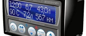
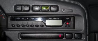
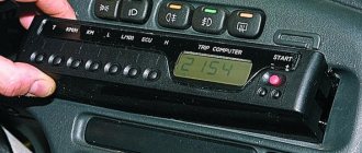
Trip computer (MC), shown in Fig. 37, is installed in a variant version instead of a clock in VAZ 2110, VAZ 2111, VAZ 2112 cars. The MK has 15 functions, divided into 3 groups (see Table 2). The group is selected using buttons 1, 2 and 3.
In each group, functions are divided into basic and additional. The main functions are navigated through the ring using buttons 1, 2 and 3. Additional functions are navigated through button 5. When the ignition is turned off, the computer is always in the “Current Time” mode. When the battery is removed, the clock progress and all accumulated parameters are retained for at least 1 month.
Diagnostics using additional tools
To diagnose cars, including the VAZ 2110, various equipment is used, which is connected to a special connector. Thanks to this equipment, which is not particularly complicated or expensive, you can get a complete picture of the condition of the car.
The service station uses a personal computer to which data from phase sensors is transmitted via a special cable.
Adapter for car diagnostics
Bluetooth devices have appeared on the market that allow diagnostics using a smartphone, tablet or laptop.
They work according to the scheme. The device is connected to the connector, the ignition is turned on and the diagnostic process begins. The data comes from phase sensors to the ECU. From it to a mobile device on which specialized software must first be installed.
This makes it possible not only to obtain more data, but also to present it in a more visual form. This method allows a driver, even with little experience in operating a car (in our case, a VAZ 2110), to obtain all the data about his car.
But most drivers prefer to carry out diagnostics at a service station. So that you are aware of the data that the on-board computer produces through RAM from the phase sensors, we will present the transcripts of common errors.
Part 1 Part 2 Part 3 Part 4
If problems arise with electrical equipment, they must be corrected immediately. Error code 1602 will indicate that not everything is in order in this matter.
Sometimes error 1602 can simply be reset and does not appear in the future. Socialists call such data “good.”
Error 1602 sometimes appears if:
- the battery was disconnected for some time;
- there was a voltage surge when starting the engine, for example, in cold weather.
But if error code 1602 appears all the time, you need to check the entire network. Perhaps there is a break. If error code 1602 constantly appears, you can try cleaning the battery terminals. Check if they are securely fastened. Didn't help, error 1602 still appears? Check the circuit. You need to start from the positive terminal of the battery. Start with the electrical fuse and fuse link.
Check the ground of the ECU, TPS. Sometimes it happens that the cause of error code 1602 is an alarm that can block the controller circuit and affect the readings of the phase sensors. In such a situation, you need to file a claim with the company that installed the alarm.
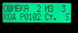
Error 0102 indicates a low signal level, which is reported from the mass air flow phase sensor.
Code 0102 will be stored in RAM memory in the following situations:
- low air consumption, which depends on the speed of rotation of the crankshaft;
- how open the throttle is;
- Several cycles have passed since the problem appeared.
If the error appears periodically, then you need to:
- check the condition of the air barrier;
- fastening the wiring block to the ECU;
- check IAC;
- clean the throttle pipe.
Another error that may occur is 0300. 0300 appears in cases where the RAM detects frequent misfires.
If error code 0300 is displayed constantly, then you need to check the following components:
- spark plug;
- nozzles;
- ignition system;
- increased or decreased compression levels may be the cause of code 0300;
- Also, code 0300 may appear in case of wiring failure.
You cannot ignore the appearance of error 0300. In the future, this may lead to deterioration in the performance of other nodes.
It is not difficult to master car diagnostics, in particular the VAZ 2110. It will extend the service life due to timely detection of faults detected by phase sensors.
Loading …
Adapter for car diagnostics
They work according to the scheme. The device is connected to the connector, the ignition is turned on and the diagnostic process begins. The data comes from phase sensors to the ECU. From it to a mobile device on which specialized software must first be installed.
ADJUSTING THE COMPUTER FUNCTION
Clock correction
Press button 4 in the “Current time” mode. At the sixth signal of the exact time, press button 1, this resets the seconds and rounds the clock readings.
Setting the current time (calendar)
- Press button 4 in the “Current time” (“calendar”) mode.
- Use buttons 5, 6 to set the desired hour (day).
- Press button 4.
- Use buttons 5, 6 to set the desired value for minutes (month).
- Press button 4 to complete the time (calendar) setting.
Correct operation
With the right approach, the installed BC will not cause problems. However, if it shows unreliable information, then it is worth removing the on-board computer and checking it for serviceability. How to remove the device is clear. After all, it has a disconnectable connector, so you need to dismantle it in the reverse order. The main thing to remember is that this is a fragile thing and can be broken.
After dismantling, you should check the integrity of the soldering and wires and eliminate any breaks . Afterwards, put the device where it was before and use the working device again.
Setting an alarm
- Press button 4 in Alarm mode.
- Use buttons 5, 6 to set the desired hour value.
- Press button 4. Use buttons 5, 6 to set the desired minute value.
- Press button 4 to complete the alarm setting.
- In the “Current time” mode, the alarm symbol will light up (the alarm is on).
* If the counter of any of the accumulated parameters (“Travel time”, “Travel time with stops”, “Total consumption”, “Trip mileage”) overflows, all accumulated ones, as well as calculated ones (“Average fuel consumption”, “Forecast”) are reset mileage on remaining fuel", "Average speed") parameters, with the appearance of a two-tone sound signal.
Turning off the alarm
- Press button 4 in Alarm mode.
- Press button 1 to turn off the alarm. “—.—” will appear in the digital digits, and in the “Current time” mode the alarm symbol will not light up (the alarm is turned off).
Adjusting the brightness of the indicator backlight
When the side lights are on, the illumination level is adjusted using the instrument scale illumination regulator. When the side lights are turned off, the backlight level is adjusted by software:
- — press button 4 in the “Traveling time with stops” mode. All single segments (pictograms) will be displayed on the indicator, which is a sign of the backlight level adjustment mode, and the digital digits will display a number corresponding to the backlight level as a percentage of the maximum value;
- — use buttons 5, 6 to set the required level of backlight brightness; press button 4 to end the brightness adjustment mode.
Source
Connection diagram
The process of diagnosing an ECU using a special scanner.
Electronic control units of the VAZ-2110 are the main tool for controlling and automating most processes in the car. To adjust the software, they often resort to replacing the “brains” with more “flexible” ones and reflashing the ECU.
First of all, it is necessary to clarify several terms that will be required when considering questions about changing the electronic control unit:
- Wiring compatibility . To replace it, the connectors on the old ECU and the new one will need to match.
- Software is a predetermined algorithm that can change depending on the needs or desires of the motorist.
- The hardware component is the electronic control unit itself, boards or other components that allow the systems associated with the ECU to function normally.
For the VAZ-2110 family there were two types of connectors. So, for the “brains” January 5.1.x, Bosch M1.5.4, Bosch MP7.0, and VS 5.1 there was a 51-pin connector, but for January 7.2(+), Bosch M7.9.7(+) and M73 - 81 -pin.
That is, the interchangeability of control units is caused by the pinout of the unit.
ECU January 7.2.
Differences
Fundamental differences between 81-pin blocks and blocks of previous generations:
- Overall body dimensions and weight have been reduced.
- New, more modern connectors with improved connection reliability.
- The controllers have built-in switches, therefore, instead of ignition modules, ignition coils can be used, which increase the reliability of the ECM as a whole.
- There is no software or hardware compatibility with any of the previously released units.
Even electronic control units from the same manufacturer will differ significantly in pinout. Therefore, the interchangeability of the “brains” will depend on the number of connector pins. Also, it is worth understanding that the firmware will play a big role. When changing the ECU, the motorist will have to reflash the unit for the correct operation of all vehicle devices.
ECU January 5.1.
A very important nuance remains that the software of the control unit must be compatible and comply with the type of injection, as well as the toxic standards laid down by the manufacturer.
Assignment of contacts of ECU Bosch M1.5.4, MP7.0 and January-5.1
Pinout of 55-pin ECU.
Let's look at the pinout of control units with 55-pin “brains”:
| Bosch M1.5.4 (1411020 and 1411020-70) January 5.1.1 (71) | Bosch M1.5.4 (40/60) January-5.1 (41/61) January 5.1.2 (71) | Bosch MP7.0 | |
| 1 | Ignition 1-4 cylinders. | Ignition 1-4 cylinders. | Ignition 1-4 cylinders. |
| 2 | . | Ground ignition wire. | . |
| 3 | Fuel pump relay | Fuel pump relay | Fuel pump relay |
| 4 | Stepper motor PXX(A) | Stepper motor PXX(A) | Stepper motor PXX(A) |
| 5 | Canister purge valve. | Canister purge valve. | |
| 6 | Cooling fan relay | Cooling fan relay | Left fan relay (only on Nivas) |
| 7 | Air flow sensor input signal | Air flow sensor input signal | Air flow sensor input signal |
| 8 | . | Phase sensor input signal | Phase sensor input signal |
| 9 | Speed sensor | Speed sensor | Speed sensor |
| 10 | . | General. Oxygen sensor weight | Oxygen sensor weight |
| 11 | Knock sensor | Knock sensor | Knock sensor input 1 |
| 12 | Power supply for sensors. +5 | Power supply for sensors. +5 | Power supply for sensors. +5 |
| 13 | L-line | L-line | L-line |
| 14 | Weight of injectors | Weight of injectors | Weight of injectors. Power "ground" |
| 15 | Control of injectors 1-4 | Oxygen sensor heater | Check Engine Light |
| 16 | . | Injector 2 | Injector 3 |
| 17 | . | Recirculation valve | Injector 1 |
| 18 | Power supply +12V non-switchable | Power supply +12V non-switchable | Power supply +12V non-switchable |
| 19 | Common wire. Weight of electronics | Common wire. Weight of electronics | Common wire. Weight of electronics |
| 20 | Ignition 2-3 cylinders | Ignition 2-3 cylinders | |
| 21 | Stepper motor PXX© | Stepper motor PXX© | Ignition 2-3 cylinders |
| 22 | Check Engine Light | Check Engine Light | Stepper motor PXX(B) |
| 23 | . | Injector 1 | Air conditioner relay |
| 24 | Stepper motor weight | Weight of stepper motor output stages | Power grounding |
| 25 | Air conditioner relay | Air conditioner relay | . |
| 26 | Stepper motor PXX(B) | Stepper motor PXX(B) | Weight of sensors TPS, DTOZH, DMR |
| 27 | Ignition switch terminal 15 | Ignition switch terminal 15 | Ignition switch terminal 15 |
| 28 | . | Oxygen sensor input | Oxygen sensor input |
| 29 | Stepper motor PXX(D) | Stepper motor PXX(D) | Oxygen sensor 2 input signal |
| 30 | Weight of sensors MAF, DTOZH, DPS, DD, DPKV | Weight of sensors MAF, DTOZH, DPS, DD, DPKV | Knock sensor input 2 |
| 31 | . | Reserve output high current | Rough road sensor input signal |
| 32 | . | . | Fuel consumption signal |
| 33 | Control of injectors 2-3 | Oxygen sensor heater. | . |
| 34 | . | Injector 4 | Injector 4 |
| 35 | . | Injector 3 | Injector 2 |
| 36 | . | Exit. Intake pipe length control valve. | Main relay |
| 37 | Nutrition. +12V after the main relay | Nutrition. +12V after the main relay | Nutrition. +12V after the main relay |
| 38 | . | Low-current backup output | . |
| 39 | . | . | Stepper motor РХХ © |
| 40 | . | Reserve input discrete high | . |
| 41 | Request to turn on the air conditioner | Request to turn on the air conditioner | Oxygen sensor heater 2 |
| 42 | . | Reserve input discrete low | . |
| 43 | Signal to tachometer | Signal to tachometer | Signal to tachometer |
| 44 | CO - potentiometer | Air temperature sensor | . |
| 45 | Coolant temperature sensor | Coolant temperature sensor | Coolant temperature sensor |
| 46 | Main relay | Main relay | Cooling fan relay |
| 47 | Programming permission | Programming permission | Air conditioner request signal input |
| 48 | Crankshaft position sensor. Low level | Crankshaft position sensor. Low level | Crankshaft position sensor. Low level |
| 49 | Crankshaft position sensor.High level | Crankshaft position sensor.High level | Crankshaft position sensor.High level |
| 50 | . | Recirculation valve position sensor | Programming permission |
| 51 | . | Request to turn on the power steering | DC heater |
| 52 | . | Reserve input discrete low | . |
| 53 | Throttle position sensor | Throttle position sensor | Throttle position sensor |
| 54 | Fuel consumption signal | Fuel consumption signal | Stepper motor IAC (D) |
| 55 | K-line | K-line | K-line |
Description of contacts ECU M7.9.7 / January 7.2
Let's look at the pinout of control units with 81-pin “brains”:
| № | Compound |
| 1 | 21114 - Not used / 21124 - Ignition coil 2 cylinders. |
| 2 | 21114 - Ignition 2-3. Control of the primary winding of the ignition coil, act. level is low. / 21124 — Ignition coil 3 cylinders. |
| 3 | Ignition circuit weight |
| 4 | 21114 - Not used / 21124 - Ignition coil 4 cylinders. |
| 5 | 21114 - Ignition 1-4. Control of the primary winding of the ignition coil, act. level is low. / 21124 - Ignition coil of cylinder 1. |
| 6 | Injector 2. Active level low |
| 7 | Injector 3. Active level low |
| 8 | Output to tachometer. |
| 9 | Not used |
| 10 | Fuel consumption signal |
| 11 | Not used |
| 12 | Battery, terminal 30 of the ignition switch. |
| 13 | Nutrition. Ignition switch terminal 15 |
| 14 | Main relay |
| 15 | Contact "A" DPKV |
| 16 | TPDZ |
| 17 | TPS mass / TPS mass, DND |
| 18 | Input - oxygen sensor |
| 19 | Input - knock sensor |
| 20 | Knock sensor weight |
| 21 | Not used |
| 22 | Not used |
| 23 | Not used |
| 24 | Not used |
| 25 | Bosch Only - High Current Output, Reserved |
| 26 | Bosch Only - High Current Output, Reserved |
| 27 | Injector 1. Active level low |
| 28 | Not used / DK2 heater control output |
| 29 | Not used / Engine cooling fan control output 2 |
| 30 | Not used |
| 31 | CE lamp, act. level low |
| 32 | Power supply TPDZ / Power supply TPDZ, DND |
| 33 | Power supply for mass air flow sensor |
| 34 | DPKV input, contact “B” |
| 35 | Weight of DTOZH / Weight of DTOZH, mass air flow sensor, 1 DC (UDK), 2 DC (DDK) |
| 36 | Mass of the mass air flow sensor |
| 37 | Signal input from mass air flow sensor |
| 38 | Not used |
| 39 | Signal input from DTOZH |
| 40 | Signal input from intake air temperature sensor |
| 41 | Not used |
| 42 | Not used / DND signal input |
| 43 | Not used |
| 44 | On-board voltage input at the main relay output |
| 45 | Phase sensor power output |
| 46 | Canister purge valve control output |
| 47 | Injector 4. Active level low |
| 48 | Oxygen sensor heater control output |
| 49 | Not used |
| 50 | Additional starter relay control output |
| 51 | Controller weight |
| 52 | Not used |
| 53 | Controller weight |
| 54 | Not used |
| 55 | Not used / Signal input DK2 (DDK) |
| 56 | Not used |
| 57 | Input for encoding calibration data options. The controller memory can contain 2 sets of calibration data; switching is performed by shorting to ground. |
| 58 | Not used |
| 59 | Speed sensor |
| 60 | Not used |
| 61 | Weight of output stages |
| 62 | Not used |
| 63 | On-board voltage input at the main relay output |
| 64 | Output “D” IAC |
| 65 | Output “C” IAC |
| 66 | Output “B” IAC |
| 67 | Output “A” IAC |
| 68 | Engine cooling fan relay control output, act. level - low |
| 69 | Air conditioner relay control output, act. level - low |
| 70 | Fuel pump relay control output, act. level - low |
| 71 | K-Line |
| 72 | Not used |
| 73 | Not used |
| 74 | Not used |
| 75 | Input request to turn on the air conditioner, act. level - high |
| 76 | Power steering request input, act. level - high |
| 77 | Not used |
| 78 | Not used |
| 79 | Phase sensor signal input |
| 80 | Weight of output stages |
| 81 | Not used |
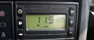
Standard on-board computer on the VAZ-2112: functions and operating instructions
On cars of the Tenth Family, a clock or computer is always installed next to the display unit. Nowadays such computers are called “on-board computers” (BC). When the ignition is turned off, the computer display shows the time, but this is not its only function! We will list all the capabilities of the on-board computer on the VAZ-2112, and the instructions supplied by VAZ will help us with this. Tables that are important during setup were copied from the instructions.
What bookmaker are we talking about? The answer is given in the video.
Types of bookmakers
On-board devices are divided into several types. Injection or carburetor devices are suitable for the VAZ 2110, depending on the type of power system for the car. Additionally, devices are divided into stationary, installed only in specially designated places, or universal, of any size, which can be placed in any convenient place.
Among other things, there are devices that are suitable only for one model. For example, VAZ 20199, but it does not work on VAZ 2110. This may cause the device to display data incorrectly. It’s worth remembering this when purchasing and purchasing an on-board computer that can be installed specifically on these models.
The most common and convenient devices for the VAZ 2110 are simple State 110-X5 devices, the price of which starts from 2-3 thousand rubles. The bortovik is compatible with the old panel and has a number of simple functions, such as information on fuel consumption, coolant temperature in the tank, estimated power reserve and mileage until the upcoming maintenance, coupled with decoding engine errors.
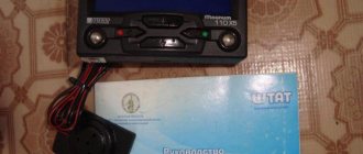
It is best to give preference to more expensive devices such as Omega 168, Orion or Mutltronics. Such devices have an expanded range of useful functions that will significantly simplify the operation of the car. And you won’t be scared by how much such an on-board computer costs. The maximum cost of advanced BCs, which come with a dashboard that simplifies installation, reaches 10-12 thousand rubles.
Programming instructions
We will change different settings. We’ll also try turning on the alarm, changing the brightness of the backlight, etc. Thus, programming a computer on a VAZ-2112 also applies to operation.
Setting up the fuel level sensor
The tank initially remains empty. Turn on the “Fuel level” function (2-5) and press button 4 for more than two seconds. Next we follow the steps:
- Press button 3 for one second until a sound signal appears;
- Fill the tank with three liters of fuel. Wait 10-20 seconds and repeat step 1;
- Repeat steps 1 and 2 until 39 liters are filled.
Activate the speed warning light
By pressing button 3 we turn on the “Average speed” function. Press key 4. Then use buttons 5 and 6 to set the required numbers. Finally, press button 4.
To disable the option, use a high threshold value: 190 or 200 km/h.
Changing the backlight brightness
Let's use function 1-3 “Time with stops”. Press button 4. Use keys 5 and 6 to make adjustments. Press button 4.
Alarm
Go to the “Alarm Clock” option (an additional function in the “Clock” list). Press button 4. Next, set the hour value (keys 5 and 6), press button 4, set the minute value (keys 5 and 6). By pressing button 4, the alarm clock is activated.
An alarm clock in a car is a necessary thing
All that remains is to figure out how to turn off the alarm clock. Complete all the steps before setting the hour value, and then press button 1. The alarm should turn off!
Disadvantages of the BC injector
Some VAZ 2110 models are equipped with a standard on-board computer. This model has a certain number of disadvantages and limitations. For example, the model interacts poorly with the electronic control unit (ECU) and does not allow receiving data through a special diagnostic connector. However, only motorists with on-board computers in the state face this problem. In addition, this can be treated with a standard flashing of factory settings.
If the BC is installed separately on the VAZ 2110, then it can be easily customized for yourself. If connected correctly, the device will not cause problems. If there are still difficulties, for example, the Check light comes on, but the diagnostics shows that such an error code does not exist.
This means that the contacts of the on-board computer may come loose or the electronic system may fail. You need to restart the bookmaker or turn it off for a few minutes. Next, we reconnect and configure the device according to the operating instructions.
- some models of on-board aircraft do not allow reading errors;
- incorrect connection of the computer to the VAZ 2110 can cause errors in the ignition system;
- shows incorrect fuel consumption values due to a faulty mass air flow sensor.
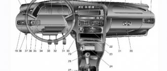
Removal and modification
Here's a quick look at the device and control panel icons. If for some reason she refuses, don’t immediately panic. Most often, the reason is the absence of contacts in some place in the wiring. But of course, if you wish, you can completely change or tune the panel.
For example, remove the cover and replace the light bulbs with brighter LEDs. Such a panel works brighter and the signals sent by the car will be more noticeable to the driver. If desired, you can install a more solid europanel, which will transform the interior.
To remove the panel you need:
- Disconnect the “-” wire from the battery;
- Remove the shield by unscrewing the screws;
- Remove the fastenings of the control panel to the trim, remove the instrument cluster from the socket;
- Remove the glass mask;
- Disconnect the wires from the block;
- Make changes to the instrument panel or replace it with a new one. Reassemble everything in reverse order.
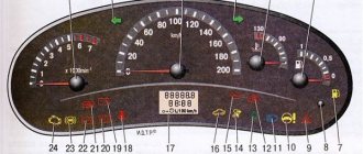
Designations of indicator lamps on the instrument panel of VAZ 2110 - 15.
Many car enthusiasts are faced with this seemingly simple question. What do the indicator lights on the instrument panel mean?
And what do we know, they all light up together only when the ignition is turned on, and when one of them lights up while driving, it becomes a little uneasy.
I didn’t know this myself when I switched to a “two” after the “seven”, half of the 2107 didn’t light up at all, so I didn’t know what it was and what it was for. And a friend of mine, after buying a car in Novorossiysk, even bought a whole book on VAZ , due to ignorance of these light bulbs.
The symbols on the instrument panels on all VAZs are almost the same, just the location is different.
Let's start in order.
1 — Coolant temperature, in degrees Celsius.
2 — Tachometer, engine speed.
5 — Speedometer, vehicle speed in km/h.
6 - Fuel level in the tank. When there are 5-7 liters left, a yellow light comes on - a warning or an icon with a picture of a gas station.
7 - Actually, this is an image of a gas station, signaling the need to refuel.
8 - Indicator lamp for turning on the dimensions.
9 — The brake fluid level is low, it may be leaking somewhere.
10 - Turn on the high beam.
11 - Clock adjustment knob (hours/minutes - switches when pressed), sometimes this knob serves as the function of switching the total mileage/day mileage (on panels with a narrow display).
12 — The display showing the total mileage/daily mileage is narrow on some models.
13 - Hazard warning lamp - “hazard light”.
14 - Check Engine, often indicated by this icon - this means a malfunction in the engine, it is recommended to stop the engine.
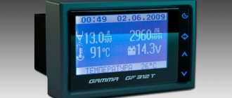
15 — Display with a clock (can show the outside air temperature if there is a temperature sensor).
16 - Malfunction in the battery charging system: loose or broken generator belt, generator malfunction, open circuit and other problems.
17 - Parking brake indicator.
18 - Insufficient oil pressure in the engine, it is recommended to turn off the engine and find the cause.
19 — Air damper light (on carburetor engines)
I’ll also add about the lamps on the additional panel in the dashboard of the VAZ 2110 - 12.
— The light marked with an arrow is a check for malfunction of the dimensions or brake lights. — Below is a brake pad wear indicator, if it lights up, check the brake pads, maybe it’s time to change them. — Seat belt warning light — this is clear from the picture.
On the other side from above:
— Low engine oil level — Low washer fluid level — Increased coolant temperature
This is how the review turned out. If some kind of lamp lights up and the signal beeps, do not panic. Usually these are small things.
Save this note to yourself on your social network by clicking on one of the buttons below.