One of the main systems that ensures safety when driving a car is the braking system. The most widespread are brake mechanisms that use the frictional force of different materials. Such mechanisms are installed on all cars, including VAZs belonging to the “Classic” family.
As an example of a classic VAZ, model 2107 will be used. The brake system of the VAZ-2107 includes working and parking systems. The task of the working component is to reduce the speed of movement of the car until it is completely immobilized.
It consists of two components: the first is the brake mechanisms, which act on the wheels, which is why their rotation decreases. The second component is the drive, through which the driver operates the mechanisms.
The parking component ensures that the wheels of one of the car's axles are locked, in the case of the VAZ-2107 - the rear axles, while the car is immobilized. The use of this brake prevents spontaneous movement of the car. This system uses a separate drive that acts on the rear axle mechanisms.
In more detail, what the brake system of the VAZ-2107 looks like is shown in the diagram:
Now let's take a closer look at the design of the VAZ-2107 brake system. First, let's go through the working component. Its drive is hydraulic and includes:
- Control pedal;
- Vacuum booster;
- Main cylinder;
- Tank for working fluid;
- High pressure pipelines;
- Rear axle bellows pressure regulator;
The use of liquid as a working element of the drive is due to a number of positive qualities: a complex system of levers for the drive is not required, the wiring of pipelines to the mechanisms is facilitated, the transmission of force from the driver’s foot is enhanced several times due to the vacuum booster.
Related link:
Insulation of VAZ-2107 for the winter
The working mechanisms on the VAZ-2107 are of two types: disc brakes are installed at the front, using calipers; drum-type mechanisms are used on the rear axle, which also includes a parking mechanism.
Now in more detail about the elements of this system. So, the pedal that the driver presses is located on the same axis as the clutch control pedal. To ensure that it can be returned to its original position, it is spring-loaded.
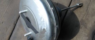
Vacuum brake booster
A rod connected to the amplifier is connected to the pedal. The design of the VAZ-2107 vacuum brake booster is quite interesting; it is shown in the figure:
The amplifier is a sealed container, internally divided into 2 chambers by means of a membrane. The chamber located closer to the pedal is called atmospheric, and the chamber separated from it by a membrane is called vacuum. The diaphragm itself is connected to the piston rod of the master cylinder.
The vacuum chamber is connected by a pipe to the intake manifold of the engine, where the vacuum comes from. The design also includes a follower valve controlled by the pedal rod, which does all the work.
When the pedal is released, this valve connects the chamber cavities through a channel, providing identical pressure. When the pedal is applied, the valve closes the channel connecting the chambers and opens the channel connecting the atmospheric chamber with the atmosphere. Since a vacuum is maintained in the second chamber, atmospheric pressure begins to put pressure on the membrane. Since it is connected to the piston rod of the master cylinder, due to the movement of the piston, fluid is displaced from the cylinder into the pipelines.
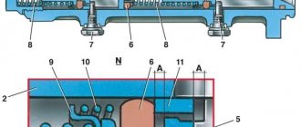
Design and principle of operation of VUT
The vacuum amplifier is a metal “barrel” consisting of the following parts (the numbering in the list coincides with the positions in the diagram):
- The body is cylindrical in shape.
- Pressure rod of the main brake cylinder.
- A cover connected to the body by point rolling.
- Piston.
- Bypass valve.
- Brake pedal pusher.
- Air filter.
- Buffer insert.
- Internal plastic housing.
- Rubber membrane.
- Spring for return of the inner housing with membrane.
- Connection fitting.
- Check valve.
- Vacuum pipe.
The internal cavity of the amplifier is divided by a rubber diaphragm into 2 working chambers
The letter “A” in the diagram indicates the chamber for supplying vacuum, the letters “B” and “C” are the internal channels, and “D” is the cavity communicating with the atmosphere. Rod pos. 2 rests against the mating part of the main brake cylinder (abbreviated as GTZ), the pusher pos. 6 is attached to the pedal.
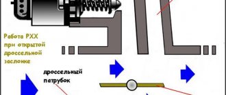
The unit is capable of operating in 3 modes:
- The engine is running, but the driver does not press the brake. Vacuum from the manifold is supplied through channels “B” and “C” into both chambers; the valve is closed and does not allow atmospheric air inside. The spring holds the diaphragm in its original position.
- Standard braking. The pedal is partially pressed, the valve releases air (through the filter) into chamber “G”, which is why the vacuum force in cavity “A” helps to press on the GTZ rod. The plastic body will move forward and rest against the piston, and the movement of the rod will stop.
- Emergency braking. In this case, the effect of vacuum on the membrane and housing is not limited; the master cylinder rod is squeezed all the way.
Due to the pressure difference in the two chambers, the membrane helps to put pressure on the master cylinder rod
After releasing the pedal, the spring throws the body and membrane back to their original position, and the atmospheric valve closes. The check valve at the inlet of the pipe serves as protection against sudden air injection from the manifold.
Gas breakthrough into the intake manifold and further into the brake booster occurs on extremely worn engines. The reason is a loose fit of the intake valve to the cylinder head seat. During the compression stroke, the piston creates a pressure of about 7-8 atm and pushes some of the gases back into the manifold. If the check valve does not work, they will begin to penetrate into the vacuum chamber, reducing the efficiency of the VUT.
Video: how a vacuum brake booster works
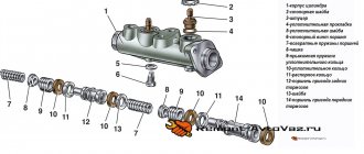
Brake master cylinder
The master cylinder is connected to the booster. This element is a housing to which the supply and return pipelines from the fluid reservoir are connected, and 3 pipelines leading to the brake mechanisms exit. There is one pipeline leading to the front brake mechanisms, and only one to the rear, leading to the regulator.
Inside this housing there are pistons that push the liquid into the pipelines. One of them is connected to the amplifier diaphragm rod. These are the main elements of the drive. The detailed design of the brake master cylinder is shown above.
Related link:
Homemade pre-heater for a VAZ car engine
VAZ 2107 | Adjusting the brake drive
Adjust the free play of the brake pedal with the engine not running.
Repair of VAZ 2107 (Zhiguli): Checking and adjusting the brakes
7.1.1 Checking and adjusting brakes Checking pipelines and connections Checking the functionality of the vacuum booster Adjusting the brake drive Adjusting the parking brake Checking the functionality of the pressure regulator Adjusting the position of the pressure regulator Bleeding air from the hydraulic drive...
7.1.2 Checking pipelines and connections To prevent sudden failure of the brake system, carefully check the condition of all pipelines: - metal pipelines should not have dents, cracks and should be located away from sharp edges that could damage them; — brake hoses should not have through cracks...
7.1.3 Checking the operation of the vacuum booster Fig. 7–2. Vacuum amplifier: 1 - tip mounting flange; 2 - amplifier housing; 3 - rod ; 4 - cover; 5 - piston; 6 — amplifier mounting bolt; 7 - spacer ring; 8 — valve spring support cup; 9 - valve; 10 — valve support cup; 11 — support cup of the return pr…
7.1.4 Adjusting the brake drive Fig. 7–3. Brake pedal: 1 — vacuum booster ; 2 - pusher; 3 — brake pedal; 4 — brake light switch buffer; 5 — switch nut; 6 — brake light switch; 7 — pedal release spring; 8 – master cylinder Free play of the brake pedal when the engine is not running...
7.1.5 Adjusting the parking brake NOTE Since the beginning of the 90s, the design of the toothed sector of the parking brake lever has changed - the initial tooth of the sector has become double and the adjustment procedure has changed, noted below in the text. If the parking brake does not hold the car on a slope of 25% when moving ...
READ Peugeot 408 windshield replacement
7.1.6 Checking the operation of the pressure regulator Place the car on a lift or inspection ditch, clean the pressure regulator and remove dirt from the cover. Carefully remove the protective boot from the pressure regulator, remove any remaining grease and clean the torsion bar-piston connection. Ask an assistant to press the brake pedal with a force of 686–78...
7.1.7 Adjusting the position of the pressure regulator Fig. 7–4. Installation diagram of the rear brake pressure regulator and its adjustment: 1, 2 — bolts securing the pressure regulator to the bracket; 3 — protective cap; 4 — torsion lever of the regulator drive; 5 — bracket for attaching the lever to the body; 6 - piston; 7 — connection rod with bracket...
7.1.8 Removing air from the hydraulic drive Air that gets into the hydraulic drive of the service brake system when replacing pipelines, hoses, sealing rings or leaks in the hydraulic drive causes an increase in the working stroke of the brake pedal, its “dips” and “softness”, and also reduces braking efficiency. Before removing air from...
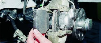
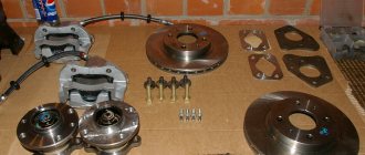
Caliper device
Let's move on. The front axle mechanisms are disk ones, consisting of calipers with the main brake elements - pads, and brake discs.
A caliper is a body with cylinders made in it for the pistons. This model has two of them, one for each block. The support structure is shown in the figure.
The caliper pistons have the form of a glass, which is placed in their cylinders, but they can move along it. To prevent fluid leakage, the pistons are equipped with o-rings.
Pads are small metal plates onto which linings made of friction material are glued.
The brake disc is made of metal for better adhesion to the surface of the pads; its side surfaces are well processed so that there are no protrusions or shells on them.
The VAZ 2107 brakes work like this: the fluid moves into the caliper cylinders, where it begins to push out the pistons. They come out of the cylinders, pressing the pads against the disc.
How to check when purchasing
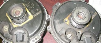
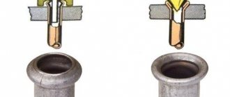
Before purchasing a new spare part, its quality can be assessed visually - there should be no obvious damage to the elements: body, boots, casings, protruding parts of the pusher and rod. If it is sold with a fitting and a check valve, then we check it for leaks (valve). To do this, you need to blow into the fitting from the hose connection side; if air does not come out on the other side, then the valve is working. You can also use a rubber bulb - squeeze the air out of it, insert it into the fitting on the vacuum connection side; if the bulb remains compressed, the valve holds.
In the same way we check the mechanism itself. For this you will need a soap solution and compressed air. We carry out this test in a garage environment, so after purchasing an amplifier, be sure to take a receipt from the store so that you can return it if it is found to be faulty.
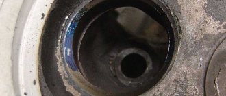
In the garage we wash the place where the two halves of the mechanism are rolled, the boots, the cuffs, all the places where there may be air leaks. We take out the fitting. We direct compressed air from the compressor into the resulting hole and observe. Where bubbles appear, the seal is broken, the vacuum amplifier is defective.
It is important that you cannot insert a compressor hose into the hole from the fitting; the pressure in it is high; it can damage the membrane and other elements of the mechanism. This process is clearly visible in the video below.
Rear axle brake mechanism
The brake system of the VAZ-2107 rear axle has a different device. All its elements are hidden inside the brake drum:
The working brake cylinder of the VAZ 2107 has the following device: there is a body, also known as a cylinder, with two pistons placed in it. When exposed to fluid pressure, they come out of the cylinder.
The pads are metal, made in the shape of crescents, with friction clutches glued to their upper edge. The pads installed on the hub form a ring.
In the lower part, the pads are installed in the seats made under them, and in the upper part - in the grooves made in the pistons. To prevent the pads from moving apart spontaneously, they are tightened with springs. The parking brake mechanism is also located there.
On top of all this there is a drum mounted on the hub shaft. When braking, the fluid pushes the pistons, and since the pads fit into their grooves, this movement of the pistons is accompanied by the divergence of the pads. At the same time, they are pressed towards the drum and the rotation slows down.
Related link:
Causes of detonation of VAZ engines and solutions
Replacement for VAZ 2106-07
For this we need:
- Socket wrench or socket "13"
- Screwdriver
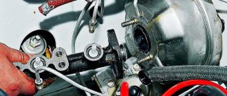
How to replace a vacuum booster on a classic
1. We climb into the cabin and disconnect the pin lock that connects the brake pedal to the amplifier
2. Pull out the pin, freeing the VUT pusher from the pedal assembly
3. Using a socket or wrench, unscrew the nuts securing the vacuum unit to the wall of the engine compartment
4. Go under the hood and unscrew the two nuts of the brake master cylinder (MBC) from the vacuum booster housing
5. Carefully bend the brake cylinder away from the booster so as not to damage the brake system pipes. We check the seat of the GTZ to the VUT; if it is stained with brake fluid, it is advisable to replace the cylinder or repair it, eliminating leaks of the end seal. Otherwise, the diaphragm of the new vacuum seal will lose its elasticity from contact with the brake fluid and will break.
6. Remove the mechanism from the wall of the engine shield
Installation is carried out in reverse order. Don’t forget to adjust the stem offset (it should be 1.05-1.25 mm) and the free play of the pedal. Before installing a new part, you need to check it before purchasing. Let's talk about how to do this now.
Video of self-replacement of the vacuum brake booster on a classic:
Parking system
Although it engages the mechanism of the rear axle wheels, it is in no way connected with the working mechanism. It uses a cable as a drive connected to the handbrake located inside the car.
Under the car, this cable is divided into two parts, going into the rear axle mechanisms. Inside, the ends of the cable are connected to the drive lever, which in turn is connected to a spacer bar. The drive lever is connected to one of the pads.
When the handbrake is engaged, the cable pulls the lever, and since it rests against the bar, the pads are released. The toothed sector of the handbrake fixes the position of the lever when the pads are spread apart.
Pressure regulator
It is installed in the rear wheel drive and not only distributes fluid to the mechanisms, it also prevents possible skidding due to different forces on the mechanisms. This is done by limiting the supply of pressure to the mechanisms, depending on the position of the car body relative to the bridge.
The regulator is driven by a rod, one end of which is fixed to the rear axle, while it itself is fixed to the body. As the load on the rear axle increases, the body changes position relative to the axle; as a result, the rod puts pressure on the regulator piston, which adjusts the pressure supplied to the mechanisms.
The brakes stopped working
In the worst case scenario, the brake booster control valve fails completely, resulting in complete inoperability of the brake system. Fortunately, such an outcome is unlikely. But if suddenly it does occur, carefully stop the car, tow it home and contact a qualified specialist in the diagnosis and repair of brake systems. Depending on the severity of the case, the matter may be limited to only replacing the valve, but serious repairs of the entire brake system may be required.
The brake booster control valve is an important element of the braking system, ensuring driving safety. That is why the presence of the described symptoms should not be ignored or postponed “for later”. Contact a qualified mechanic who can professionally diagnose and repair your vehicle's brake system.
The principle of operation of the VAZ-2107 brake system
If it is necessary to reduce speed, the driver presses the pedal. Its force is transmitted to the amplifier valve, which opens the required channel to supply atmospheric pressure to the membrane. The membrane is connected to a rod connected to the piston of the main cylinder. This rod displaces fluid into the pipelines leading to the operating mechanisms. Since the liquid is not compressed, all force is completely transferred to the mechanisms.
The liquid presses on the pistons of the working cylinders, and as they move out, they unclench (on drum bellows) or press the pads (on disk bellows) to the disk or drum connected to the wheel hubs. Due to the friction of the pads on the discs (drums), the rotation slows down.
Related link:
How to start a VAZ engine in winter
How to check on a car
Method 1
With the engine off, press the brake pedal several times. With each press you will feel an increase in the force applied to the pedal. On the fifth press, fix your foot on the brake in the pressed position. We start the engine, it should fall a little. The force with which you press should decrease and the leg will “sag” a little.
If this happens, then everything is fine, the amplifier is working. Because with each press the vacuum in the chamber decreases, you have to press the pedal harder to push it completely. Having started the engine, air is sucked out of the chamber by the intake manifold through a hose, a vacuum is formed, the vacuum unit begins to work, and feels relief when the pedal is held down. Under the influence of the efforts of the leg, it “fails”.
Method 2
We started the engine, let it run for a minute and turned it off. We hit the brakes. If at the first press it, as it should, easily “falls” all the way, and with subsequent presses it becomes more and more difficult to push it all the way, then the amplifier is working.
Having turned off the internal combustion engine, the check valve closes, maintaining a vacuum in the amplifier chamber. The first time you press it, it engages the diaphragm and you press the pedal with ease. With subsequent presses, the pressure in the chambers is equalized, you need to make more efforts to “drown” the pedal all the way.
Method 3
With the engine running, press the brake. Keep the pedal pressed and turn off the engine. Without removing your foot, you will feel that the pedal begins to resist your pressing more and more every minute, which means that there is an air intake, the vacuum seal is not working properly.
In this case, it is not the tightness of the mechanism elements that equalizes the pressure in the chambers, and since there is no source of vacuum, the engine does not work, the system tries to push the rod to its original position. You feel an increase in pressure on your leg. To keep the pedal in the fully depressed position, you need to press harder on it.
Video on how to independently check the vacuum booster on a Lada:
After such checks, you need to remove the part from the car and replace it with a new one. How to do this - read below.
Types of maintenance work
Despite the fact that the system is not so complicated structurally, it requires periodic maintenance, including:
- Checking the fluid level in the system;
- Checking the degree of wear of friction clutches, pads, discs, drums;
- Bleeding the system to remove air;
- Checking the condition of the handbrake cables;
- Adjustment of cable tension;
- Adjusting the rear brake adjuster;
Before each trip, you must always check how much brake fluid is in the VAZ-2107 system. An insufficient amount of it can lead to the fact that the efficiency of the system can be significantly reduced due to air getting inside the pipelines. In addition, a decrease in level may indicate damage to pipelines and fluid leakage.
The elements of the mechanism should be checked every few months, this is especially true for the pads, since they wear out quite intensively. If necessary, worn elements are replaced.
If air gets inside the drive of the working system, pumping is performed, as a result of which the air is expelled from the system.
Loosening the tension of the parking brake cables can lead to its failure, so you need to periodically monitor it and, if necessary, restore the tension.
Symptoms and diagnostics
If the VUT malfunctions, the force on the pedals during braking may increase many times over. Driving under these circumstances is unsafe. All symptoms must be immediately diagnosed and the broken unit repaired.
Typically, the vacuum booster is not checked during routine maintenance, so it is important to watch for the following symptoms:
- The pedal became hard. The main indicator that the VUT is worn out or is not working correctly. This may happen gradually or happen suddenly. In addition, the pedal may be positioned higher than usual.
- The braking distance has lengthened. This occurs because it is impossible to obtain the force on the master cylinder rod necessary for the design speed of stopping the vehicle.
- The engine stalls when the brakes are applied. This occurs when the amplifier diaphragm has lost its seal and allows air to leak past the seals. In addition to reduced braking ability, engine stalling can cause major problems on the road.
- The brake system stops working. The failure may be due to a malfunction of the VUT valves.
Features of the braking system
One of the features of the VAZ-2107 brake circuit is the presence of a dual-circuit system. The essence of a dual-circuit system is that the working drive is divided into two parts, each of which supplies fluid to only two mechanisms, while the circuits do not interact with each other.
The presence of two circuits ensures the operability of the brakes of at least two wheels in the event of depressurization of one of the circuits. That is, even if the pipelines of one circuit are punctured, the second will remain fully operational, which will ensure the functioning of the brakes.
In the VAZ-2107, the circuits are divided in such a way that the drive of the front axle mechanisms is separated from the drive of the rear mechanisms. This allows you not only to maintain the functionality of the system when one of the circuits fails, but also to pump each circuit separately. That is, if one of the circuits is airy, then it needs to be pumped, but it is not necessary to service the second one.
Related link:
Choosing a battery for a VAZ-2107 car
This is only general information about how the VAZ-2107 brake system works, and does not include all the details on its maintenance and repair. In general, the brakes of this car work quite well, although some elements of it cause complaints from car owners.
Article on the topic - Bleeding VAZ brakes
Possible mechanism malfunctions
The first sign of a breakdown of the brake system vacuum booster is an increase in effort when pressing the pedal (if the device is in working order, pressing the brake pedal is soft and smooth).
In this case, the brake mechanism continues to work, but causes inconvenience in driving. The driver needs to make more and more efforts to reduce speed in a timely manner. The part in question cannot be repaired, so if it malfunctions, it will need to be replaced. If you do not replace the vacuum booster on the VAZ 2107, then such operation of the car may result in an accident. The design of the device in question includes the following parts:
- steel body or base;
- valve;
- polymer membrane;
- rubber membrane.
The following types of malfunctions of the mechanism in question are distinguished:
- Damage inside the device. Typically, internal failures include damage to the diaphragm, as well as wear of the rubber base. In the event of such malfunctions, air bleeding will occur.
- The appearance of a crack in the membrane, as well as a complete violation of its integrity.
- Failure of the valve mechanism.
- The hose that connects the mechanism to the engine intake manifold is damaged. Damage usually occurs at the joint, often due to a loose clamp. It is easy to identify such a breakdown, since it will cause signs of hissing.
The hissing does not always appear, but only when you press the pedal, so it is not difficult to identify a system malfunction. At one point, if such a breakdown is not repaired, the brake hose may become damaged, which will cause the brakes to disappear.
The brake master cylinder is connected to the booster, so when replacing the device, these parts should be disconnected. Before replacing the vacuum seal, you will need to make sure that the amplifier is really faulty and cannot be used in the future.