You were looking for installation of a carburetor on the eye of a VAZ 2108 - we suggest you come to us. On our website you will find a video of DIY car repair. How to repair a car yourself at home. We will help you with repairs and repair the car yourself. We know how to restore a car with minimal investment. I have attached video instructions.
Category: Car repair video
Laughter in the topic: Abramovich scolds his son: - Why did you get a stake for writing an essay? What was the topic? - “Imagine that your dad is a millionaire!” - Are you crazy? – the oligarch could not restrain himself. “That’s what I wrote...
Published by Admin: at the request of Matthias
Car owner criticism: Dynamics. It’s very responsive and you don’t have to push it to the cutoff to get the power out – I’ve never turned it over 4 thousand. I haven’t measured it up to a hundred, but it feels like it could well fit within the rated 7.9 seconds. But the car is not for street show-off, I was ill as a child :) The ergonomics of the space are good. CPB is even better. But the fact that CPB thinks for a second and a half after pressing the gas... in general, this feature almost became the cause of an accident already during the test drive. Well, you know, I’m somehow used to the fact that the car drives if you press the gas. Fuel efficiency is in city mode with a constant climate during the break-in period (1200 km mileage) for 192 hp. consumption of 10.4 liters, which is steadily decreasing, is steep. I haven’t taken any measurements along the route, but the opportunity will arise soon. Taking into account that the previous car was 98 hp. I ate more and weighed half as much, which is impressive. And not even because it is much cheaper, but because a full tank lasts a long time - no time to waste at the gas station. The i-stop system - if necessary, can be easily adjusted by under-pressing the brake - enough for the car to stop, but the i-stop does not work. Or you can turn it off altogether. Maybe for some this system is unimportant. But for me, on the contrary, it’s extra seconds of relaxation of silence at a traffic light. Light - daytime lights, dimensions, low beam, high beam, PTF included. Daytime ones are not LEDs, but they don’t consume more. And for my personal taste, a separate strip of LEDs does not decorate the car. Either in the headlight or in the bumper. Safety – 5 or 6 airbags. I don’t use Isofix - a regular chair is more comfortable, and the safety is the same according to all tests. And, by the way, the space between the seats is such that you no longer look at the back of the front seat with horror. And the child can no longer reach the pocket of the front seat. And friends under two meters, the three of them with a chair in a row, do not break off day after day. Get into a tricky one - compare. Insurance price is 55 thousand (9.5 years of driving experience, no franchise, etc. + VIP package such as roadside assistance, evacuation, sudden emptiness in the gas tank). All other things being equal, the minimum wage for a Forester is a comprehensive insurance with a salon discount of 136 thousand. Ha Sportage 66. Yes, the central joystick is really convenient. You quickly learn how to operate “blindly”.
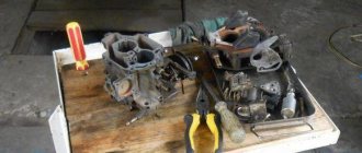
Those who follow my blog know that I have been busy setting up my workshop for the last couple of years. As a result, I completely neglected my two machines, which I sometimes regretted very much(
But with the onset of 2022, I decided to take up Okushka in earnest, because walking in such frost is not comme il faut... In short, after the move, the car drove exclusively suspended from the tractor, the engine was started (God willing, I remember) a couple of times, so as not to stagnate. Several problems surfaced at once: - The short drive, which was made from the original slide, was mercilessly torn out of its support - the gears can no longer be engaged. — The engine starts very hard, I blame the carb (I disassembled it and tuned it crookedly) — The section of the engine compartment braid responsible for powering and controlling the wiper motor melted. — The gas tank is leaking. — “Carlson” does not start, I had to put a toggle switch and turn it on forcibly. — The interior smells of exhaust and gasoline. — The choke cable has been torn out. — For some reason, the doors are sagging a lot and don’t close well (( — The clapper door is very rusty, it needs to be replaced... (ready to buy in St. Petersburg)
Models of carburetors for OKA cars
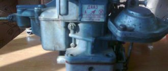
There are several modifications of OKA cars. The very first car of this brand was model 1111. It was produced at the VAZ and KamAZ factories. This model had an engine capacity of 0.65 liters and was equipped with a DMZ brand carburetor, which was produced at the auto parts plant in Dimitrovgrad.
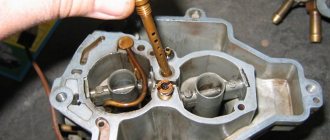
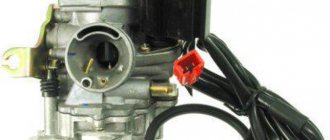
Main elements of the DAAZ 1111 carburetor for the OKA car
Then a new OKA car model appeared - 11113. The engine capacity of this car was slightly larger and amounted to 0.75 liters. Accordingly, the carburetor has also changed slightly. Model 11113 is equipped with DAAZ 1111 carburetors. This device is produced at the same plant in Dimitrovgrad. This carburetor differs from its predecessor only in the increased size of the mixing chamber. In all other respects, the device has not undergone any changes.
How to install the unit in place
You can assemble and reinstall the carburetor in the same way as you disassembled it, performing all the steps in reverse order.
- The carburetor is installed in its place, the mounting bolts are tightened.
- The pipes through which fuel is supplied are attached. The gas cable is connected to the throttle lever.
- The wiring is attached.
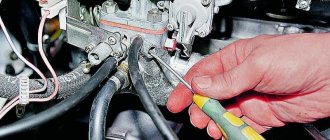
- A vacuum hose is connected to the ignition distributor, and the EPHH limit switches are combined.
- After installing the carburetor, it is adjusted.
Common carburetor malfunctions and their causes
- the carburetor fires. This is the most common malfunction associated with the carburetors of OKA vehicles. Usually the problem occurs due to low-quality gasoline. Because of it, a too lean fuel mixture begins to flow into the carburetor, after which the driver hears a loud bang under the hood, reminiscent of a pistol shot. To fix the problem, you should drain the low-quality fuel, change the gas station and clean the carburetor jets;
- excess gasoline in the carburetor. If too much gasoline enters the device, it is very difficult to start the car: the engine starts, but immediately stalls. To eliminate this problem, you need to fine-tune the carburetor, and if the problem persists, install a new set of spark plugs;
- there is no gasoline in the carburetor. If gasoline does not enter the carburetor, the car simply will not start. Typically, fuel stops flowing due to a blockage in one of the chambers of the device or due to poor adjustment. There is only one solution: remove the carburetor, completely disassemble it and wash it;
- Condensation has formed in the carburetor. This problem is rare, but it cannot be ignored. Most often, condensation appears in the carburetor in winter, during severe frosts. After this the car starts very hard. If you still manage to start, you need to warm up the engine properly for 10–15 minutes. Usually this is enough to completely eliminate condensation.
Cleaning the carburetor from carbon deposits and dirt
Most carburetor problems occur due to poor quality fuel. This is what causes plaque and soot to appear. It also causes blockages in the fuel channels. To eliminate all this, you will have to use a special cleaning fluid for carburetors. It is a spray can. The cylinder is usually accompanied by a set of nozzles for flushing the carburetor channels. There are many manufacturers of fluid, but HG3177 fluid is especially popular among car enthusiasts, allowing you to perfectly flush the carburetor in a few minutes.
Carburetor flushing fluid HG3177 is very popular among car enthusiasts
Tools and Supplies
- rags;
- several toothpicks;
- a piece of thin steel wire 30 cm long;
- compressed air cylinder;
- protective rubber gloves and glasses;
- set of open-end wrenches;
- flat screwdriver;
- carburetor cleaning fluid.
Sequencing
- Once removed from the vehicle, the carburetor is completely disassembled.
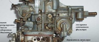
Completely disassembled and prepared for cleaning, the DAAZ 1111 carburetor for the OKA car - All clogged channels and holes are carefully cleaned using toothpicks. And if the carbon deposits are too strongly welded to the walls of the fuel channel, then steel wire is used to clean it.
- After preliminary cleaning, a nozzle with the thinnest tube is put on the can of liquid. Liquid is poured into all fuel channels and small carburetor openings. After this, the device should be left alone for 15–20 minutes (the exact time depends on the type of flushing liquid used and to clarify it, you should read the information on the can).
The thinnest nozzle for a can of carburetor cleaning fluid - After 20 minutes, the fuel channels are purged with compressed air from a can.
- All other contaminated carburetor parts are treated with liquid. The spray is sprayed without a nozzle. After 20 minutes, the parts are thoroughly wiped with a rag and the carburetor is reassembled.
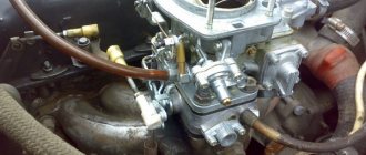
Carburetor "Oka"
The power units of the Oka car 1111 and 11113 were equipped with a carburetor power system. Now such a system is outdated and not used, but at the time of the start of production it was a priority; injectors were not used on domestic cars of those years of production.
The main element of such a power system is the carburetor. VAZ-11113 and its “junior” version received their own separate carburetor manufactured by DAAZ. This unit could not be simply borrowed from other models due to the fact that the Oka engines are 2-cylinder, and the performance indicators of the carburetor of the same VAZ-2108 simply did not meet the required requirements.
But the designers took the DAAZ-2108-1107010 from the Eight (aka Solex) as a base and based on it they created the DAAZ-1111-1107010, which was installed on the Oka.
It is noteworthy that when creating the Oka carburetor, not only Solex was used; some design solutions were also borrowed from Weber and Ozone carburetors.
The VAZ-11113 carburetor is similar in general construction principle to the Solex from the VAZ-2108, but there are some features, for example, in the Oka unit on the body there are two plugs, by removing which you can get to the fuel jets without disassembling the carburetor itself .
Construction and components
The Oka carburetor is a two-chamber carburetor with an idle speed solenoid valve (XX). This valve is the only electronic component.
The Oka carburetor includes 3 main parts:
- Lid;
- Main building;
- Throttle body.
These components are connected to each other with bolts.
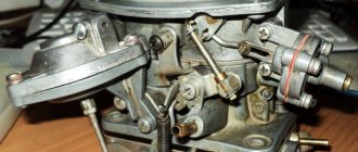
Lid
The cover contains fittings for connecting the fuel supply lines from the pump and draining the excess (return). To further clean the supplied gasoline, a small mesh filter is installed under the supply fitting.
An air damper is installed in one of the wells of the cover, the axis of which is connected by a cable to the handle for forced enrichment of the air-fuel mixture installed in the cabin (the so-called “manual choke”).
There are also studs on the cover to secure the filter housing.
Main building
The main working part of the carburetor.
It contains:
- GDS (main dosing system) with diffusers;
- float chamber;
- Acceleration pump;
- Economizer and inertial enricher;
- XX system with electronic valve;
This component is intended for dosing the amount of fuel depending on the operating mode of the engine and mixing gasoline into the air, ensuring stable operation of the power plant at idle.
Damper body
Two dampers are installed in the throttle body (1st and 2nd chambers). Structurally, it is made in such a way that the cable coming from the gas pedal is connected to the lever of the axis of only the damper of the primary chamber. The influence on the second damper is carried out through levers connecting both dampers.
Because of this device, the dampers open asynchronously, that is, first the throttle of the 1st chamber is activated, which pulls the damper of the 2nd chamber. This allows you to turn off the 2nd chamber at low engine loads to save fuel.
The Oka carburetor is adjusted using quality and quantity screws.
VAZ 11113
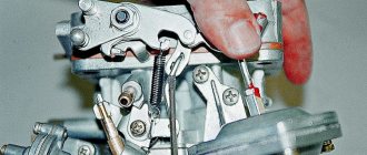
Adjusting the carburetor drive
Performed when replacing the carburetor
, as well as when drive parts are worn or replaced.
- When the gas pedal is fully pressed, the throttle valves should be fully open, and when released, they should be closed.
- If this is not the case, by unscrewing or tightening the adjusting nuts on the front end of the drive cable (carburetor side), we achieve the correct position of the throttle valves.
- The tension of the cable with the pedal fully released is checked as follows: we pull the cable in the middle of the branch near the carburetor by about 10 mm, while the throttle valves should not open. If you pull the branch back a large amount (about 15 mm), they should begin to open slightly.
Adjusting the fuel level in the float chamber
Performed when replacing a needle valve or float (see also “Diagnostics of engine malfunctions”).
- We remove the carburetor cover (see “Disassembling the carburetor”) and measure the protrusion of the needle valve above the cover, which should be 10 mm. If this is not the case, replace the gasket or valve with gasket.
- Having placed the float with its lower part on a flat surface, measure the distance from it to the center of the float axis. It should be 23.1 mm. We adjust the size by bending the lever.
- We measure the distance from the tongue to the top plane of the float, which should be 2.0 mm.
- A drill can be used as a gauge.
- We adjust the distance by bending the tongue. In this case, its supporting surface must be perpendicular to the axis of the needle valve.
Adjusting the starter
Performed on a removed carburetor.
- When turning the choke control lever counterclockwise all the way, the choke should close completely. If it does not close, eliminate the cause of the jam (or straighten the deformed valve).
- With the air damper completely closed, the throttle valve of the first chamber must be slightly open to the starting gap C (see figure).
- This gap is adjusted by turning the screw on the throttle drive lever with a thin slotted screwdriver.
- With the air damper completely closed, press manually (you can use a screwdriver, stick, etc.) on the trigger rod until it stops. In this case, the air damper should open slightly to the starting gap (see table above). We use a drill as a gauge.
- To adjust the gap, use an “8” wrench to loosen the lock nut of the screw located on the starter cover. Inserting a thin slotted screwdriver into the slot, unscrew (to increase the gap) or tighten (to decrease the gap) the screw, and then tighten the locknut.
Starting device: 1 - starting device lever; 2 — throttle valve; 3 - thrust screw for opening the throttle valve; 4 — lever on the axis of the throttle valve of the first chamber; 5 — starter control cable: 6 — lower edge of the cam groove; 7 — upper edge of the cam groove: 8 — air damper spring; 9 - air damper: 10-lever on the air damper axis; 11 — trigger diaphragm rod: 12 — trigger diaphragm: 13 — diaphragm thrust (adjusting) screw; 14 — screw for fastening the trigger lever; B - starting gap of the air damper; C - starting gap of the throttle valve.
Adjusting the idle system
Performed during maintenance or engine malfunctions (see “Diagnostics of faults”).
- The adjustment is performed on a warm engine. At the factory, the engine is adjusted to a minimum crankshaft speed of 820-900 rpm and a carbon monoxide (CO) content of 0.5-1.2%, after which a restrictive plastic sleeve is pressed onto the screw head. If by turning the bushings it is not possible to restore the factory adjustment parameters, we unscrew the screw, breaking the bushing, then by rotating the quantity screw we set the crankshaft speed, and by turning the quality screw we set the content of carbon monoxide in the exhaust gases.
- When you press the gas pedal, the engine should increase the crankshaft speed without interruption, and when you release the pedal, it should not stall.
- When turning the quantity screw clockwise, the crankshaft speed increases.
- When turning the quality screw clockwise, the CO content in the exhaust gases increases.
Design features
Despite the fact that the Solex from the Eight was taken as the basis for its creation, the Oka carburetor has some design features:
- The float and shut-off needle are separated. The first element is installed in the float chamber, the second is located in the lid. Because of this, the technology for adjusting the fuel level differs from the usual Solex;
- There is only one float chamber, and it is located on the side of the main dosing system (and not on the sides, like the Solex);
- The float is fixed in the chamber in such a way that a constant normal supply of gasoline is ensured during acceleration and upward movements;
- The calibration (hole cross-section) of the jets is smaller than that of the DAAZ from 2108.
As for the differences between the carburetors of the Oka models 1111 and 11113, they only come down to different calibrations of the jets.
Model 1111 uses fuel jets with a calibration of 95 (on the 1st and 2nd chambers) and air jets with a calibration of 190 (1st chamber) and 95 (2nd).
Version 11113 has 95 fuel jets (on both chambers) and 170 (1st), 85 (2nd chamber).
Since the dimensional parameters of Solex jets are identical and only the sections differ, it is possible to upgrade the Oka carburetor to increase power by installing jets of larger sections (but at the same time, gasoline consumption will also increase).
Fuel tank
Fuel tank 38 is stamped and welded from two steel halves. To increase corrosion resistance, the tank is tinned with POS 35 on both sides and painted with black enamel. Fuel tank capacity is 30 liters, including fuel reserve.
The tank is installed under the body floor and secured with four nuts to the body welded bolts. On the side of the main muffler and exhaust pipes, the tank is covered with a screen that protects the fuel in the tank from heating. The filler neck 16 of the tank is located in a niche in the rear part of the right side of the body and is closed with a sealed plastic plug 14. The plug has a torque limiter (on some cars a lock may be installed in the plug). The filler neck is connected to the fuel tank pipe with a hose 18 made of petrol-resistant rubber.
To prevent fuel leakage during refueling, the upper part of the filling pipe is connected to the tank nozzle with a rubber hose 13, through which air is forced out of the tank during refueling.
Fuel level sensor 37 with a fuel receiving tube is attached to the top of the fuel tank through a sealing gasket with nuts. The fuel receiving tube has a strainer 36. When there is remaining fuel reserve in the tank, the float lever 35 closes the contacts of the fuel reserve indicator lamp. A fuel level indicator with a fuel reserve warning lamp is installed on the instrument cluster in the vehicle interior.
For ventilation and access to atmospheric air, the fuel tank has a ventilation hose 12, made of a polyvinyl chloride tube with a tip 34 at the end. The hose is connected to the tank nozzle, has a loop along the filler neck and is then laid on hooks along the rear edge of the tank. Fuel that gets into the lower part of the hose loop 12 when the car is moving on an uneven road forms a liquid seal that prevents the evaporation of gasoline from the tank.
Principle of operation
The VAZ-11113 carburetor works on the same principle as the Solex. The essence of the operation is very simple - the float chamber constantly contains gasoline, which, due to rarefaction through the gas pump, is mixed with the air flow, forming together with it an air-fuel mixture.
It all works like this - the driver uses the gas pedal to act on the throttles, thereby changing the flow rate of air sucked into the cylinders.
The air flow passing through the diffusers creates a vacuum in the nozzles, which causes the fuel in the float chamber to be sucked in. The gasoline sucked in by the flow passes through the fuel nozzle, which, thanks to the small cross-section of the hole, breaks the liquid into small droplets, which makes it easy to evaporate. And already in evaporated form, gasoline is mixed into the air through a sprayer.
The engine operates in different modes, to which the GDS does not always have time to adapt (it needs to dispense the amount of gasoline), which can cause dips and jerks.
To eliminate such problems, an economizer and an accelerator pump are included in the carburetor design. The first provides an increased amount of gasoline at high engine loads. This is done by supplying part of the fuel to the atomizer, bypassing the fuel nozzle.
The accelerator pump is responsible for supplying the required amount of gasoline when the throttles are opened sharply. He does this by injecting fuel through an additional nozzle. That is, when you sharply press the gas, gasoline is supplied into the air flow not only through the hydraulic system, but also through the accelerator atomizer.
Engine operation at idle is ensured by the idle speed system. It consists of channels through which fuel is supplied to the lower dampers. The air required for engine operation when the throttles are closed enters through holes made in the dampers. Therefore, even with the accelerator fully released, the combustion chambers are supplied with the air-fuel mixture necessary for the engine to operate at the lowest possible speed.
Preparing to modernize the engine power system
In order to install two carburetors, it is recommended to initially drain the antifreeze through the fuel heater. After this, it is necessary to dismantle part of the fuel system. To remove the intake manifold, you need to unscrew the five bolts that secure it.
Connecting the carburetor to the manifold is not done on the car. This type of work is carried out in good lighting. Having connected the carburetors one by one to the intake manifolds of the Oka, you need to open both chambers and check the condition of the joint. It is strictly forbidden to allow the edges of the collector to protrude above the joint. The air-fuel mixture will swirl at the junction at high speed and the engine will starve.
To eliminate protruding edges, use a metal cutter inserted into a screwdriver or drill. The transition between parts should be as smooth as possible. For better results, you can use sandpaper or special sanding pastes.
Maintenance, adjustment
Thanks to its simple design and minimal amount of electronics, the Oka carburetor is a fairly reliable unit. But to keep it in full working order, periodic maintenance is required.
Signs that the Oka carburetor needs repair are the following symptoms:
- Difficulty starting the engine;
- Unstable operation at XX;
- The occurrence of dips, jerks under load, sudden opening of the throttles;
- Power drop;
Since problems with the ignition system have the same symptoms, it would be a good idea to check its performance together with the power system.
The main disadvantage of the carburetor is the presence of a large number of channels and components with small cross-section holes, which over time become clogged with debris and resinous deposits contained in the fuel are deposited in them.
Carburetor maintenance involves complete disassembly, washing and purging of channels, jets, and tubes. At the same time, it is not recommended to use metal objects (needles, awls) for cleaning, so as not to affect the cross-section of the holes, although the use of wooden objects (toothpicks) for cleaning is allowed.
For mild contamination, special products also help. products for cleaning carburetors, the use of which does not require dismantling and disassembling the unit - washing is carried out with the carburetor installed and the engine running.
Possible breakdowns of the unit include:
- Failure of the solenoid valve;
- Accelerator pump diaphragm rupture;
- Wear of the mounting holes of the throttle axles;
- Warping of the throttle body plane due to uneven tightening;
There are not so many settings for the DAAZ “Oka” - the level in the float chamber and the idle speed are regulated.
The first operation is performed like this:
- Remove the cover;
- We measure the height of the protrusion of the top of the locking needle above the plane of the lid, holding the lid strictly horizontally (so that the needle “looks” down). The normal protrusion height is 10 mm. If the indicator does not correspond, you need to add a gasket under the needle seat;
- Put the cover in place;
- Manually pumping the pump pumps fuel into the carburetor (you need to fill it completely);
- Remove the cover;
- We measure the distance from the surface of the fuel to the upper plane of the body. With normal adjustment, this figure should correspond to 23-24 mm. If the distance is greater or less, we adjust it by bending the tongue on the float (to reduce the quantity, bend it up, and to increase it, bend it down).
The XX speed adjustment is carried out using a quality screw. Work should be performed with a warm engine and with electrical appliances turned on (to create a load). The essence of the adjustment comes down to the fact that you need to rotate the screw to achieve engine speed at 800-1000 rpm.
Idle adjustment
Loss of idle speed, instability at low speeds, and frequent engine stops cause a lot of trouble for car owners; to eliminate such malfunctions, the carburetor has to be removed. But in some cases, you can do without disassembling/assembling the HRSG, limiting yourself to only purging.
Cleaning the XX channel can be done as follows:
- Having turned off the engine, removed the KVF and disconnected the supply wire, unscrew the XX solenoid valve;
- plugging the channel with your finger in the place where the electromagnetic valve (EMV) was turned out, start the internal combustion engine, apply gas, let the engine run for a while;
- we blow through the jet and the EMG itself, put the parts in place, connect the wiring;
- use the quantity screw to add a little speed and start the engine;
- if the cleaning was successful, the engine will already operate at idle, but at increased speed;
- Now, turning the quality screw, we adjust the fuel mixture, turn it until the engine begins to slow down somewhat and “fail”;
- slightly unscrewing the quality screw, having achieved stable functioning of the engine, use the quantity screw to set XX within the prescribed norm (850-900 rpm).
Oka carburetor modification
From unpublished.
Some improvements to improve the functionality of the Okovsky carburetor. Optional, but better with them than without them. 1. Return. The return line is generally present on all “modern” carburetors, and I don’t understand why it was abandoned on the Okocarb. After all, there is even a tide underneath it. But thanks to the return flow, you can rid your eye of one of its sores. The fuel pump fails in hot weather because it cannot pump the resulting gasoline vapors, so it fails. That is, gasoline does not circulate in it constantly. The needle in the carb is locked as needed, the fuel doesn't flow any further and the fuel pump just idles. Until the needle opens. But during this time, the gasoline in the hot pump will already boil. Or, for example, the fuel pump rod is not adjusted and has an overhang that is greater than required. High pressure from the fuel pump can push the needle and float and the carburetor will flood. This happened to me a long time ago. The needle is fine, but the manifold was filled with gasoline. Or it bursts under pressure or oozes from under the gas hoses. There is no high pressure with the return, everything is poisoned back into the tank. In order to make a return line you will need: a 1 mm drill, a fitting (pulled out of the carb 08) (you can use a suitable tube). A hole is drilled in the boss on the carburetor cover. And the fitting is inserted. It sat tight for me. But you can also put it on glue. Although he won't fly out anyway. As I said, there will be no more pressure, everything will be released into the return line.
It’s better not to do a lazy return; drag the gas line to the tank. In the BZ I already described how I laid the return line to the tank.2. Screw quality. It is located in such a way that it is not very convenient to reach for it. I made a remote screw. I had this cable for resetting the daily odometer of a six speedometer.
The quality screw was cut like this (sorry for the quality of the photo. The photo was taken with a 92.5 jet) The rubber was moved and the screw was turned
And it connects perfectly with the cable. Glued for reliability.
Inserted into place and screwed in
And this is how it is screwed to the lid
Bottom line. The quality is perfectly adjustable without using a screwdriver and even without removing the pan!3. Steam econostat. Made it for an experiment. The bottom line is that at high speeds the mixture is further enriched by drawing gasoline vapors from the float chamber. In Okokarb this is partially implemented, since the air jet of the transition system of the second chamber is led directly into the float chamber and takes vapors from there. There was a video on exactly this topic on YouTube, something about the supposedly huge mistake of DaAZ engineers who released a carburetor, one of the jets of which goes into the PC. It's like they fill it with gasoline, from there it pours into the manifold, and everything is wrong there. So, guys, listen less to such nonsense. When opening the second chamber, enrichment is needed; for this there is a transition system for the second chamber, which is also usefully enriched with vapors from the PC. So, returning to the econostat. This thing is present on foreign cars. I did this. Here is the PC ventilation output from the inside
That's outside
I drilled the channel diagonally from the inside and inserted a copper tube there
Later I changed the vertical cut to a horizontal one with the exit upward. In this place, an additional balancing hole was drilled inwards into the PC so that a vacuum would not be created in the PC.
I cut a window in the gasket
4. Small changes in the vacuum supply system for the economizer. I didn’t really like that I had to pull the hose to the opposite side of the carb to draw vacuum to the economizer. I brought it closer. Here, in the area of the shutter of the second chamber, holes are made through the partitions with a 0.5 drill
A fitting is inserted into the outer hole. The resulting chamber will reduce vacuum pulsations.
Connected by silicone tube. By the way, here you can see the fuel line from the economizer, which I previously made with a PVC tube. I replaced it with the same silicone, I thought it would be more reliable. As a result of use, the silicone here has hardened and become as hard as plastic. But not fragile. In general it's ok.
By the way, recently a thought crept into my mind. Maybe I’m convincing myself that an economizer is needed here. Well, since my Oka has good driving characteristics (for an Oka, of course). The engine is capital (more on this later). So I’m wondering if that’s really the issue. For the experiment, I turned off the economizer. Oh yeah. It's about him. Rolling up to a slight rise with a traffic light in fourth and not at high speeds, I habitually sank the throttle and somehow reluctantly the car began to pick up speed. Everything is obvious to me. Necessary thing. And finally, a teaser