The ignition coil is essentially a step-up transformer; its task is to convert low-voltage voltage to high-voltage, which is necessary to form a spark in the piston system of the internal combustion engine. The primary winding of the coil is supplied with power from a 12 V battery, and the output is several kilovolts. It is used in contact, non-contact and electronic ignition systems of any internal combustion engines. To check the ignition coil, it is important to know the main reasons for its failure, and these are usually banal rock breaks, insulation problems or mechanical damage.
Ignition coil device
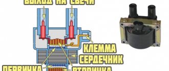
The coil is a pulse step-up transformer. It is she who ensures the conversion of low voltage, which is supplied to it from the battery or generator, into high voltage pulses.
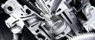
Thanks to these impulses, a spark jumps between the electrodes of the spark plug, which ignites the working mixture in the cylinders. Like any transformer, the coil consists of two windings (primary and secondary), a magnetic circuit and a housing.
The module is structurally somewhat more complex and includes two coils and a switch, but its operating principle is identical to the coil.
Selecting a multimeter
As a rule, in specialized services the device model MAS 838 is often found. It has the ability to measure a regular microcurrent of 200 µA. The display is backlit, so when carrying out this process in an unlit garage, you do not need to use a flashlight.
To run the process itself, specific accuracy is not required. Therefore, there is no point in purchasing an expensive model. It’s better to just buy the basic package, which is included in all standard devices.
Principle of operation
The operation of the ignition coil is based on the principle of operation of a step-up transformer, when a small voltage of 12 V is converted into several thousand volts.
Voltage conversion occurs thanks to two windings - primary and secondary, which were mentioned above. In the first, a decreased U is created, in the second, an increased one.
Depending on the type of device, the location of the windings and their design differ.
Principle of operation:
- The breaker closes the electrical circuit and voltage is supplied to the primary winding. Due to this, a magnetic field is generated in the coil.
- After opening the circuit, the magnetic field disappears, but passing through the secondary winding it generates a high voltage in it.
The operating principle of the ignition coil is clearly presented in the video.
Coil types:
- Regular.
- Individual.
- Two-terminal.
Regular ignition coil
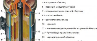
Here the primary winding is a metal core (to increase the magnetic field) around which 150 turns of thin insulated copper wire are wound, the ends of which are brought out to the housing.
The secondary high voltage winding is a thin insulated copper wire wound around a metal core with up to 50,000 turns.
The second winding is connected to the first by negative wires. The positive wire of the high voltage winding is brought out to the cover and connected to a special terminal.
Some models of ignition coils contain transformer oil as an insulator and for cooling purposes.
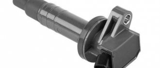
Custom ignition coil
Their design is more complex than conventional coils; they are installed on engines with electronic injection.
Structurally, they also have two windings, which differ from each other not only in the number of turns and wire thickness, but also in the reverse order of winding.
So in the primary winding the core is located as usual inside, and in the secondary winding outside. Also in the secondary winding, in order to cut off very high voltage, a diode is provided.
Also, thanks to special design solutions, it became possible to supply high U not to the distributor, as is the case with a conventional coil, but directly to the spark plugs.
Two-pin
Such an ignition coil immediately supplies voltage to the spark plugs of two cylinders, i.e. on a four-cylinder engine there will be two of them and they will be combined into one block, which is essentially a four-terminal coil.
Causes of malfunctions
Ignition coils are reliable devices and the main reasons for their failure include: insulation breakdown, limiting service life.
Below we list other reasons why a device may fail.
| 1. Aging and mechanical damage. | During operation, the materials from which the ignition coil is made lose their strength, begin to crack and collapse, and various liquids (oil, antifreeze, etc.) can affect the device, which negatively affects its service life. There is only one solution - replacement. |
| 2. Damage or oxidation of the contact connection. | Penetration of moisture under the hood, a humid climate, after fording, improper washing of the engine or car, all this can affect the condition of the contacts and their rapid oxidation. |
| 3. Vibrations. | Individual ignition coils of electronic injection vehicles are very sensitive to vibrations. For example, if the motor is tripping, or one of its supports is out of order, it vibrates strongly. Also, very bad roads, which are not uncommon here, can cause severe shaking and affect the position of the reels. |
| 4. Overheating. | The same applies to individual coils, which are located near the cylinder head, where the temperature is highest. In the intended temperature conditions of the engine operation, nothing will happen, but if, as a result of poor quality coolant or for other reasons, the engine overheats, this will negatively affect the ignition coil as a whole. |
Signs of breakdown
The reel has a reliable design and its service life is significant. And yet this element can also fail.
The main signs that the ignition coil is not working properly are:
- Inability to start the power plant;
- The inscription “Check Engine” appears on the dashboard (on cars with an ECU), and when scanning the system, code P0363 is displayed, indicating a malfunction of the ignition module (on modern injection cars);
- Decrease in power unit performance;
- Misfires, which causes the engine to “trouble” (with time the problem becomes more pronounced);
- Dips when reaching certain crankshaft speeds.
It should be noted that these malfunctions are also typical for other elements of the ignition system, for example spark plugs, so before you “sin” the coil, you should check the entire circuit coming from it.
Finding the origin of the problem
First you need to check the performance of the spark plugs, and this check may indirectly indicate a coil malfunction.
To check, you just need to unscrew the spark plugs, insert them into the tips of the high voltage wires, massage them and turn the crankshaft several times with the starter. In this case, you should look at the spark that forms between the electrodes.
If it is discovered that a spark plug is not working correctly and the spark in it is formed intermittently, it should be replaced and a known good one installed in its place.
If a working spark plug works intermittently, check the high voltage wire.
If the interruptions persist even when the wire is replaced, then in carburetor cars the distributor is inspected next, and only then the coil.
In injection cars equipped with a module, there is no such distributor, so you can immediately start checking the module.
Checking these elements will not be particularly difficult, and the only equipment you will need is a multimeter with the ability to operate in ohmmeter mode, with a measurement range of up to 200 MOhm.
To make it more clear, let’s look at how these ignition elements are checked on different cars.
Diagnostics of machines with distributor
Checking the ignition coil on any car begins with a visual inspection:
- Make sure that the converter housing does not have cracks where oil is leaking.
- Look for signs of burning on the transformer - black spots or the smell of overheated insulation.
- Check the low and high voltage supply terminals.
Further diagnostics are relatively simple: you need to make sure that voltage is present in the circuits before and after the coil. To do this, you need to catch the moment of spark formation - rotate the crankshaft in any convenient way and set the piston of the first cylinder to top dead center. Then follow the instructions:
- Unscrew the low-voltage wire from the converter and remove the distributor cover.
- Turn on the ignition, bring the wire to the ground of the car and turn the distributor slider, causing the contacts to open (or the Hall sensor to operate).
- If a small spark jumps between the contact and the body part, then voltage is applied to the coil.
- Screw the contact into place and remove the high-voltage wire from the spark plug of the first cylinder.
- Lean it against the body at a distance of 1–3 mm and repeat the operation. On a working coil, a powerful spark will jump between the conductor and ground.
Advice. It is extremely undesirable to hold a high-voltage wire with your bare hands during the inspection process. Even cloth gloves will not save you from electric shock, so it is better to fix the contact with improvised means and press down with a heavy object.
If a spark does not appear at the output, you need to ring the ignition coil with a multimeter or other device with a resistance measurement function. The verification algorithm is described below.
Basic Verification Approach
Since the windings play a key role in the operation of ignition coils, the first thing that needs to be checked, regardless of the type of device, is their resistance.
Thus, the resistance indicators of the primary winding can vary according to different data:
- from 0.6 to 4 Ohm;
- from 0.5 to 3.5 Ohm.
Secondary:
- from 6 to 15 kOhm;
- from 3 to 11 kOhm.
The indications are different because they can be different for each car model, so it is important to study the documentation for the car and the technical characteristics of the coil itself.
It is also important to understand that for each type of coil, indicators such as the inductance of the primary winding, the resistance of both windings, energy, duration and spark current may differ.
Measurements are performed with a multimeter or a regular ohmmeter.
If there is a strong deviation from the standard data, the ignition coil is most likely damaged. But there is no need to rush to change it; there are other ways to check.
Checking the coil for VAZ 2101-2110
First, let's look at the sequence of checks on VAZ cars. Moreover, checking the carburetor for VAZ-2101 and VAZ-2110 is no different, the only difference is in the readings.
Next is the verification process itself:
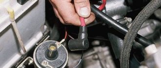
- It is better to test the coil when it is removed from the car. Before starting removal, disconnect the negative terminal from the battery. From the coil we disconnect the wires from the side terminals, as well as the central wire. It is better to mark the wires from the side terminals so that they are not confused during installation.
- Loosen the coil fastening and remove it. Before checking with a multimeter, we clean it from dust and dirt, especially paying attention to the terminals. Then we inspect it for external damage. If there are any, further checking is pointless; it is better to replace it immediately;
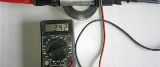
- Checking the primary winding. To do this, switch the multimeter to ohmmeter mode and connect its probes to the side terminals. Different types of coils were used on different VAZ models, so you need to know which resistance readings are correct for them. So, for the B-117A model, used on classical models (VAZ-2101-2107), the resistance of the primary winding is 3.07-3.5 Ohms. And on classic models with a contactless system, coils marked 27.3705 are used; this parameter is 0.4-0.5 Ohm. On VAZ-2108-21099 cars, as well as VAZ-2110 carburetor, models with numbers are used - 3122.3705 and 8352.12. For the first of them, the resistance of the primary winding is considered normal in the range of 0.39-0.47 Ohms, and for the second - 0.37-047 Ohms;
- Next, the secondary winding is checked. To do this, switch the multimeter to the kOhm measurement mode, leave one of its probes on the side terminal, and connect the second to the central terminal. For a working B-117A coil, the resistance of the secondary winding should be 7.4-9.2 kOhm. For model 27.3705 this parameter should be around 5.0 kOhm, for 3122.3705 - 0.4 kOhm, and for 8352.12 - 1.0 kOhm;
- The last thing to check is the insulation resistance. To measure this parameter, switch the multimeter to measurement mode in MOhm. To measure, we connect one probe to the coil body, and connect the second to each terminal in turn. When measuring this parameter on all specified models, the multimeter should show at least 50 MOhm;
- If any of the parameters does not match the specified values, then the coil is faulty and must be replaced.
A little theory.
On the “seven”, as a rule, contact ignition systems of the B-117 A type are used. The coil itself is located in the engine compartment and is attached to the left mudguard with two studs. Also found on the VAZ 2107 are non-contact ignition systems (BSZ), in this case, coils of type 27.3705 are used, oil-filled with an open magnetic circuit, as well as type 3122.3705 dry coils with a closed magnetic circuit.
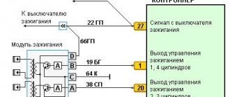
Testing the ignition module on a VAZ-2110 injector
On injection cars, for example, VAZ-2110, the module check is performed slightly differently.
The check sequence is as follows:
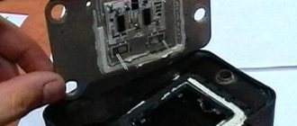
- We inspect the module for damage. Even small cracks can cause a module to fail, if not now, then in the near future. Therefore, such a module does not need to be checked, but replaced immediately.
- Disconnect the block of wires going to the module. First, check the voltage supply to the module. To do this, switch the multimeter to voltmeter mode, connect one of its probes to terminal “A” (the letters are stamped on the block), and the second to “ground” and turn on the ignition. If the wiring is good, the voltmeter should show 12 V or close to it.
- Then we take a 12 V test light and connect it to terminals “A” and “B” on the block. Then we turn on the starter and look at the “control”; it should blink when the starter is running.
- We switch the multimeter to ohmmeter mode with the measurement parameter in kOhm and measure the resistance of the secondary winding of the coil at the paired terminals. To do this, we connect one probe to the terminal that supplies an impulse to cylinder 1, and the second to the terminal of cylinder 4. A working module should have a resistance of about 5,4
kOhm - We take another measurement, but now on terminals 2 and 3 of cylinders. The readings at these terminals should be normal. A strong discrepancy in resistance at paired terminals indicates a module malfunction and the need for repair or replacement.
Conclusion
Checking the health of the coil is a fairly simple task if you have some experience and some equipment. The simplest and most effective way for home use is to check the resistance of the coil windings using a multimeter. To improve convenience during operation, the coil should be removed from the machine.
If the coil turns out to be faulty, it is better to replace it with a new one. Repair, namely rewinding the windings, is a very expensive, time-consuming and thankless task. It is much easier and faster to buy and install a new one.