Any car with a manual transmission needs to have its clutch replaced regularly. Replacing the clutch yourself is not particularly difficult if you have the necessary equipment and you know the procedure. The mileage of the disc is 70–150 thousand kilometers and depends on the operating conditions of the vehicle. Other clutch parts are changed as needed. After reading the article, you will learn how to change the clutch without going to a car service center.
Equipment and tools required for work
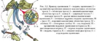
Clutch alignment guide
To work you will need:
- pit, overpass, lift or jack;
- a set of open-end and socket wrenches;
- mount;
- winch;
- input shaft of the gearbox (manual transmission) or a special mandrel corresponding to the type of gearbox;
- brake fluid (for vehicles with a hydraulic clutch);
- extension cord with carrying lamp;
- assistant.
Clutch replacement
Complete replacement of the clutch kit involves the following procedure:
- removal and installation of manual transmission;
- replacement:
- disk;
- baskets;
- master and slave cylinders (if any);
- cable;
- release bearing.
Removing and installing the box
Technologies for removing and installing manual transmissions on cars with rear-wheel drive and front-wheel drive are different. On rear-wheel drive vehicles, it is necessary to disconnect the clutch connecting the manual transmission to the driveshaft. On front-wheel drive vehicles, you will need to remove the drive shafts and insert plugs in their place. After this, disconnect the cables or links of the gear selection device, unscrew the fastening nuts, then remove the gearbox input shaft from the bearing in the engine flywheel.
Be sure to check the condition of the gear selector seal. Oil stains in the area of the rod indicate oil seal wear.
When installing, it is necessary to rotate the box shaft so that it fits into the flywheel splines. When removing or installing a manual transmission on vehicles with all-wheel drive or a large engine capacity, use a winch. After installing the manual transmission on the car, it is necessary to adjust the length of the rod that presses the fork.
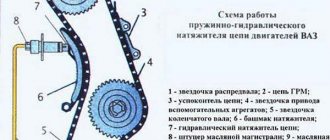
The principle of operation of the clutch in a car
This mechanism in a car is needed for more uniform gear shifting, reducing torsional vibrations, as well as temporarily disconnecting it from the engine gear. Components: drive and mechanism.
To supply force to any mechanism in the car, the drive mechanism comes into operation. Any mechanism in a car is equipped with a drive; its structure has its own specifics and operating features.
The shutdown drive, based on the hydraulic principle, has elements such as pedals, cylinders, a power plug, a pressure bearing, and a pipeline.
The mechanism transmits torque through the entry of friction force. Thanks to it, the engine and gearbox are temporarily separated, followed by their gradual reunification.Its components are a crankcase and a casing, a drive disk, a pressure disk together with springs, and a driven disk with wear-resistant linings.
Considering the video of replacing the mechanism yourself, the question arises of how to do it yourself.
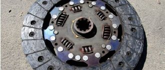
Replacing the disk and basket
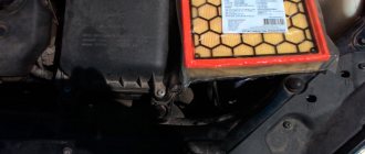
Replacing the clutch disc is done as follows. Unscrew the basket mounting bolts, then remove all parts from the flywheel. There should be no traces of oil on the flywheel or driven disk surface. If there are marks, it is necessary to check the condition of the gearbox oil seal, otherwise the oil leak will continue, which will reduce the service life of the disc. Droplets of oil falling on the surface of the lining or driven disc damage them. If the condition of the oil seal is unsatisfactory, replace it. If the surface of the driven disk is covered with deep scratches or cracks, change the basket.
Wipe with a rag, then degrease the surface of the flywheel and the basket driven disk with gasoline. Insert the disc into the basket, then slide both parts onto the manual transmission input shaft or mandrel, and then insert into the hole in the flywheel. When the mandrel reaches the stop, guide the parts along it to the flywheel and screw the basket with standard bolts. Pull out and then reinsert the mandrel a few times to make sure the disc is seated straight. If everything is normal, insert the mandrel and tighten the bolts with a force of 2.5–3.5 kgf-m. More precisely, the force is indicated in the repair instructions for your machine. This completes the replacement of the clutch disc. Replacing the clutch basket is done in the same way. The maximum mileage of the basket is 150–250 thousand kilometers and depends on many factors.
Remember, replacing a clutch disc is a responsible operation, so do not perform it in a hurry or while intoxicated.
Vibration after replacing the clutch appears due to improper alignment of the disc or weak tension of the basket. If this happens, you will need to remove and reinstall the drive and cage.
Re-riveting driven disk linings
To replace worn friction linings of driven disks, you must:
- drill or cut off the rivets with a pointed chisel and remove the linings; Drill out the rivets carefully so as not to damage the holes in the disk;
- place a new lining on the disk, mark the centers of the holes, drill holes and countersink them so that the rivet heads are 0.5 mm from the surface of the lining;
- select brass or copper rivets according to the diameter of the disk holes and the thickness of the assembled disk with linings so that the length of the protruding part of the rivet is approximately equal to 0.7 of its diameter;
- rivet the linings to the disk manually or using a bench tool with frequent and strong blows (so that the heads of the rivets on both sides are buried 0.5 mm from the surface of the linings).
Rice. Bench device for riveting clutch disc linings.
After riveting, the surfaces of the linings are cleaned with a file or emery stone and the disc is checked for runout in the centers on the mandrel. The runout from the short end of the disk hub at a radius of 120-150 mm should not exceed 0.5 mm. If the runout is greater than the specified value, the disc is straightened on the plate with hammer blows.
The linings of the driven clutch disc (for GAZ-51 and M-20 Pobeda cars) are riveted to leaf springs located around the circumference of the disc. In this case, each overlay is riveted separately.
Replacing cylinders
- Replacing the clutch master cylinder is necessary if installing new O-rings does not improve system performance.
- Replacing the clutch slave cylinder is necessary if brake fluid continues to leak even after installing new seals.
b - working cylinder pusher
To remove the slave cylinder, remove the spring that returns the fork when the pedal is released. Next, remove the 2 nuts that secure the slave cylinder to the transmission housing. Holding the working cylinder suspended, unscrew the rubber hose that fits it.
To avoid brake fluid leakage, immediately screw the new slave cylinder to the hose. To remove the master cylinder, pump out all the fluid from the reservoir. Unscrew the fitting with the copper tube that goes into the cylinder and close it with a rubber plug to prevent brake fluid from leaking out. Move the tube to the side so it is out of the way, then unscrew the two nuts securing the master cylinder to the car body. Pull towards you and unclip the joint to which the pedal is connected. Pull out the pin and disconnect the cylinder from the pedal. Install the master and slave cylinders in the reverse order. Don't forget to adjust the length of the rod that pushes the clutch fork.
Master cylinder
After installing new cylinders, pour new brake fluid into the reservoir and be sure to bleed the clutch. To do this, put a rubber tube on the valve and lower it into a transparent container, pour brake fluid into it, then ask him to smoothly press/release the pedal 4 times. After this, ask to press the pedal again and not let go without your command. When the assistant presses the pedal for the fifth time, unscrew the valve to drain the fluid. Then tighten the valve, and then ask an assistant to release the pedal. It is necessary to pump the clutch until you are sure that the fluid comes out without air. Add brake fluid to the reservoir in a timely manner so that the cylinder does not suck air. If the brake fluid level drops too much, re-bleeding will be required.
Brief summary
Replacing the fastening mechanism on cars is a labor-intensive process, but it can be done independently.
To do this, you need a specially equipped place, tools, as well as knowledge of the features of installing parts. We discussed how to make the clutch mechanism of some cars in this article.
Replacing the cable
The cable replaced the hydraulic clutch. Higher reliability, low maintenance requirements and low price made the cable very popular. The cable must be changed if the mileage has exceeded 150 thousand kilometers or more than 10 years have passed since the previous replacement. Replacing the clutch cable is not difficult even for an inexperienced driver. Release the fork from the return spring, then remove the cable. After this, unpin the connection and remove the cable from the pedal. Pull out the pin, then remove the old cable through the interior. Install the new cable in the same way. This completes the replacement of the clutch cable. The cable must be changed if even slight damage is found on it. If this is not done, the cable will break while driving, making it impossible to change gears.
Replacing the release bearing
The mileage of the release bearing should not exceed 150 thousand kilometers. In addition, replacement of the release bearing will be required if the gears begin to shift indistinctly or if there is noise when pressing the clutch pedal. The procedure for replacing the release bearing is described in detail in the article replacing the release bearing.
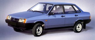
Which VAZ 2110 clutch is better?
This question is asked by every VAZ 2110 owner when he is faced with the need to choose a mechanism. Below are the results of reviews of devices by experts in the Russian automotive market. It is also worth noting that during the research process, the most popular manufacturers among domestic motorists were considered.
- Krafttek. The kit does not include a bearing, so you will have to buy it additionally, and there is also no quality mark. The basket is equipped with 18 petals and the driven shaft (Y 3200A B0206) has 4 springs. This mechanism is recommended for use in the VAZ 2110.
- German manufacturer Luke (Lamellen und Kupplungsbau). The set is complete, you don't have to buy anything else. The packaging contains the MT14 quality mark. In addition, the driven shaft is marked with markings for proper installation. The element basket also has 18 petals, and the driven shaft is equipped with 6 springs. It is also worth noting that the basket side is marked on the shaft.
- Valeo, manufacturer France. A complete set, you don’t have to buy anything extra. Moreover, this clutch comes with a lubricating fluid for the mechanism, as well as a CD with installation instructions. There are 18 petals in the basket.
- Russian. The kit does not include driven and pressure pulleys, as well as a release bearing. Nevertheless, the product received the AYA70 quality mark. There are 12 petals in the basket, and 6 springs on the driven shaft. The product has been approved for installation in the VAZ 2110.
- Pilenga, country of origin unknown. The kit does not include a pressure pulley and a release bearing, so if you decide to replace the mechanism completely, then these components will need to be purchased. There are 18 petals in the basket. There are 8 springs on the driven shaft. There are no approval marks on the packaging.
Actually, any of the clutches listed above is suitable for VAZ 2110 cars. For example, the Luke cannot produce maximum torque, so engine power will be reduced when driving. Krafttek is a fairly reliable, time-tested mechanism, although you will have to purchase some additional elements to install it.
It is worth noting that this unit also has many positive reviews on the Internet from other motorists. But keep in mind that if the package for this mechanism does not contain lubricating fluid and a CD with installation instructions, then this is a fake. Having installed such a device, be prepared for the fact that it may fail after 5 thousand kilometers.
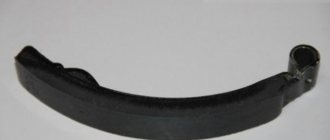
How to replace the plug
The clutch drive fork is a kind of lever that retracts the pressure plate and disengages the clutch. In hydraulic drive gearboxes, such a mechanism, consisting of a pair of legs, a metal rod and a lever, is quite rare.
Replacement instructions
Along with other automotive mechanisms, the clutch fork can fail due to wear or cracking. Replacement steps:
- removing the return spring;
- bending the cylinder and removing the fork axis;
- removal of special protective coating;
- removing the plug.
At the final stage of replacement, a new mechanism is installed. For this purpose, the end of the spring is inserted into the hatch and smoothly moves towards the end past the bearing coupling and springs to a special recess with petals.
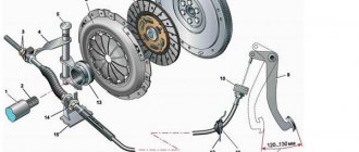
CLUTCH PARTS - REMOVAL AND INSTALLATION
To perform the work, you will need a special mandrel for centering the driven disk or the transmission input shaft.
Removal
1. Place the car on an inspection hole or overpass (see p. 21. “Preparing the car for maintenance and repair”).
2. Disconnect the starter from the clutch housing. We move the starter forward, removing it from the studs (see p. 186. “Starter - removal and installation”).
3. Remove the gearbox (see p. 100, “Gearbox - removal and installation”).
4. Disconnect the exhaust pipe from the exhaust manifold (see p. 96, “Exhaust system - replacement”) and move it to the side.
Note
| 10. Remove the cylinder. |
If disconnecting the exhaust pipe from the exhaust manifold is difficult, then disconnect the main muffler from the body and remove
rear of the engine§
down together with the "start" system (see p. 96, * Exhaust systems - replacement).
5. Remove the clutch slave cylinder from the hole in the crankcase housing without disconnecting the detachable pipeline (see p. 101, “Clutch release hydraulic cylinder - removal and fatigue”).
6. Use a 10 mm wrench to open the screws"
| 8. Sliding it off the studs, removing the clutch housing. |
We eat three bolts securing the dirt shield and remove it.
7. Using a 17-point socket wrench with an extension and cardan, unscrew the four bolts that secure the clutch housing to the cylinder block.
9. If it is not planned to replace the basket, then we apply two aligned marks on the center punch and the flywheel.
Attention!
When performing the following operation, to avoid
deformation of the clutch casing, unscrew the bolts sequentially, no more than one turn per pass.
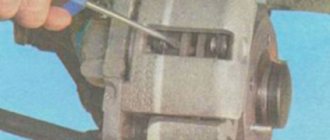
10. If necessary, holding the flywheel from turning with a mounting blade inserted between the teeth of the flywheel crown, use a 12 mm socket wrench to unscrew the six bolts securing the basket to the flywheel.
11. Remove the basket and the driven clutch disk located under it.
12. To remove the clutch fork, use a slotted screwdriver with a wide blade to unscrew the two screws securing the fork to the crankcase.
Installation
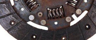
Before installing the clutch parts, check their condition. On the working surfaces of the flywheel and pressure plate, deep grooves A (marks left by the rivet heads of the driven disk linings), burn marks and cracks are unacceptable.
The friction linings of the driven disk should not have cracks, chips, warping or severe wear. The heads of rivets B must be recessed below the level of the contact surfaces of the linings.
The driven disk hub should move smoothly along the splines of the input shaft. The working surface of the release bearing must be smooth, without damage, and the minimum permissible height of protrusion from the cage is 5 mm.
| 14. Having turned the two clamps 180°, remove the release bearing from the coil. |
If there is oil in the clutch housing, we determine the cause of its appearance. In this case.
The crankshaft oil seals (see p. 62, “Crankshaft rear oil seal—replacement”) or the transmission input shaft (see p. 121, “Input shaft oil seal—replacement”) may be damaged or worn.
We replace faulty and damaged parts. It is advisable to install new bolts securing the basket to the flywheel.
1. Wipe the working surfaces of the disks, flywheel and input shaft with a rag moistened with white spirit.
2. Apply a thin layer of CV joint-4 grease or similar to the smooth and splined surfaces of the input shaft.
3. Having inserted the driven disk into the clutch housing, orienting it with the protruding part of the hub towards the pressure plate, install the housing on the three flywheel locating pins according to the previously applied marks. Install the casing mounting bolts without completely tightening them.
4. Insert the input shaft or mandrel into the spigot hole of the driven disk hub and at the same time into the inner race of the input shaft bearing, centering the driven disk.
5. Evenly tighten the bolts securing the clutch basket to the flywheel, turning them no more than one turn per pass. After tightening the bolts, the mandrel should be freely removed from the driven disk.
6. Further installation of all removed parts is carried out in reverse order.
7. Adjust the free play of the working cylinder pusher (see p. 100, “Hydraulic clutch release - adjustment”).
The gearbox is designed to change the magnitude and direction of the torque given by the engine to the mediating wheels
| 9.2 1 |
| 92.2 |
The vehicle is equipped with a 412-1700010-01 gearbox with four forward gears and one reverse gear. The gearbox consists of a cast iron crankcase with an extension cast from an aluminum alloy attached to it with heel bolts.
0,9
| REFERENCE DATA Table 9.2.1 Gearbox ratios |
| Broadcast | Gear ratio |
| 111 rv per neck stroke | 3,494 2.042 1,334 1,00 3,388 |
| Table 9.2.2 |
| Refill containers and oil used |
| Volume of gearbox housing, l Transmission oil group according to API K IICC vi 4KOSGI according to SAI |
GL-4
| DESIGN DESCRIPTION |
| Gearbox: 1 selective lever (408-1703096). 2 thrust release spring (412-1703079-0′) 3 pyreilute lever (408-1702053); 4 filler plug (366748) 5 bokshych cover (408-1702013-10). c — crankcase (408-1701015-10). 7 - pnrvichmmi fell (2140-1701030) 8 speedometer drive gearbox (407-3802810-G1); 0 crankcase extension (2140 1701200 10). 10 secondary input (408-1701105) |
75W90. H0W90. 85W90
The gearbox housing is secured with four bolts to the clutch carrier. The following are installed on the gearbox housing: primary and secondary shafts, gears, synchronizers. Intermediate shaft I and part™ of the gear shift drive. The holes in the side walls of the crankcase are closed with covers. In the left cover and in the bottom of the crankcase there are filler and drain holes, closed with plugs with conical threads
Extension with the middle part of the pi gay to the rear cross member of the power unit. On the right on udts. The speedometer gearbox is attached to the jacket.
The input shaft is double-horned! Its supports are ball bearings, one of which is pressed in the end seat of the crankshaft, and the other in the front wall of the crankcase. A slot is cut into the neck of the primary gear for installing the driven clutch disc. At the rear of the shaft there is a gear block made of; steren and gear ring of the IVth pers.
The secondary shaft is three-bearing* It rests on the front part! roller bearing located 1 at the end of the primary shaft ' Middle support bearing I ball, installed in the front! 1 piece extension. The rear support of the yam are two steel bushings installed in the rear of the yam thread, on which it rests through the driveshaft fork.
Gears with synchronizers and a speedometer drive gear are installed on the secondary shaft. A cardazz fork is put on the rear splined part. Clutches and synchronizer hubs are sorted by mounting diameters at the bottom of the group and marked with yellow and blue paint. The reverse gear is made as a single block with the synchronizer clutch for 1st and 11th gears.
| 9.2. TRANSMISSION |
The intermediate fork gear block is mounted on two roller bearings on the axle. pressed into the front and rear walls of the crankcase. The axial forces of the gear block are absorbed by the front and rear thrust washers. The gearbox housings and gear blocks are divided into two size groups, depending on the distance between the thrust bosses 31 of the housing 163.50-163.58 mm (the housing is marked with blue paint) or 163.59-163.66 mm (the housing is marked with yellow paint) and length of the gear block together with the front thrust washer 161.87 161.94 mm (yellow marking) or 161.95-162.03 mm (blue marking) selected correspond!! rear thrust washer
The thrust washer is made in three sizes: 1.40; 1.49 and 1.58 mm (blue, black and yellow markings). If the markings of the block and crankcase coincide, the rear washer is installed in the corresponding color; if not, then a washer with a black mark is installed. In this case, the axial clearance of the gear block in the crankcase should be in the range of 0.08 -0.23 mm.
The two forks for engaging the forward gears are moved along a rod installed with its ends in the holes in the crankcase walls. In the engaged gear position and in the neutral position, the forks are fixed with reinforced balls and retainers. The forks are driven by a gear shift mechanism assembled on the left side cover of the box. and connected by two rods
mi with a gearbox control mechanism. The reverse gear fork is installed on a shaft secured to the left cover and in the crankcase boss hole. The fork will mix the reverse idler gear, engaging it with the gears on the output shaft and the idler shaft gear block. The reverse intermediate gear is mounted on a bronze bushing, the axis of which is pressed into the crankcase walls.
The gearbox control mechanism with the gear shift lever is located in the opening in the tunnel no ia of the body and is secured with four bolts.
| 15 16 1718 19
|
| Parts of the gearbox 412-1700010-01: 1 — thrust ring of the bearing (401-1701054 3 pcs.), 2 — thrust washer for the front gear block (401-1701060), 3 — bearing rollers of the gear block (401-1701052. 2×23 PC.); 4 — intermediate shaft gear block (408-1701050-01); 5 — lll gear gear (2140-1701131); c — input shaft (2140-1701030); 7 - rear bearing of the input shaft (412-1701032-01 (6- 50206KSh 1) 8 - synchronizer blocking ring (2140-1701164-100.4 pcs.); 9 - nut (408-1701157); 10 - lock washer (408-1701159 -6); 11 spring washer (408-1701166-B); 12 — rollers of the front bearing of the secondary shaft (401-1701180. 15 pcs.). 13 — synchronizer clutch of the 1st and 4th gears with hub assembly (408 -1701175-10/ 408-1701154-01); 14 — bushing (408-1701128B1, 3 pcs.); 15 — shift fork for 1st and 4th gears (408-1702028-02); 16 shift fork 1- 1st and 11th gears (408-1702022-02); 17—spacer washer (408-1701115. 2 pcs.), 18—reverse gear with hub assembly (408-1701140-10/408-1701144-01) ; 19 — gear shift fork rod (408-1702061-01); 20 — lock ball (263011); 21 — lock spring (400-1702022); 22 — secondary shaft (408-1701105); 23 — speedometer drive gear (402 -3802833-A). 27 — reverse fork (408-1702094-B); 28 — reverse intermediate gear (408-1701082); 29 — 11th gear gear (2140-1701127); 30 — rear thrust washer of the gear block (408-1701062) 31 — axis of the gear block (2140-1701072); 32 — spacer tube (408-1701058) |
On Moskvich-412 cars of early production, a gearbox 412-1″00010-B was installed, used with a control mechanism mounted on the steering column, and a gearbox 412-1700010, used with a floor-mounted control mechanism. The 412-1700010 gearbox assembly is completely interchangeable with 412- 1700010-01. Structurally, it mainly differs in the location of the filler hole on top of the crankcase and the presence of an oil level indicator. To repair boxes of early modifications, parts from box 412-1700010-01 must be used in kits, replacing a group of parts. Parts, catalog numbers, which begin with the numbers 408 of all boxes, are completely interchangeable.
The 412-1700010-01 gearbox differs from the 2140-1700010-10 gearbox in the gear ratio of the speedometer drive gearbox (407-3802810-GI/2140-3802810-10). When replacing one gearbox with another, it is necessary to change the speedometer drive gear accordingly.
I?Mkl GEARBOX - CHECKING TECHNICAL CONDITION
1. Place the car on an inspection hole or overpass (see p. 21, “Preparing the car for maintenance and repair”).
2. Using the gear shift lever, make sure that all gears are engaged easily, without jamming. The action of the gear shift clamps should be noticeable on the lever (there should be a slight temporary resistance when turning the gear on and off). The lever strokes must be sufficient to engage gears. If the gears are not engaged clearly and easily, the adjustment of the control mechanism may be broken (see page 10. 'Gearbox control mechanism - adjustment') or the gear shift mechanism is faulty (see page 111, 'Gearbox - disassembly and assembly") If there is significant play in the lever, we replace the control mechanism assembly or replace the plastic bushings with it (see p. 109, “Gearbox control mechanism bushings - replacement”).
3. Engage reverse gear (with the ignition on).
| 5 6 7 8 |
Gearbox control mechanism:
1 — lower selective lever (408-1703096); 2 - cracker (407-1703152) with regu; MU suspension nuts. 3 — lower shift lever (408-1702053); 4 ta • j gear shift (412-1703134); 5 — reverse light switch (2140-3716630/VK418); 6 — control mechanism housing (412-1703221); 7 — gear shift lever (412-1703084); 8 — upper lever guide (412-1703070; 9 — upper selective lever (412-1703055); 10 — upper shift lever (412-1703028) 11 — selective rod (412-1703164-01); 12 — release rod spring (412 -1703079-01); 13 — reverse gear stop (408-1702063)
To enhance the work, tarnish
There is a special syringe for injection and a container for collecting orpjfo. tan hoi o oil with a volume of not less than 2 liters, new transmission (see p. 104, “Reference data
Execution Sequence
1. We install the car .1 inspection hole or overpass (p* p. 21, “Preparation of the vehicle for maintenance and repair”),
2. Using a steel brush and vetch, we clean the filler and drain plugs from dirt, as well as* the surface of the crankcase near the samples*
3. Using a 9 mm square wrench, unscrew the hall plug.
make sure that the reverse lights come on. If necessary, adjust the position of the light switch by selecting shims or replace the switch (see page 107, “Reversing light switch - removal and installation, checking”).
4. From below the car we inspect the clutch and gearbox housings and the gearbox extension. On their surfaces, cracks and kinks, and signs of significant leakage of the sweep are unacceptable.
5. Check the tightness of the bolts securing the gearbox housing to the clutch housing, bolts securing the extension cord and covers. The rear powertrain support bracket must be securely attached to the extension and rear engine mount cross member, and the cross member to the underbody.
6. Unscrew the filler plug (see p. 106, “Gearbox - replacing the pump”) with a screwdriver or other suitable object. check the oil level, which should reach the bottom edge of the hole. If necessary, add oil.
7. With the engine turned on and the gear shift lever in neutral, there should be no noise or knocking in the gearbox, and gear shifting should occur without grinding. There should be no noise or knocking even when the gearbox is operating under load.
8. To check the condition of the internal parts, drain the oil from the crankcase (see page 106, “Gearbox - oil change”). The presence of metal particles in it indicates severe wear or damage to the parts.
CSJ2J GEARBOX - OIL CHANGE
We change the oil every 30 thousand. km (see page 23, “Periodic maintenance”), The oil should be changed immediately after the trip. Hot oil drains faster and more completely, along with wear products suspended in it.
4. Place a container under the drain hole.
5. Using a 9 mm square wrench, unscrew the drain plug.
6. Drain the oil into the prepared container.
7. Clean the drain plug and install it in place
Note
If the drained oil is dark in color and metal particles are clearly visible in it, it is recommended to flush the gearbox.
To do this, pour 0.9 mixtures of kerosene gear oil into the box in a 1:1 ratio and start
loosen the filler plug (see point 8). We put the gear in neutral and start the engine. After 3-5 minutes of idling the engine, turn it off, drain the flushing mixture, clean and tighten the drain plug
8. Fill the box with fresh transmission oil to the level of the lower edge of the filler hole (see page 104, “Reference data”) and tighten the plug.
REVERSE LIGHT SWITCH - REMOVAL AND INSTALLATION, CHECK
To do the job you will need a multimeter.
Execution Sequence
1. We prepare the car for work (see p. 21, “Preparing the car for maintenance and repair”).
2. Disconnect the wire from the negative terminal of the battery (see p. 179, “Battery - removal and installation”),
3. Inside the car, remove the floor tunnel cover by threading the gear shift lever through the hole in the cover.
4. Disconnect the wire from the switch terminals.
Between the switch housing and the housing of the gearbox control mechanism, adjusting shims A for the switch position are installed.
6. To check the switch, connect an ohmmeter to its terminals. When you press the ball, the resistance should tend to zero. Otherwise, replace the switch.
7 Installation of all removed parts is carried out in reverse order.
8. Engage reverse gear. In this case, the shift lever driver pin will press the switch ball. If the switch prevents the gear from being engaged. add an adjusting washer under it. Turn on the ignition and check the operation of the reversing lights. If the lights do not light, remove the washer (or replace it with a washer of smaller thickness).
QEX3 GEARBOX CONTROL MECHANISM - ADJUSTMENT
The position of the parts of the gearbox control mechanism is adjustable if the gears become difficult to engage, not clearly and easily enough, if the mechanism was removed for repair or replacement.
Execution Sequence
1. Place the car on an inspection hole or overpass (see p. 21, “Preparing the car for maintenance and repair”).
2. We clean the dirt from the bottom of the car and treat the rod joints and the threaded fastenings of the rods to the crackers with penetrating lubricant.
3. Remove the tip of the selective gear rod from the pin of the mechanism lever (see p. 108, “Gearbox control mechanism - removal and installation”).
4. Remove the floor tunnel cover (see above, “Reversing light switch - removal and installation, check”).
5. Having aligned the hole in the driver of the upper selective lever with the socket in the mechanism body, insert a rod with a diameter of 6 mm, blocking the driver (a drill can be used for this purpose).
6, using a 17 mm wrench, unscrew the nut securing the gear shift rod to the upper arm holder, holding the locknut with a wrench of the same size. so that the draft can mix freely in the hole of the cracker.
7 We check the inclusion of all gears of the box by switching its levers. If the gearbox mechanism works smoothly without jamming, set the lower gear shift lever to the positions for engaging the 3rd and 4th gears. In this position, cam A of the selective lever reaches the reverse gear stop B, but does not push it down.
8 In this case, hole A in the tip of the selective rod should be located exactly opposite finger B and be easy to put on it.
9. If the position of the stick and the hole do not coincide, we change the working length of the select rod by moving the block along the rod. To do this, use a 17 mm wrench to unscrew the nut securing the selective link to the block, holding the lock nut with the wrench same size.
10. Having established the required length, fix the cracker on the rod and connect the rod to the upper arm.
11. Without moving the lower lever from the position for engaging II, 1st and 4th gears, connect the gear shift rod to the upper lever.
Note
By changing the working length of the gear shift rod, you can set the tilt of the shift lever to be more convenient for the driver.
12 We take out the rod that blocks the leash of the upper selective lever.
13. Install all the removed parts in the correct sequence.