| Home Auto Electronics Ignition system for VAZ-2108 car |
Rice.
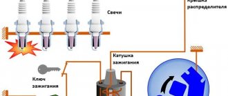
1. Functional diagram of the ignition system of the LADA VAZ-2108 car. The contactless ignition system of the VAZ-2108 car consists of a distributor sensor 40.3706, a switch 36.3734 and an ignition coil 27.3705. Features of the design and circuit solutions of this ignition system are:
- horizontal arrangement of the sensor-distributor shaft and its drive from the end of the engine camshaft;
- use of a microswitch based on the Hall effect as an engine crankshaft position sensor;
- the use in the switch of systems for regulating the period of energy accumulation in the ignition coil with limiting the current at low engine speeds, stabilizing the switched current when the supply voltage changes from 6 to 18 V, turning off the system when the ignition switch is on and the engine is not running (after 2-10 With).
The ignition system develops a voltage of up to 26 kV with a spark plug shunt resistance of Rsh = 1 MΩ and capacitance Csh = 50 μF, a spark discharge energy of 40-50 MJ with a discharge duration of 1.6-2.0 ms.
The rise rate of the high voltage pulse is 700 V/µs, which ensures reliable operation of the ignition system.
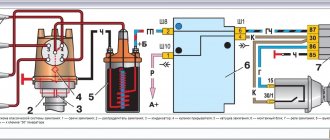
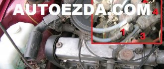
Rice. 2. Sensor-distributor 40.3706: 1 - housing; 2 - centrifugal regulator; 3 — rotor (curtain); 4 - sensor; 5 - slider; 6 - cover; 7 - coupling.
The distribution sensor 40.3706 (Fig. 2) consists of a centrifugal 2 and vacuum ignition timing regulator of a conventional design and a voltage pulse sensor 4 that controls the operation of the switch. The operation of the pulse sensor is based on the Hall effect. If a current passes through a semiconductor wafer, and the wafer is penetrated by a magnetic field, then a Hall emf appears on the faces of the wafer perpendicular to the current and magnetic flux. The magnetic field is created by permanent magnet 1 (Fig. 3), and the magnetic field is interrupted by rotor 2 with slots mounted on the distributor shaft. When the rotor slot passes near a permanent magnet, the force lines of its magnetic field penetrate the surface of the Hall element 3, and an emf appears at its output. Amplifier 4 amplifies the sensor signal, and through relay amplifier 5 the signal reaches the base of output transistor 6 and opens it. When a rotor tooth hits a magnet pole, its magnetic field is shielded, the Hall EMF disappears and the output transistor 6 closes. As a result, a square wave signal is removed from the collector of the output transistor, which is used in the switch to interrupt the current in the primary circuit of the ignition coil.
Rice. 3. Diagram of a contactless microswitch with a Hall element.
To eliminate the influence of fluctuations in network voltage and temperature on the output signal of the sensor, the sensor circuit has a stabilization unit 7. All elements of the circuit, in order to eliminate the influence of interference on its operation, are made in one microcircuit, structurally connected to the magnet and the magnetic system.
The functional diagram of the ignition system is shown in Fig. 1.
When the distributor shaft S2 (40.3706) rotates, a rectangular signal appears at the output of sensor D, the trailing edge of which corresponds to the moment of spark formation. The sensor signal is fed to the input of switch I (36.3734) and through the inverter AND of block II for normalizing the energy accumulation time is supplied to the input of integrator A1.2, the sawtooth output voltage of which is compared with the reference voltage Uop2 in comparator A1.3. If the integrator output voltage is greater than the reference voltage, then a positive voltage is generated at the comparator output (logical 1).
If the integrator output voltage is less than the reference voltage, then there is no voltage at the comparator output (logical 0). The signal from comparator A1.3 is fed to the output stage IV of the matching circuit I1, which controls the operation of the output transistor VT. When comparator A1.3 transitions from the logical 1 state to the logical 0 state, the coincidence circuit opens the output transistor VT and current I1 appears in the primary winding L1 of the ignition coil T (27.3705). When a logical 1 signal from the output of comparator A1.3 is received at the input of the coincidence circuit I1, the transistor VT closes and the current I1 disappears, and a high voltage appears in the secondary winding L2 of the ignition coil. The normalization of the flow time of the current I1 in the primary winding of the ignition coils is carried out by a delay in turning on the output transistor VT relative to the controlled signal of the sensor. The delay value depends on the difference between the maximum voltage on capacitor C1 and the reference voltage Uop2. The higher the engine crankshaft speed, the lower the voltage on capacitor C1 and, therefore, the energy accumulation time will decrease.
Ignition settings
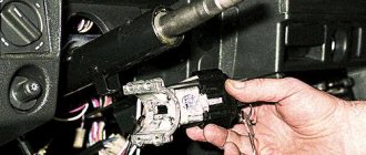
When setting up the ignition, you will need to do the most important thing - install the shafts according to the marks so that the gas distribution functions synchronously with the operation of the piston group. This is the first thing you should do before you start adjusting the ignition. It is worth noting that there should not be any particular difficulties during setup, especially on VAZ 2108-21099 cars. The thing is that the ignition distributor on the engines of these machines can only be installed in one position. Moreover, the ignition switch does not undergo any settings during this procedure, since it does not have any.
The distributor body rotates around its axis to make more precise adjustments. And this turns out to be enough. To accurately set the torque, you can use a simple circuit that uses a simple LED as an indicator. The Hall sensor is disconnected from the system, and positive power is supplied to its negative terminal. An LED is switched on between “+” and the signal LED, and a 2 kOhm resistance is connected in series with it to reduce the voltage. But the plus of the Hall sensor is connected to ground. Now all that remains is to slowly rotate the distributor housing. The moment when the diode lights up will be the desired one.
Troubleshooting Methods
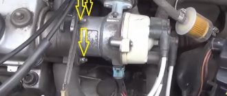
You can test the switch in road conditions. You should disconnect the wire that comes from pin 1 and connect a light bulb (12 volts) into the gap. When you crank the crankshaft, the light should come on periodically. This means that the VAZ 2108 switch is working properly.
You can check it differently: disconnect the wire from the distributor and insert a regular paper clip into the central contact. Connect the latter for a short time (1 second) to the distributor body. Place the high-voltage armored wire from the ignition coil on the brake master cylinder with a contact gap of 1 centimeter.
After these simple operations, turning on the ignition, a spark should appear. If the latter appears, the switch is working.
Why the engine may unexpectedly “start up” after rain, and what to do about it
The long-awaited summer greeted residents of the central region with rain and deep puddles. It rained so much that, they say, even the country estate of Prime Minister Mishustin was flooded. And what the private property of ordinary citizens had to endure is scary to think about. It wasn't just real estate that suffered from the weather: transport suffered just as much.
Moisture is generally the most dangerous enemy of a motor, but the problem in 2020 is not so much water hammer - such a puddle has yet to be found in the city - but the percentage of air/water, which over the past week in the capital has reached the level of an aquarium. It is clear that in such conditions the processes of oxidation and decay proceed much faster. However, the blues of a power unit from heavy rains do not always lie in rust, and some symptoms, localized at an early level, even allow everything to be solved with “little loss.”
The first step is to disassemble the air filter housing and carefully diagnose the condition of the filter element: if the canvas is wet or even damp, then the problem has been found. A wet filter allows air to pass through much worse, therefore the engine runs on lean fuel, abuses fuel and generally fails. The logic of further actions is clear: the casing itself must be dried, vacuumed from dust, and the filter must be replaced or, at worst, dried. If after all the measures described above the internal combustion engine’s well-being has not improved, you will have to roll up your sleeves.
The plug on the oil filler neck will tell you about the condition of the oil: if a white “sour cream-like” coating has formed on it, then water has gotten into the oil and you should speed up the replacement. Alas, today's engines are not ready, like their predecessors, to drive with such lubrication. If no emulsion is found, then the devil is in the candles and high-voltage wires. Let's start with the last ones.
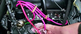
The wire running from the ignition coil to the spark plug should not crumble in your hands, be bent or damaged. It simply must look amazing and sparkle with novelty, because the speed and other characteristics of fuel ignition in the cylinder directly depend on it. You don’t need to be a rocket scientist to fully diagnose it. Any gap - chip, tear, scratch - indicates the need for replacement. The only equipment you need is your eyes.
If nothing like this is visually detected, wait until evening and ask a friend to start the car, first opening the hood and concentrating on the front side of the engine. Broken high-voltage wires will “generate” fireworks no worse than New Year’s
Source
Distributor slider VAZ 2109
Removal and installation
If the distributor fails, it can be repaired or replaced with a new one. It all depends on the specific failure.
The removal and installation procedure is as follows:
First you need to de-energize the car's electrical circuit by disconnecting the battery. Then you need to disconnect the wires from the switchgear. After this, also disconnect the vacuum tube going to the corrector. Next you need to find the cable holder that goes to the throttle actuator. This cable must be removed. Remove the bracket holding the wires, along with them and the pins. To do this you will need to unscrew the nut. Be careful. There is a washer under the nut, you can't lose it. After this, you need to mark the switchgear housing and the drive of the auxiliary elements. If you do not put a mark, then after further securing the mechanism in place you will have to reinstall and adjust the ignition. On the distributor body there is a socket to which the high-voltage wire harness is connected. The fasteners need to be compressed; to do this, remove the wires using a screwdriver. Then remove the rubber plug that is located in the clutch housing. Rotate the crankshaft by hand until the piston of the 1st cylinder reaches TDC. The mark on the flywheel in the hole should correspond to the center line on the housing scale. You can then unscrew the nuts that secure the manifold and remove it. As for further installation, it is carried out in the reverse order. When reinstalling the device, make sure that the valve shaft rotates so that the outer contact of the slide is opposite the terminal corresponding to cylinder 1 of the internal combustion engine. The terminal itself is located on the lid. During installation, combine the risks as we reported above. If you have difficulty installing the ignition, use this article.
Sorry, there are no surveys available at this time.
Purpose of distributor VAZ 2109
In any ignition system, contactless or contact, there are two circuits. high voltage and low voltage. Distributor, ignition distributor. It is a device that deals with both high voltage wiring and low voltage wiring. His main task. distribute high voltage between the spark plugs at the right time and in a certain order.
The distributor works as follows. High voltage is created in the ignition coil due to electromagnetic induction. It is connected via a high-voltage wire to the central contact of the distributor cap. The contact is in constant interaction with the slider, which distributes the current to four contacts corresponding to the spark plug in the cylinder. The slider constantly rotates and alternately closes the central contact with the spark plug contacts. Current is supplied to the spark plugs through high-voltage wires in the order determined by the cylinder sequence. 1-3-4-2. The slider is driven by a drive shaft, which is connected to the camshaft.
Ignition coil
Connection diagram for a G8 switch
Before making the connection and setting the torque, let’s consider the main components of the VAZ ignition system:
- Distributor or breaker.
- Switch. The switch circuit on the G8 may vary depending on what type of ignition switch is installed. The connection diagram for the VAZ 2108 switch model 76.3734 is shown above.
- Directly the coil itself.
- Spark plugs that transmit the spark.
- ZZ.
- High voltage cables that operate in a specific order. The order is 1-3-4-2.
As for the VAZ ignition coil itself, its design consists of primary and secondary windings, which are wound on a special magnetic circuit. The primary has fewer turns and the wires are thicker, while the secondary has less thin wires and more turns.
Signs that the VAZ 2108 ignition coil on the injector or carburetor is failing and needs to be checked are as follows:
- Several hundred kilometers before the short circuit finally “closes,” the device will work correctly on a cold engine only 1-2 minutes after it is started. The internal combustion engine itself starts, but does not work correctly, and malfunctions may occur when driving at low speeds. Such failures are sometimes difficult to calculate, since the internal combustion engine can malfunction for no more than half a minute, then its operation returns to normal.
- You need to check the ignition coil if, during a cold start of the power unit and when you press the gas, the engine shakes strongly, but this problem goes away after a few seconds. As a rule, all you need to do is take your foot off the gas and press the pedal again.
- When the car accelerates and the driver changes gears, short-term jerks and vibrations may occur, and in some cases the dynamics are reduced. However, these signs will disappear as suddenly as they appeared.
- The engine does not start at all, and the short circuit does not transmit a spark to the spark plugs (the author of the video is Nail Poroshin).
Vacuum regulator
The vacuum regulator, depending on how much the throttle valve is open and the load on the engine has increased, changes the angle of rotation, the maximum value of which for the VAZ 2109 should be in the range from 20 to 24 degrees according to the angle of rotation of the engine crankshaft.
Principle of operation:
- When the engine load increases and the gas pedal is pressed, the throttle valve opens;
- There is a decrease in vacuum in one of the compartments of the vacuum regulator;
- Reducing the vacuum in the chamber leads to movement of the spring-loaded rod;
- The moving rod pulls the plate along with it and rotates the breaker as the rotor rotates, thereby setting a smaller ignition timing angle.
- When the load decreases, the throttle valve closes, the vacuum in the chamber increases and the process occurs in the opposite direction.
A little history
The following basic systems are known that ensure the ignition of gasoline vapors in the internal combustion engine of a car:
- contact;
- contactless;
- microprocessor ignition system (MPI).
- Contact. Historically, this was the first attempt, it was quite successful and worked for many years. The diagram of such a system is shown below. The principle of operation of the device is simple - opening the contacts of the breaker breaks the primary circuit, which is why high voltage is induced in the secondary winding of the bobbin, which is directed by the distributor to one of the spark plugs. It was a simple, proven product, of course with its shortcomings, which were eliminated as technology and elemental base developed.
- Contactless. The operating principle is basically the same as the previous one, but the product is more reliable. In it, the contact mechanical breaker is replaced by electronic devices - a switch and a sensor. The diagram of such a product is shown in the figure.
- A microprocessor system that does not contain mechanical components and is built entirely on electronic components. The principle of operation also remains unchanged, the functional diagram of such a device is shown in the figure.
Drops in the trunk
This often happens due to an incorrectly attached spoiler. Typically, bolts and double-sided tape are used for this. If it gets wet and moves away, water will begin to seep under the structure, which will penetrate inside the body and collect at the bottom of the trunk. A heated muffler will cause moisture to evaporate.
To eliminate the problem, it is necessary to degrease the surfaces and treat them with sealant. It is also worth checking the trunk seal, tail lights and all rubber plugs.
So, caring for the condition of the car should be comprehensive.
In the case of condensate, it is important to understand the mechanism of this physical phenomenon. And then finding the optimal solution will be much easier
Source
Installing electronic ignition on a car
Thus, having studied all the nuances of the work and advantages of the BSZ, it is understandable to want to equip a used car with ignition according to a similar scheme. It is logical that it will not be possible to remake the engine with the installation of numerous sensors, but every car owner can replace the contact circuit with a non-contact type.
We are preparing spare parts
At the initial stage, we prepare all the elements according to a pre-planned scheme:
- Contactless distributor. The model is selected taking into account the engine installed on the car. For example, a 1.3 liter model on a VAZ-2016 will fit with the index 38.3706-01.
- Switch. A device for interrupting the flow of current to the ignition coil.
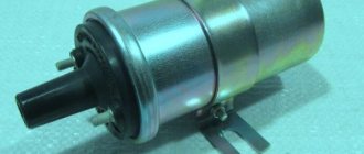
- Ignition coil. A device for converting current from 11 volts to 20 kV for VAZ models has the index 27.3705.
- We select high-voltage wires according to size, and the type is suitable for wiring from a modern Niva.
- Spark plug. A special feature of the spark plugs will be the factory-installed gap between the electrodes of 0.7 to 0.8 mm.
Before installing all elements of contactless ignition, we be sure to prepare a set of necessary tools:
- electric drill with a drill to match the size of the screws;
- two self-tapping screws;
- Phillips screwdriver;
- a set of keys.
The procedure for carrying out installation work
To answer the question of how to install a contactless ignition system with your own hands, you should study the sequence of work using the example of a VAZ sixth series car:
- We use a previously installed breaker-distributor. We remove the cover and dismantle the high-voltage wires.
- We set the “resistor line”. By short turns of the motor we achieve the position of the resistor - perpendicular to the motor body. Further rotation of the crankshaft is not allowed.
- We make a mark for the placement of the distributor. On the engine body we apply a stroke opposite the middle mark of the ignition angle adjustment device.
- We are dismantling the previously installed breaker-distributor. We disconnect it from the ignition coil and at the place of installation on the engine.
- We install the purchased contactless distributor. We remove the top cover and place it in the nest, taking into account the previously installed mark, and secure it. The device must be adjusted in advance.
- We are replacing the ignition coil in place of the previously installed device. We connect the power wires.
- We place all the wires in their places - high-voltage wires to the spark plugs, the wire between the distributor and the coil.
- We install the switch. To do this, we drill holes for fastening in the free area of the engine compartment, and after placement, we include them in the overall scheme.
- Before starting the engine, check again that the connection is correct in accordance with the diagram. It is easy to do it yourself or find it included in the equipment package.
https://youtube.com/watch?v=NbtcE2rEgPQ
Possible causes of failure
During the operation of the internal combustion engine, various malfunctions are possible. To detect them, you should perform the following sequence of actions:
- First you need to start the car. The engine should idle. At this time, you should listen to what sounds are coming from the exhaust pipe. If you hear regular popping noises, then one of the cylinders is faulty. The cause may be faulty spark plugs and lack of spark. The malfunction can also be caused by a large amount of incoming air or insufficient compression in the cylinder.
- It is necessary to inspect the candles. If there is carbon deposits, moisture or oxidation, you need to clean it. Check the gap between the electrodes, which should be 0.8 - 0.9 mm.
- Replace all spark plugs, regardless of their appearance and vehicle mileage.
- If there are irregular emissions, you need to inspect the high-voltage wires. There should be no traces of oxidation on their tips, and the insulation should not be damaged. If defects are found, the wire should be replaced.
Replacing the distributor
Before you begin removing the distributor (ignition distributor) on a VAZ 2109-2108, you must disconnect the negative terminal from the battery
This procedure is not as difficult to perform on your own as it might seem, but there are very important points that are worth paying attention to
This will be discussed in detail during the description of the procedure. To perform this repair you will need the following tools:
- 10 open-end wrench or socket wrench
- Socket head and ratchet handle
- Phillips blade screwdriver
The procedure for removing and installing the distributor on a VAZ 2109-2108
So, before you begin removal, pay attention to the installation position of the distributor relative to the body. Be sure to remember or mark it so that when installing it, put it in the same position
distributor position marks on VAZ 2109-2108
Then you need to disconnect the high-voltage wires from the distributor cap: 4 spark plugs and one central one from the ignition coil: disconnecting high-voltage wires from the distributor on a VAZ 2109-2108
It is also necessary to disconnect the plug with wires, which is clearly shown in the photo below: disconnecting the plug of wires from the distributor on a VAZ 2109-2108
Then we pull off the thin hose from the distributor vacuum corrector: disconnecting the hose from the distributor vacuum corrector on a VAZ 2109-2108
Now you can proceed directly to unscrewing the nuts securing the VAZ 2109-2108 distributor itself. There are three of them in total: one is located in the center at the top: nuts for fastening the distributor on the VAZ 2109-2108
And the other two are located on the sides, and it is more convenient to unscrew them with a regular open-end wrench, since a ratchet with a head simply cannot get there. Do not unscrew the side ones completely yet, as you need to set the TDC marks.
But before removing the ignition distributor, it is necessary to install the piston of the 1st cylinder at TDC. To do this, through the hole in the gearbox housing (after removing the rubber plug), you need to align the marks on the housing and the flywheel. With the gearshift lever in the neutral position, use a 19mm key to turn the crankshaft pulley to the required torque. This is what it should look like: setting timing marks on a VAZ 2109
And only after this we unscrew the two remaining nuts and begin to remove the distributor, removing it from the studs to the side: replacing the distributor with a VAZ 2109-2108
If you decide to replace the distributor, then you need to buy a new one, the price of which for VAZ 2109-2108 cars is about 1000 rubles. Before installation, you must remove the cover by unscrewing the two bolts securing it: remove the distributor cover on the VAZ 2109-2108
And when you put it in place, make sure that the outer contact of the slider during installation is exactly opposite the output of the first cylinder on the cover: installing a distributor on a VAZ 2109-2108
That is, after the distributor has been placed on the housing studs, lean the cover and see if the contact position of the runner coincides with the output of the 1st cylinder: correctly set the position of the distributor runner on the VAZ 2109-2108
And after that, we finally tighten all the nuts securing the distributor and install the cover in its place. And do not forget that it is necessary to maintain the original position of the distributor relative to the body in order to maintain ignition timing.
Rich mixture
The engine began to stall and stopped developing maximum power. When cold it may start and stall. In this case, the air-fuel mixture is to blame, where there is a lot of fuel and little oxygen.
It floods the spark plugs with gasoline and they refuse to work. From this you can judge the quality of the fuel mixture. If there is black soot, it is rich, if it is light, it is poor.
I wrote about this in detail in other articles, go to the channel, everything is written there, the link was above.
What to do
Look for the reason. There are several possible sources of problems:
- Mass air flow sensor
. It fails and the ECU receives incorrect readings for preparing the mixture. I wrote how to check it here. - The second lambda was covered with a “copper basin”
. There is also a separate article about it. - In the case of a carburetor, a high level in the float chamber
.
Table 9-4. Purpose of plugs in the MC 2713-02 controller connector
| Plug no. | Plug purpose |
| 1 | EPHH valve control signal output |
| 2 | Supply voltage supply, +12 V |
| 3 | Output to the SZ signal switch |
| 4 | Output to VK signal switch |
| 5 | NO output for diagnostics |
| 6 | Input from carburetor limit switch |
| 7 | UI output for diagnostics |
| 8 | Input H01 for signal from NO sensor |
| 9 | UI input 1 for signal from the UI sensor |
| 10 | Total (weight) |
| 13 | Diagnostic output |
| 15 | Input for signal from temperature sensor (common) |
| 16 | Input for signal from temperature sensor |
| 18 | UI2 input for signal from the UI sensor |
| 19 | Input H02 for signal from NO sensor |
The “Channel Select” signal, or VC (II, in Fig. 9-16, a), has an angular pulse duration of 180° along the crankshaft. The moment of sparking corresponds in cylinders I and IV to the transition from a low signal level to a high one, and in cylinders II and III - from a high level to a low one.
The “Start of reference” signal, or BUT (III, in Fig. 9-16, a), is generated once per revolution of the crankshaft. The transition from low to high level corresponds to the position of the pistons of cylinders I and IV at TDC.
The “Angular impulse” signal, or UI (IV, in Fig. 9-16, a), is generated 128 times (according to the number of teeth on the flywheel rim) per revolution of the crankshaft. Therefore, the period of the UI signal is 2.8° along the crankshaft.
All controller outputs are designed as an “open collector” transistor of an npn structure with a load capacity of no more than 10 mA.
The purpose of the plugs in the controller connector is given in table. 9-4.
The switch is two-channel, type 42. 3734. Based on the control pulses (SZ and VK) of the controller, it produces:
— alternate switching on of channels and, consequently, ignition coils;
— formation of current pulses during the time tн (Fig. 9-16, b) accumulation in the primary windings of the ignition coils;
— the amplitude of the current pulses I— (see oscillogram V in Fig. 9-16, b) is equal to 8-10 A, and the accumulation time to in the crankshaft speed range from 750 to 4500 min1 and with a supply voltage of 14 V should be 9 -4 ms. The amplitude of the voltage pulses U— (see oscillogram VII) on the output transistors of the switch at the moment of interruption of the primary current (I—) is 350-400 V.
The purpose of the output plugs in the switch connector is given in Table. 9-5.
Signs of a faulty switch: how to check the switch yourself.
Purpose and design features of the switch.
A switch is one of the elements of a car's electrical equipment. Its task is to ensure the normal operation of the contactless ignition system. The assembly is fastened in the engine compartment.
The device is reliable, able to withstand severe vibrations and shock loads
This is very important, because the switch housing contains sensitive electronics
The VAZ switch is based on a standard L 497 microcircuit, which controls an “NPN” type transistor.
A special feature of the circuit is the possibility of programming by the user and setting the required delay coefficient. Starting a cold engine directly depends on the correctness of this indicator.
Thanks to precise tuning, you can speed up the crankshaft rotation speed (while eliminating failures in operation) and guarantee high-quality traction of the power unit.
The main parameters of the switch device include:
Voltage range – from 6 to 16 Volts; operating voltage level – 13.5 Volts; ensuring an uninterrupted spark when the crankshaft rotates in the range from 20 to 7000 rpm; switching current – from 7.5 to 8.5 A.
Signs of a faulty switch.
One of the main symptoms of a faulty switch is loss of spark. The engine starts hard and stalls from time to time, causing interruptions in operation.
But there is no need to rush into replacement - it is important to make sure of the reason, because loss of spark can occur for a number of reasons - failure of the Hall sensor, broken timing belt, faulty ignition coil, poor contact in the distributor cap, problems in the wiring, and so on. If the diagnostics of the remaining nodes did not produce results, then we can move on to our “hero”
But how to check the switch, since the device has a very complex design?
If the diagnosis of the remaining nodes does not produce results, then we can move on to our “hero”. But how to check the switch, since the device has a very complex design?
How to check the switch yourself.
Most car enthusiasts don’t bother with diagnostics and simply install a new unit. This method has its advantages. Firstly, there is no need to waste time checking - just install a new part.
Secondly, you can immediately determine whether this is the reason or not. In fact, there is no need to be afraid of the work, because checking the switch takes a few minutes.
So, to carry out work at home, a test lamp (nominal voltage should be 12 Volts) and a standard set of keys are enough.
With their help, you can verify the presence or absence of pulses, and later make a decision about the serviceability of the device itself.
Algorithm for checking the switch:
To begin work, it is advisable to disconnect the battery so as not to accidentally short-circuit the wiring that you will unscrew.
Using an eight-point wrench, unscrew the nut and remove the wiring from the ignition coil marked “K”. This wire is easy to recognize - it is brownish in color and goes to the terminal labeled one on the switch;
Connect this wire through a control light to terminal “K” on the ignition coil, and then connect the battery;
Turn on the engine starter and observe the lamp's actions. If it blinks, then the switch is working. If the light bulb does not show any signs of life, then the only way out is to replace the device.
If there are doubts about the serviceability of a part, the check should be carried out on a special stand (there is always one at the service station).
In this case, it is possible not only to determine whether the product is working, but also to measure the duration of the pulses.
When the first suspicions appear, you should not immediately change the switch or spend money on a specialist. You are quite capable of doing the job yourself.
Moreover, now you know how to check the switch on the VAZ 2109 and other models of the domestic brand. All that remains is to allocate time and prepare a minimum set of tools. Have a good trip and of course no breakdowns.
The task of the VAZ 2107 ignition system is to generate a spark that ignites the air-fuel mixture in the cylinders. In older “classic” models, this works based on the “breaker-ignition coil” connection. On more modern cars, a contactless ignition system is installed, where the VAZ 2107 ignition switch is responsible for sparking.
Switch malfunctions affect the efficiency and performance of the entire ignition system and the vehicle as a whole. Therefore, it will not be superfluous to learn how to check the VAZ 2107 switch and replace it, if necessary.
The microprocessor ignition system is equipped with:
- one coil, which is common to the nodes;
- dual or individual voltage generation device.
Each option has distinctive features:
- the common coil is mounted in devices with microprocessor ignition equipped with a distributor;
- an individual type of coil is mounted on a spark plug, which eliminates the need to install high-voltage conductors;
- Dual-type coils are mounted in direct ignition units. So, a pair of coils are mounted on a 4-cylinder engine. One is installed on a pair of cylinders 1 and 4, and the second on 2 and 3. A high voltage current is generated in each device. A spark is formed simultaneously in two combustion chambers. In one, the prepared fuel mixture ignites, and in the other, the spark works in vain.
Flooding when there is a spark and the starter is rotating
Experienced motorists are faced with situations when a spark appears, the starter rotates, but the lower part of the spark plugs is filled with gasoline. Do not be deluded by the presence of a fire, since this event can occur irregularly under pressure and can be lost while the engine is running.
The cause of the event appears to be excessive pressure in the cylinders. It will be possible to identify the event and the factors that motivate it by monitoring the car on a stand that simulates a combustion chamber.
We recommend paying attention to the valve timing, because their failure will be the cause of wet electrodes. In fuel-injected internal combustion engines, motorists should check the operation of the bypass valve located on the fuel rail
If its malfunctions are ruled out, you will need to find out the gasoline pressure in the rail, because the manufacturer regulates this parameter. Sharp fluctuations and going beyond the specified interval (larger/smaller sides) can block the start of the internal combustion engine or stimulate flooding of contacts for spark ignition.
Diagnostics will need to be carried out for the sensors of the electronic control system and for the injectors. An example of a failure is when the coolant temperature sensor sends incorrect data. In such a situation, the control unit unreasonably over-enriches the fuel mixture. Much less often, the culprit of incorrect impulses is a failed electronic control unit or a malfunction of its software. In this case, problems will appear not only with the ignition.