Print this article Font size 16
The differences between the ignition systems with injection and carburetor engines on the VAZ 2109 are quite significant.
On carburetor versions, the coil and distributor are responsible for ignition distribution. On injectors, this role is assigned to a special ignition module. It includes a pair of coils and control electronics.
How does the SZ work?
Another important difference between the carburetor and injection ignition systems (SZ) is the absence of the need for settings on the electronic type, setting the ignition timing, or adjusting the gaps. The sensors are responsible for distributing the ignition among the cylinders.
Operating principle
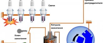
The operating principle of the ignition system installed on the VAZ 2109 is as follows:
- The crankshaft position sensor performs its main tasks, sending a signal to the controllers;
- The controller processes the received information and calculates the sequence of switching on the ignition coils;
- The coil creates two sparks - igniting and idle.
The dry spark method involves creating sparks simultaneously in two spark plugs. One is igniting, and the second is idle, because it beats in time with the release of exhaust gases on the other spark plug. Thus, the cylinders where sparks are generated simultaneously create pairs - cylinders 1 and 4 and cylinders 2 and 3.
Coil
Sparking moment
Spark formation in the ignition system of the VAZ 2109 occurs as follows:
- The rotating ignition distributor shaft simultaneously rotates the screen with slots, which has the shape of a cylinder, and part of its inner surface consists of metal. By rotating, this screen forms an electromagnetic field.
- The highest sensor signal is generated when a metal part of the screen appears in the microswitch gap, and the smallest sensor signal is formed when there is no metal part of the screen in the working gap.
- The moment of signal level changes from higher to lower lasts only from 1 to 5 micro seconds and at this time sparking occurs.
Of course, the sparking process is more complicated and largely depends on the geometry of the screen slits, but there is no point in describing complex physical processes here, since they will not be clear to many people.
Main advantages
The ignition system used for nines has good reliability indicators, although it produces energy up to 50 kJ, and the breakdown voltage can sometimes reach 30 kV or more. BSZ is valued for its high efficiency.
There are several main advantages that characterize contactless ignition systems.
| Advantages | Peculiarities |
| SZ works with a Hall sensor | Because of this, the spark energy parameters are not affected by the voltage in the electrical network or the frequency of the engine. This is due to the fact that the time period of energy concentration in the ignition coil is always constant. This ensures high efficiency of the circuit |
| There is no mechanical interaction between contacts | This ensures there is no contamination or burning of contacts, so there is no need to clean them |
| No need to adjust the position of the contacts | This can be explained simply - they are not in the SZ VAZ 2109 |
| Minimal mechanical interactions between parts | This factor contributes to the absence of rotor vibrations, resonance, and uneven spark distribution across the spark plugs |
| The energy in the candles is constantly increased | It can reach 50 J, which allows you to avoid failures when igniting the air-fuel mixture in the cylinders. This is especially noticeable when accelerating a car. |
| Cost-effective and environmentally friendly | The use of the new SZ made it possible to improve fuel economy by approximately 5 percent, as well as reduce CO emissions by 20 percent |
| Stable cold engine start | Even if the battery is discharged to 6V, you can still start the engine without problems. This makes BSZ significantly different from other ignition systems that cannot boast of such stability. |
Scheme
What's inside the cabin
Replacing the power unit will also require replacing the interior wiring.
Many owners combine this process with replacing the instrument panel with a modern one:
- the “high” panel from the VAZ 21099 fits without modification;
- The “LUX” panel from the VAZ 2114 model is suitable with minor modifications.
The VAZ 2109 wiring diagram for the injector will also be needed to replace the interior wires
Tip: there are a lot of videos on the Internet that describe in detail the process of finalizing the panel. Read them all carefully before starting work on your car.
SZ scheme
The ignition system used on the VAZ 2109 includes the following components:
- Switch;
- Candles;
- Distributor sensor;
- Ignition coils;
- Switch;
- Locking device. It does not allow the starter to turn on until the ignition is completely turned off;
- Locking and anti-theft device;
- Hall Sensor;
- The sensor-distributor roller, which is located horizontally and receives torque from the camshaft;
- System of spontaneous ignition shutdown, which is activated after 2-8 seconds;
- Switched current equalization system, which is required when the network voltage changes within the range of 6-18V;
- The system built into the switch, which regulates the time of energy accumulation in the coil, limits the current strength at low motor operating frequencies.
The ignition system operates with a voltage of up to 26 kV, the spark charge has a duration of 1.6-2.0 milliseconds, and the energy released during this time is 35-50 MJ.
Vacuum regulator
The vacuum regulator, depending on how much the throttle valve is open and the load on the engine has increased, changes the angle of rotation, the maximum value of which for the VAZ 2109 should be in the range from 20 to 24 degrees according to the angle of rotation of the engine crankshaft.
Principle of operation:
- When the engine load increases and the gas pedal is pressed, the throttle valve opens;
- There is a decrease in vacuum in one of the compartments of the vacuum regulator;
- Reducing the vacuum in the chamber leads to movement of the spring-loaded rod;
- The moving rod pulls the plate along with it and rotates the breaker as the rotor rotates, thereby setting a smaller ignition timing angle.
- When the load decreases, the throttle valve closes, the vacuum in the chamber increases and the process occurs in the opposite direction.
Non-contact ignition system device
1. Generator.
Provides electric current when the car engine is running. In particular, it supplies voltage to the ignition system.
2. Rechargeable battery.
Provides electrical current when starting the engine.
3. Fuse and relay mounting block.
Serves for switching wires of low voltage electrical circuits, in particular the ignition system.
4. Ignition coil.
Provides high voltage current to the ignition distributor.
5. Switch.
Provides a pulse for sparking (opening the power circuit of the primary winding of the ignition coil) in one or another cylinder according to a signal from the Hall sensor.
6. Hall sensor.
Generates a control pulse (reducing voltage) for the switch, signaling the need for sparking in one or another engine cylinder.
7. Ignition distributor (distributor) with vacuum and centrifugal ignition timing regulators.
Serves to generate a control pulse to the switch (Hall sensor), distribute high voltage pulses across the spark plugs (“slider”), correct the ignition timing in accordance with the engine operating mode (centrifugal and vacuum regulators).
8. High-voltage wires (armored wires).
They serve to transmit high voltage current from the ignition coil to the distributor cover and then to the spark plugs.
9. Ignition switch.
Serves to close the ignition system circuit. Through it, electric current flows into the ignition system.
10. Ignition relay.
Serves to relieve the contacts of the ignition switch (lock) and supply voltage to the coil and switch.
11. Spark plugs.
They serve to generate a spark in the combustion chambers of the engine and ignite the fuel mixture.
Lada 2109 › Logbook › Dual-circuit ignition on the VAZ 2109
I suffered several times in the winter with starting the engine. Even when it’s not cold, but at 0 degrees, you come to start it and the car is silent. You unscrew the damp spark plugs and the battery eventually dies! With a good battery, it starts normally. As it turned out in the end, I had a contact ignition coil B- 117 from the classics. I immediately changed it to a coil from BSZ. And the car started to start and drive much better, but I didn’t stop there and decided to make a dual-circuit ignition with 2 hall sensors, 2 switches and 2 coils from the Volga ZMZ- 406
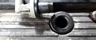
To begin with, I began to assemble the distributor because it is the most basic and subtle part of the system. I took the distributor from OKI as a basis, or an ordinary nine-wheel one. I just had it from the window and was lying in the garage. I completely disassembled it and started installing the 2nd hall sensor directly on the standard platform at an angle of 90 degrees. I marked out the approximate position of the 2nd sensor There are risks at the site regarding the approximate position of the middle of the sensor:
Drilled and tapped the threads for the bolts:
Then I carefully cut the hall sensors themselves with a metal cloth so that they do not interfere with each other. It looks something like this:
Then I modified the shaft, replaced the ignition angle advance weights with nine-shaft ones. They are smaller and lighter than those of the Oka, the photo shows Okushinsky weights! And accordingly, I also replaced the springs. The curtain remained the standard Okushenskaya one, I didn’t touch it. If you make it from a nine-shaft shaft, then you need a curtain too modify it by sawing off two opposite ones so that it looks like in the photo:
That's all for the shaft! Next, I cut out a small piece from the distributor body itself to attach the fork of the 2nd hall sensor, drilled a hole and cut a thread for the bolt
Then I put the whole thing together. Here’s what happened:
Note: during assembly it turned out that the platform on which the hall sensors from the Oka are attached is larger than from the 2109 and it turned out to be easier to mount the sensor, so another one +, It is advisable to buy the same sensors themselves in the same store from the same batch as they are slightly different! That's all for now with the distributor!
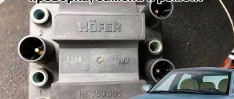
Then I bought the rest of the necessary parts: 2 coils from the Volga ZMZ-406, a wiring harness for the BSZ 2108, an “Astro” switch, as I already had the same one
I connected the wiring according to the diagram:
Note: when connecting according to scheme 1, the tachometer will show half the revolutions. If you want to make a normal tachometer, then there is also scheme 2, there you will need to solder 2 KD213A diodes. But I did not do this and did it according to scheme 1. And don’t try to connect wires without diodes according to scheme 2, as you parallel both coils and it turns out that all 4 spark plugs spark simultaneously when both hall sensors are triggered! Tested personally)
I made a metal mount for the coils, but it didn’t turn out very well:
And now about the most important thing: for the system to work well, you need to adjust the synchronization of the hall sensors so that the spark on all cylinders is the same advance. To do this, you need to make the opposite mark on the flywheel, this will be the TDC of the 2nd cylinder. You need to count 64 teeth along the crown from the standard mark .And using a strobe light, combine both marks from the 1st and 2nd cylinders, moving the 2nd hall sensor up and down or both sensors in the direction of the white arrows. To do this, I drilled holes with a thin drill in the sensors to move them.
Numbering of cylinders on different types of engines
As such, there is no strict international system for the location and numbering of engine cylinders. And that's bad. Therefore, before you begin any type of repair of the engine or ignition system, immerse yourself in the Operating and Repair Instructions for your particular car.
Rear-wheel drive 4- and 6-row engines in the USA have a master cylinder number 1 from the radiator, the remaining cylinders are numbered towards the passenger compartment. But there is also reverse numbering, when the master cylinder is considered to be the one closest to the passenger compartment.
For French engines, cylinder numbering occurs on the gearbox side. And the numbering of the cylinders of V-shaped engines comes from the right side, i.e. on the torque side.
Front-wheel drive cars typically have a transversely mounted engine. Here the cylinders are numbered on one side, and cylinder No. 1 is located on the passenger side.
V-twin multi-cylinder engines have the driver's side master cylinder in the bank closest to the passenger compartment. Then there are the odd-numbered engine cylinders, and on the opposite side (closer to the radiator) there are the even-numbered ones.
Therefore, in order to ensure that you are not completely confused due to the lack of a unified international standard for the location and numbering of engine cylinders, use the manufacturer’s Operating Manual.
Good luck learning the numbering and arrangement of engine cylinders.
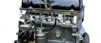
Many motorists, especially beginners who have just purchased a VAZ-2114, have wondered how the 8-valve injection engine that is installed on this car works. This article will discuss the design of the motor, its main characteristics, as well as dismantling and repair features. This information will be very useful for beginners and those who do not know how the main power unit works.
Video about the VAZ-2114 engine
Signs of trouble
There are several types of vehicle electrical wiring conditions in which VAZ 2109 owners are forced to look for breakdowns:
- The vehicle cannot perform its primary function, that is, it cannot drive. Either the wiring diagram of the VAZ 2109 is damaged, or one of the main components of the car is not working.
- The car can drive, but the systems sometimes start to act up or not work correctly.
If, when trying to start the engine, the driver fails, but fuel flows normally into the injector or carburetor, then most likely the problem lies in the wiring:
- If the car runs on a carburetor, then first of all you need to check the spark plugs and high-voltage wire harness. It would not be superfluous to diagnose the distributor, as well as the ignition coil. It also makes sense to check the engine compartment wiring on carburetors.
- When it comes to the injector, often the main cause of the problem is the electronic engine control system. If the system does not allow processing signals from sensors and subsequently cannot issue commands for additional components or mechanisms, then the problem must be looked for in it.
Wiring on the domestic "nine"
In both carburetors and injectors, the cause of electrical equipment malfunction is often burnt contacts, in particular in the ignition switch. If the ignition switch or mounting block cannot work fully, at least the interior lights will not work. In addition, if the devices are faulty, other electrical equipment may also fail to operate, for example, washers, fans, glass cleaners, etc.
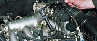
Carburetor internal combustion engine
Before we talk about breakdowns of carburetors and electrical equipment, we suggest you understand the scheme by which the system works:
- When the driver turns on the ignition, but does not start the engine, power is supplied through the high-voltage wiring harness to the motor terminals, and the indicators on the instrument panel light up.
- Next, the starter activates the crankshaft, as well as the entire piston group. In the same way, the voltage through the high-voltage wiring harness starts the generator. The panel continues to work.
- Then power from the device is supplied to the ignition coil, which begins to generate a pulse. The impulse arrives through the high-voltage wire harness to the distributor, the instrument panel works.
- After this, the crankshaft of the motor begins to rotate the distributor drive. The device begins to close the contacts, thus transmitting the discharge through the same high-voltage wire harness to the carburetor spark plugs. The instrument panel continues to operate normally.
Classic ignition
If you cannot start the engine on a carburetor, you need to pay attention to diagnosing the following elements:
- Inspect the electrical wiring between the coil and the generator. You need to check the contacts for breaks or oxidation, sometimes you can simply clean them, in some cases they require replacement. If the electrical circuit itself is in poor condition, then it may make sense to replace the wires.
- You should also diagnose the ignition coil. First of all, you need to check for the presence of a spark. To do this, remove the high-voltage wire from the distributor harness and bring it to the metal elements of the engine compartment. When you try to start the engine by turning the ignition key, a spark should appear from the high-voltage wire. If it is not there, then the coil is faulty and needs to be repaired or replaced.
- In addition, you need to check the distributor chain and the spark plugs themselves. If you see that the high-voltage wires in the harness are in a sad state, then it may make sense to change them. Carry out diagnostics of the internal slider, as well as the carburetor spark plugs themselves (video author - MR. Boroda).
Electronic ignition
The VAZ 2109 can be equipped with an electronic, that is, contactless switch, which is mounted between the coil itself and the distributor. The electronic system is designed to provide a better spark if the engine operates on a lean fuel mixture. If the pulse is too low or completely absent, as you were able to verify when checking for the presence of a spark, then it would be better to change the switch. If the installation of a new device does not solve the problem, it will be necessary to completely or partially change the electrical wiring. There is a possibility that the resistance level in the circuit is very high, and this contributes to a too weak spark.
Problems in the system and their causes
There are several signs that you need to adjust the VAZ ignition on your Nine:
One of the signs that the VAZ 2109 ignition system is not working correctly is a late engine response to turning the key. In other words, the engine takes a long time to start or does not start the first time
Such a malfunction is the first reason to check all components of the system and replace damaged ones. You should also pay attention to fuel consumption. If the amount of fuel consumed has recently increased, it means that the ignition cycle is broken and needs to be adjusted. And the last, most alarming signal is the occurrence of detonation
Due to the early appearance of the spark, the fuel burns unevenly, causing the engine to overheat. During detonation, burnout of the cylinder and piston is often observed.
This occurs for the following reasons:
- In the first case, the spark has insufficient charge to ignite the mixture, which makes it difficult to start the engine. It is necessary to check the spark plugs and other elements of the system.
- Fuel consumption increases due to the fact that the ignition fires later than necessary. It takes a certain period for the mixture to ignite and burn, so the spark must ignite the fuel in time. With late ignition, the mixture burns later and longer than required, which is why the piston mechanism cannot operate at full capacity. As a result of this effect, engine efficiency decreases and fuel consumption increases.
- Another case is when the spark occurs too early and the mixture burns prematurely. There is also a noticeable drop in efficiency, but now it is accompanied by engine overheating. Since the cycle of movement of the piston and the combustion of the mixture do not coincide, the energy of their work will be spent on mutual extinction, resulting in heating of the working parts.
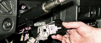
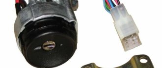
Types of the castle
Let's take a closer look at what ignition switches are. The following types of locks are found on the VAZ-2109 car:
- New sample. The lock has three positions and a short key.
- Old style. The lock has four positions, a long key and an ignition relay, the fourth position is for the parking light.
The key is removed in one position with the system turned off. In the first position the radio is turned on. In the second operating position, all electrical consumers are started. At the starting location, one starter is turned on, and the power supply to the system that consumes power is turned off. When the engine is running, the key returns to the second position. When at rest without a key in the lock, in the zero position, only lighting devices and alarms can continue to operate.
Thus, having studied the ignition switch diagram for the VAZ-2109, it should be noted that the lock consists of mechanics and electrics, where contact wires are located that supply current and thus start the car.
There is a special offer on our website. You can get a free consultation with our corporate lawyer by simply submitting your question in the form below.
Diagnostics using a multimeter
How to check spark plugs with a multimeter? A multimeter is an extremely convenient device for carrying out such diagnostics. It is also called a tester. It should not be confused with a bench test. Stands can be found at service stations. It is completely unsuitable for home use. Checking spark plugs with a multimeter: using probes, you can examine them for the presence of an internal short circuit.
Using a multimeter is quite simple. Moreover, by its design it is not a complex device. How to check the resistance of a spark plug with a multimeter? To identify potential short circuits, the following actions are performed: the probe of this device is placed on the element, the last probe is placed on its base part. If a spark forms upon contact, then there is no problem. It is ready for further use. Here's how to check your spark plugs with a spark plug tester.
Settings
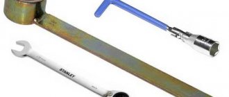
The strobe is used like this:
- the red wire is applied to the “plus” on the coil;
- black – to the body;
- the clamp is connected to the veins installed on cylinder number 4.
After this, the actual adjustment begins.
The work is carried out in the following order:
- start the engine, bring its speed up to 800 and no more (measurements are made with a tachometer);
- the beam from the strobe is aimed at the inspection hatch;
- the long line is placed in the zero position (scale in degrees).
The angle is adjusted by rotating to the right - this increases the angle, respectively, movement in the opposite direction decreases it.
It is not difficult to find out the exact direction - it is indicated by the scale marked on the distributor (there is an o and a “plus” there). Each division corresponds to 8 degrees. For this reason, adjustment is slow. After finding the desired position, the distributor is secured.