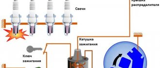
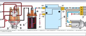
The ignition system of the VAZ 2106 car in the figure is represented by a distributor (3), a reel (6), spark plug elements (5), an ignition switch (2), wires with high voltage insulation, which are distributed to spark plug elements and a coil from the distributor and low-voltage connecting wiring .
In addition to the contact ignition system of the VAZ 2106, the “sixes” also use an ignition circuit using transistors that switch the current pulse and supply it to the spark plugs.
These include:
- Breaker-distributor. Initially, the first models until the 80s of the twentieth century were equipped with the R-125B device. It was equipped with a mechanical octane corrector, which adjusted the angular value of the ignition timing in a small range, but it was not equipped with a vacuum type regulator. After this, the ignition and fuel supply systems were modernized, as a result of which a distributor with a regulator of the vacuum operating principle and a compatible “Ozone” carburetor appeared.
- Bobbin B117-A is a contour type, with a disconnecting magnetic circuit, filled with special oil, sealed.
- Spark plugs A17DV or their export analogues.
- Ignition switch VK347 with an anti-theft gadget, operating on the following principle: after the ignition key is moved to position III “Parking”, a metal lock pops out of the body part, which falls into a special groove in the steering shaft and does not allow it to rotate.
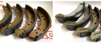
For emergency repairs of the ignition system of a VAZ 2106 car, it is necessary to have in stock the parts that most often fail. This is a reel and a distributor capacitor; they do not take up much space. Unfortunately, they cannot be repaired.
Malfunctions of the “six” ignition system
When operating a vehicle, the following malfunctions of the ignition system occur, which must be eliminated before further driving the vehicle.
| Malfunction | Remedy |
| The contact group has a coating of dirt, is oxidized or there are contact burn points, the distance between the contacts is increased | It is necessary to clean the contact group and adjust the gap |
| Weak fasteners or wiring caps in the low-voltage circuit have oxidized, a broken wire or a short circuit to the car body | Test the wiring and their connections, replace damaged sections of the circuit |
| Defective ignition switch (no contact closure) | Test the area, replace the defective contact element of the ignition switch |
| The capacitor is broken and does not hold capacity | Replace the product |
| There is no voltage in the primary type bobbin winding | Replace the product |
| Incorrect adjustment size in the distributor contact group | Set recommended size in contact group |
| Excessive wear of the PCB pad or increased diameter of the distributor lever bushing | Replace contact group |
| Defect in the bearing of the movable type distributor plate | Replace the bearing or the entire distributor |
| The ignition spark plug elements have an uncertain contact in the threaded part of the cylinder head, the spark plug caps from the insulated HV wires have broken or become oxidized; the insulated HV wires are dirty or their insulating layer is damaged | Test the contacts and, if necessary, restore the joints, clean or change the wiring |
| The corner of the distributor cover has undergone severe wear or has become defective and is in a non-contact state | Check the carbon of the distributor cap and, if necessary, replace it |
| Loss or loss of voltage through chips, through cracks or burnout points in the cover or rotor part of the distributor, as well as through a layer of soot or drops of moisture on the internal cavity of the distributor cover | Carry out a check, clean the cover from foreign layers of moisture and soot, replace the distributor elements (cover and rotor) if they are damaged |
| Failure of the resistance in the slider (distributor rotor) | Replace the slider resistance |
| The car bobbin has external or internal defects | Replace the car bobbin |
| The glow elements of the spark plugs (electrodes) are dirty with oil or the gap between the interacting elements is set incorrectly | Clean the spark plug elements and carry out adjustments to align the gap between the interacting elements |
| Ignition spark plug elements have external defects in the form of cracks and chips on the insulator element | It is necessary to replace spark plug elements with updated products |
| Incorrect connection of high-voltage wires to the contacts on the car distributor cover | Connect the high voltage wires according to the appropriate diagram (1-3-4-2) |
| Incorrect installation of the ignition in the vehicle | Test the installation of the MH and, if necessary, adjust it |
The table below will help you diagnose and troubleshoot problems that may arise.
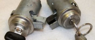
The car is equipped with an engine start lock, typical for the entire line of VAZ cars, consisting of three main parts: a contact part, an anti-theft device and the lock itself.
When the anti-theft device of the lock is released, the device is replaced as a complete set. The contact part, secured in the ignition housing with a snap ring, can be replaced separately. The vehicle starting device is installed under the instrument panel on the driver's left side on the steering shaft bracket.
The flawless operation of any car depends on the trouble-free and coordinated operation of all its mechanisms. Not the last place in this series is the correct installation of the ignition system. After the car leaves the assembly line, the correct clearance is set by factory specialists. During long-term use of the car, a malfunction may occur, which may lead, as one of the reasons, to excessive fuel consumption, or as one of the main reasons, the car will stop starting. In this case, it will be necessary to install the VAZ 2106 ignition according to the factory technical parameters. You can do this yourself, having done all the necessary work yourself, or contact a professional who is familiar with all the nuances of correctly installing the ignition system.
Dismantling the lock cylinder
Before starting this procedure, you need to “read” on the Internet recommendations for replacing the cylinder specifically for your car model, since there are thousands of possible options. It is possible that you will have to drill a hole in the lock structure, for example, as in GOLF 3.
Or AUDI.
In some cases, it is necessary to make “special tools”.
Repair of the lock cylinder
To carry out repairs, it is necessary to disassemble the larva. Its design can be complex, such as in BMW.
If you look closely, you can see that each element of the comb is signed with a two-digit code. We sell repair kits for lock cylinders of different car models. The main choice of repair option is faced by the car owner and the specific situation.
If you have three or four good keys for the car, it is better to purchase a repair kit and “reassemble” the cylinder. Anyone can do this, even without special knowledge. The comb elements are sequentially inserted, starting from the first, and the key is inserted into the cylinder until the metal parts protrude from the cylinder. The element number is recorded. The procedure then continues for the next positions of the larva. The selection is lengthy, but overall the process is creative and entertaining.
There is a simpler and faster repair option. To do this, you need to insert the key into the cylinder along with all the filling and cut off everything that protrudes beyond its limits with an emery wheel. Check for protrusions when installing other keys. Fast, but this option reduces the car’s security against theft.
If your car only comes with one or two keys, it may be cheaper to buy a new key. Then you will have to reinstall the immobilizer chip in the new keys that come with the cylinder. It is necessary to disassemble the new keys and check if they have the necessary cavities to accommodate the chip. If the original keys contain electronics and buttons, this option will not work at all. There may be an option to replace only the metal part of the key.
Electronic ignition VAZ 2106
Ignition system. 1. Insulator; 2. Ignition coil housing; 3. Insulating paper windings; 4. Primary winding; 5. Secondary winding; 6. Primary winding insulating tube; 7. Output terminal for the end of the primary winding; 8. Contact screw; 9. High voltage terminal; 10. Cover; 11. Terminal “+E” for the output of the beginning of the primary and end of the secondary windings; 12. Central terminal spring; 13. Secondary winding frame; 14. External insulation of the primary winding; 15. Fastening bracket; 16. External magnetic circuit; 17. Core; 18. Contact nut; 19. Spark plug insulator; 20. Rod; 21. Spark plug body; 22. O-ring; 23. Heat sink washer; 24. Central electrode; 25. Side electrode of the spark plug; 26. Distributor roller; 27. Roller oil deflector clutch; 28. Washer; 29. Wire for power supply and distributor; 30. Cover locking spring; 31. Vacuum regulator housing; 32. Diaphragm; 33. Vacuum regulator cover; 34. Nut; 35. Vacuum regulator spring; 36. Vacuum regulator rod; 37. Cam lubrication wick; 38. Ignition timing regulator support plate; 39. Distributor rotor; 40. Side electrode with terminal; 41. Distributor cover; 42. Central electrode with terminal; 43. Angle of the central electrode; 44. Central rotor contact; 45. 5-6 kohm resistor to suppress radio interference; 46. External rotor contact; 47. Ignition timing regulator spring; 48. Centrifugal regulator plate; 49. Weight of ignition timing regulator; 50. Insulating sleeve; 51. Breaker cam; 52. Lever insulating block; 53. Breaker lever; 54. Stand with breaker contacts; 55. Breaker contacts; 56. Movable breaker plate; 57. Capacitor 0.20-0.25 µF; 58. Engine start distributor housing; 59. Bearing of the movable plate of the breaker; 60. Oiler body; 61. Terminal clamp screw; 62. Bearing lock plate; 63. Distributor; 64. Candles; 65. Ignition switch; 66. Ignition coil; 67. Generator; 68. Battery; 69. Sensor-distributor; 70. Switch; 71. Ignition timing; 72. To power supplies; 73. I. Ignition coil; 74. II.Spark plug; 75. III. Ignition distributor; 76. IV. Scheme of the classical system; 77. V. Scheme of operation of the centrifugal ignition timing regulator; 78. VI. Diagram of a contactless system.
Ignition installation for VAZ-2106
Before installing the ignition system, it is necessary to check the gap of the breaker contacts, which should be within 0.35 ± 0.05 mm. If the gap does not correspond to these parameters, then it will be necessary to install it using a twelve-sided wrench measuring 39 mm. A control lamp helps to set the ignition correctly on the VAZ 2106.
If there is no test lamp available, then you can install it on a spark by connecting a spare spark plug, which will help prevent system failure during work. The ignition is considered to be correctly set when the spark in cylinder I or IV jumps between the first and second exhaust marks. It is worth adding that in the event of oxidation of the breaker contacts, the control lamp will light constantly, regardless of the position of the distributor body.
The most common cases of malfunction of the VAZ 2106 electronic engine start include: failure of the 900706U ball bearing in the distributors, especially the latest years of production, which are equipped with a vacuum corrector diaphragm, breakdown of the distributor cap, slider and resistor in the slider.
The destruction of the ball bearing leads to uneven operation of the car engine at idle and it stops working at full power, while the tachometer needle can “walk” across its entire scale, regardless of engine speed. This situation can be corrected by performing a few simple steps:
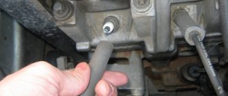
- disconnect the vacuum hose from the distributor;
- Having tied a strong knot at its end, put it away so that it does not dangle;
- use a bar to press the vacuum corrector rod in accordance with Figure 24a; if the bar does not fit between the bend of the rod and the body, then its end is made slightly narrower, as shown in Figure 27b;
- re-adjust the gap in the breaker contacts, as described above;
- set the ignition angle to +7°30'
Now you can drive as with the ignition distributor of the first editions, but it is worth considering that in this case there will be an increase in fuel consumption by approximately a third and an increase in exhaust toxicity.
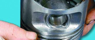
In many ways, the correct operation of the engine starting system depends on the spark plugs installed on it. With just a visual inspection of the spark plugs, you can determine the malfunction of the piston group, ignition and power systems. A spark plug with an oily working surface cannot be restored.
You can try to restore the spark plug by installing it on the second or third cylinders of a well-heated engine, or sandblast the working part. It is recommended to replace spark plugs after every 30,000 km. mileage
02/23/2013Found a mistake? Select the text with the mouse and press Ctrl+Enter Was this information helpful?
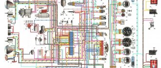
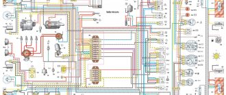
The VAZ-2106 car was produced from 1976 to 2008. This guide provides color-coded wiring diagrams (for the injector and carburetor) with a description of all elements for various modifications. The information is intended for self-repair of the six. Electrical circuits are divided into several blocks for ease of viewing via a computer or phone; there are also circuits in the form of a single picture with a description of each element - for printing on a printer. All electrical equipment of a car can be divided into the following components:
- engine starting system;
- battery charge elements;
- fuel mixture ignition system;
- elements of external and interior lighting;
- sensor system on the instrument panel;
- sound notification elements;
- fuse block.
Examination
Having finished setting the ignition, proceed to check the functionality of this unit:
- get behind the wheel;
- start the engine;
- get out onto a straight section of the road;
- accelerate to 40 kilometers per hour;
- shift the car to fourth gear;
- quickly release the gas.
When everything is done correctly, detonation will occur, causing the fingers to rattle. The noise will disappear as you gain speed.
If the sound does not go away, then the adjustment was made incorrectly and the ignition started early. In this situation, the distributor rotor is turned by half or one division (clockwise). Delayed detonation indicates late ignition timing. Here you will have to turn the distributor in the opposite direction.
After setting the settings, repeat the test described above.
When the ignition is adjusted perfectly, mark the optimal position of the distributor relative to the cylinder block with a line (scratch it or use oil paint). This completes the ignition setting.
VAZ2107 fuse and relay diagram
The electrical wiring of the machine is protected by fuses, which are mainly installed in the central and additional units, located at the bottom of the instrument panel on the left side next to the steering column. The circuit from the battery to the terminals and connections is closed when the car ignition is turned on.
Owners of 2106 should be aware that the old design of fuses has long become obsolete, since each time they operate they overheat, which affects the density of the cells. Lack of tight contact between the fuse and the connectors leads to their burning. Therefore, replacement of the fuse blocks is necessary. To avoid unnecessary problems with the electrical wiring, you should inspect the safety devices every six months. If the contact part burns, it is necessary to replace the fuses and clean the sockets. Today, many VAZ 2106 owners are modernizing classic blocks, replacing them with modern blade fuses.
5avz.jpeg
The VAZ 2106 fuse diagram is one of the simplest. It presents two lines with automotive fuses. This structure is attached with two nuts to the machine body. If you need to remove the fuse line, you will have to disconnect the battery. The disadvantages of such a fuse circuit (block) are its inconvenient covers.
The main disadvantage is that due to the unbending legs, contact sometimes disappears. And in some cases, as a result of poor contact, the fuse heats up and, as a result, the plastic ruler melts. This drawback can easily be corrected by replacing the block with fork-shaped fuses. It will take 10 minutes, but in the future, thanks to this “do-it-yourself VAZ 2106 tuning”, you will get rid of various hassles associated with electricity.
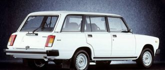
Modifications of the VAZ-2106 car
VAZ-21060 . Modification with the symbol VAZ-21060, Izhevsk assembly of recent years of production with a VAZ-21067 injection engine with a catalyst that meets the Euro-2 environmental standard
VAZ-21061 . Modification with a VAZ-2103 engine, some cars with a similar index were equipped with a simplified engine cooling system and did not have an electric fan. Instead, an impeller was installed on the end of the coolant pump shaft. Already Russian cars were equipped with bumpers from the VAZ-2105, some examples were equipped with cleaners and headlight washers.
VAZ-21062 . Export, right-handed modification of the base six.
VAZ-21063 . A car with an improved VAZ-21011 engine, with an oil pressure sensor and an electric engine cooling fan. The release of this modification was completed in 1994.
VAZ-21064 . Export, right-handed modification, like the VAZ-21062, but the VAZ-21061 modification was taken as the basis
VAZ-21065 . A modification of the car with improved equipment, which was produced from 1990 to 2001. An engine with a volume of 1569 cm3 was installed as a power unit. Other differences from the base model include a more powerful generator, a 5-speed gearbox, a rear axle gearbox with a gear ratio of 3.9, a contactless ignition system, and a Solex carburetor. There were other changes both in the exterior and in the interior, in general it was a “luxury” version of the VAZ-2106 sedan.
VAZ-21065-01. The same VAZ-21065 but with a VAZ-2103 engine
VAZ-21066 . Export, right-hand drive modification of the VAZ-21063 car.
VAZ-21068 . A car that was produced as a carrier of units during the development period of the new VAZ-2108 and VAZ-21083 engines.
VAZ-21069 . Modification of the VAZ-2106 manufactured by order of the special services. It was equipped with a two-section rotary piston engine VAZ-411 with a power of 120 hp, VAZ-413 with a power of 140 hp.
Connection diagram for the electric motor of the interior heater fan
| Position number on the diagram | Explanation of position |
| 1 | Generator |
| 2 | Battery VAZ-2106 |
| 3 | ignition switch |
| 4 | main fuse box |
| 5 | heater fan switch |
| 6 | additional resistor |
| 7 | electric motor of the interior heater fan ME-255 |
Contact ignition system VAZ 2107
The classic contact system used on the VAZ consists of 6 components:
- Ignition switch.
- Breaker-distributor.
- Spark plug.
- Low voltage wires.
- Ignition coil.
- High voltage wires.
The ignition switch combines two parts: a lock with an anti-theft device and a contact part. The switch is secured with two screws to the left of the steering column.
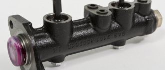
The ignition coil is a step-up transformer that converts low voltage current into the high voltage needed to produce a spark in the spark plugs. The primary and secondary windings of the coil are placed in a housing and filled with transformer oil, which ensures their cooling during operation.
The ignition distributor is the most complex element of the system, consisting of many parts. The function of the distributor is to convert constant low voltage into high pulsed voltage with the distribution of pulses across the spark plugs. The design of the distributor includes a chopper, centrifugal and vacuum ignition timing regulators, a movable plate, a cover, a housing and other parts.
How to properly attach the switch to the heatsink plate
The switch is attached to an aluminum plate. Many people think that this is only necessary to make it convenient to mount and position the switch.
- Of course, it’s more convenient to attach it this way, but there are other reasons.
- The plate acts as a radiator for cooling the switch.
- To fix it, you cannot use the air fastening method.
Be sure to secure the plate on a stable plane with its entire area to the body using two self-tapping screws so that the switch is held and pressed against the body by the entire radiator. Heat from the radiator will transfer to the body, providing more efficient cooling.
Contactless ignition system VAZ 2107
The electronic ignition circuit of the VAZ 2107 received the name “contactless” because the circuit is opened/closed not by the breaker contacts, but by an electronic switch that controls the operation of the output semiconductor transistor. The electronic (non-contact) ignition system kits for the VAZ 2107 on carburetor and injection engines are somewhat different, so there is a misconception that electronic and non-contact ignition are different systems. In reality, the operating principle of electronic ignition systems is the same.
Like a contact ignition system, electronic ignition includes spark plugs, wires, an ignition coil and a distributor. The only difference is the presence of a switch that controls the supply of high voltage to the spark plugs.
BB wires
High-voltage wires, or, as they are also called, spark plug wires, are different from all others installed in the car. The purpose of these wires is to transmit and carry voltage passing through them to the spark plugs and protect other elements of the vehicle from electrical charge.
Spark plug wires provide connection to the ignition coil, distributor and spark plugs
Malfunctions
The appearance of problems with explosive wires is accompanied by the following characteristic signs:
- problematic engine starting due to insufficient voltage on the spark plugs;
- shots at start-up and vibrations during further operation of the engine;
- unstable operation at idle speed;
- periodic engine tripping;
- the appearance of interference during the operation of the radio, which changes when the engine speed changes;
- smell of ozone in the engine compartment.
The main reasons that lead to problems with wires are wear and aging of the insulation. The location of the wires near the engine leads to temperature changes, especially in winter, as a result of which the insulation gradually cracks, moisture, oil, dust, etc. get inside. When cracks reach the conductor, the explosive wire can be pierced to ground, and a spark to the spark plug simply it won't arrive. In addition, wires often fail at the junction of the central conductor and the contact connectors on the spark plugs or ignition coil. To avoid mechanical damage, the wires must be correctly laid and secured with special clamps.
One of the malfunctions of high-voltage wires is a break
How to check
First, you should visually inspect the cables for damage to the insulating layer (cracks, chips, melting)
Attention should also be paid to the contact elements: there should be no traces of oxidation or soot on them. Checking the central core of explosive wires can be done using a conventional digital multimeter
During diagnostics, a broken conductor is identified and the resistance is measured. The procedure consists of the following steps:
- Remove the spark plug wires.
- We set the resistance measurement limit on the multimeter to 3–10 kOhm and connect the wires in series. If the current-carrying wire breaks, there will be no resistance. A working cable should show about 5 kOhm.
I check the wires for damage and spark breakdown as follows: in the dark, I start the engine and open the hood. If a spark strikes ground, it will be clearly visible, especially in wet weather - a spark will jump. After this, the damaged wire can be easily identified. In addition, one day I was faced with a situation where the engine began to misfire. I started checking with the spark plugs, since the wires had been replaced recently, but further diagnostics led to a malfunction in the cable - on one of them there was no contact with the terminal itself connecting the conductor to the spark plug. After contact was restored, the engine started running smoothly.
Video: checking explosive wires
Which ones to put
When choosing and purchasing high-voltage wires, you should pay attention to their markings. There are many manufacturers of the elements in question, but it is better to give preference to the following:
- BERU;
- NGK;
- PARTS-MALL;
- AMD;
- Bremi;
- Tesla Technics.
Today a large selection of spark plug wires is offered, but it is better to give preference to well-known manufacturers