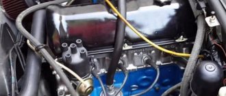
Contact ignition system VAZ 2107
The classic contact system used on the VAZ consists of 6 components:
- Ignition switch.
- Breaker-distributor.
- Spark plug.
- Low voltage wires.
- Ignition coil.
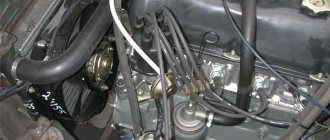
- High voltage wires.
The ignition switch combines two parts: a lock with an anti-theft device and a contact part. The switch is secured with two screws to the left of the steering column.
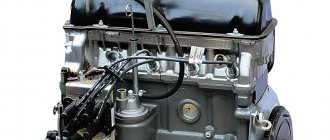
The ignition coil is a step-up transformer that converts low voltage current into the high voltage needed to produce a spark in the spark plugs. The primary and secondary windings of the coil are placed in a housing and filled with transformer oil, which ensures their cooling during operation.
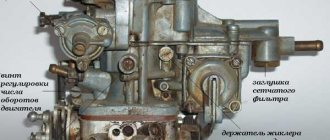
The ignition distributor is the most complex element of the system, consisting of many parts. The function of the distributor is to convert constant low voltage into high pulsed voltage with the distribution of pulses across the spark plugs. The design of the distributor includes a chopper, centrifugal and vacuum ignition timing regulators, a movable plate, a cover, a housing and other parts.
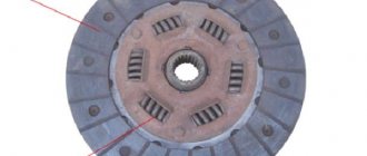
Spark plugs ignite the gasoline-air mixture in the engine cylinders using spark discharges. During operation of the cross sections, it is necessary to monitor the gap between the electrodes and the serviceability of the insulators.
Candles
The spark plug's job is to create a powerful electric spark to ignite the air-fuel mixture. The basis of the candle design is:
- a central electrode through which high voltage current flows;
- ceramic insulator;
- threaded part (skirt);
- side electrode
What spark plugs are used in the BSZ VAZ 2107
In electronic BSZ it is recommended to use spark plugs of the following manufacturers and types:
- A17DV and their modifications (Russia, Engels, ZAZS);
- BP-6 E (Japan, NGK);
- W20-EP (Japan, DENSO);
- L15Y (Czech Republic, BRISK);
- W-7D (BERU Germany, BERU).
The interelectrode gap for spark plugs for BSZ should be in the range of 0.7–0.8 mm
Table: main characteristics of BSZ spark plugs
| Characteristics | Indicators |
| Height of the threaded part, mm | 19 |
| Thread type | M14/1.25 |
| Heat number | 17 |
| Gap size, mm | 0,7–0,8 |
Contactless ignition system VAZ 2107
The electronic ignition circuit of the VAZ 2107 received the name “contactless” because the circuit is opened/closed not by the breaker contacts, but by an electronic switch that controls the operation of the output semiconductor transistor. The electronic (non-contact) ignition system kits for the VAZ 2107 on carburetor and injection engines are somewhat different, so there is a misconception that electronic and non-contact ignition are different systems. In reality, the operating principle of electronic ignition systems is the same.
Ignition adjustment
At home, you can set the ignition timing “by ear”, setting the timing so that in this position the speed of the warmed-up engine is the highest and most even. When driving at a speed of 50 km/h in fourth gear, when the gas pedal is fully pressed, a “knock” sound should occur until the speed increases by 3-5 km/h. If the sound is heard longer, the advance angle must be reduced.
In a car service center, ignition adjustment is carried out using specialized equipment.
Domestic classics are not legendary for their reliability. Sometimes various faults occur in the electrical wiring that interfere with the normal operation of the engine. In this case, for repairs you will need a color wiring diagram with a description that will allow you to understand all the nuances of the wiring. This article presents a diagram for VAZ 2022 or 20174 models with a carburetor, produced from 1988 to 2001, on which a 37.3701 generator was installed.
How to check the distributor
The most common manifestations of an ignition malfunction will be as follows:
- floating idle;
- engine that won't start;
- engine stalling while driving.
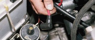
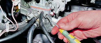
Most often, the cause of this may be the distributor. The easiest way to check the performance of the ignition, including the distributor, is as follows. To do this, unscrew the spark plug, bring it to the engine and start it, observing the appearance of a spark. If it is not there, then you need to check the functionality of the high voltage wires. If there is no spark again, then the diagnosis is clear - the distributor has failed.
In this case, you need to visually check the condition of the slider, the condition of the contacts and the distributor cover. Burnt contacts are cleaned and dust and debris are removed from the internal surfaces of the distributor. In a workshop or garage, you can check the performance of the ignition and distributor using measuring instruments and indicators.
The distributor appeared on the car almost simultaneously with the gasoline engine, and for many years remained almost unchanged, including on domestic cars of the 2109, 2106, 2107, 2108 family. And only after the advent of a modern element base, which includes the Hall sensor, gave way to contactless and then microprocessor ignition systems. » alt=»»>
Explanation of symbols
Knowledge of the definitions of the 2107 Lada electrical circuit will help you quickly locate the required wire, diagnose it, identify and fix the malfunction. Of course, when replacing the cabin filter or changing the oil, such information will not be useful, but in specialized matters, deciphering the symbols will significantly simplify the repair process.
- 1 – head lights VAZ 2017;
- 2 – side turn signals;
- 3 – battery;
- 4 – starter activation relay;
- 5 – carburetor electro-pneumatic valve;
- 6 – internal carburetor switch;
- 7 – generator system 37.3701;
- 8 – gearmotors for headlight cleaners*;
- 9 – fan motor activation sensor;
- 10 – electric motor of the engine cooling fan;
- 11 – sound signals;
- 12 – ignition distributor;
- 13 – spark plugs;
- 14 – starter;
- 15 — coolant temperature indicator sensor;
- 16 – engine compartment lighting;
- 17 – critical oil pressure indicator sensor;
- 18 – warning lamp for insufficient brake fluid level;
- 19 – windshield wiper electric motor;
- 20 – power system valve control unit;
- 21 – ignition coil;
- 22 – electric motor of the headlight washer pump*;
- 23 – electric motor of the windshield washer pump;
- 24 – mounting block;
- 25 – windshield wiper relay;
- 26 – hazard warning and direction indicator relay;
- 27 – brake light switch;
- 28 – reverse lamp switch;
- 29 – ignition relay;
- 30 – ignition switch;
- 31 – three-lever switch;
- 32 – alarm switch;
- 33 – plug socket for a portable lamp**;
- 34 – heater heater fan switch;
- 35 – additional switch for the heater electric motor;
- 36 – indicator lamp for turning on the heated rear window;
- 37 – indicator lamp for insufficient brake fluid level VAZ;
- 38 – signaling unit;
- 39 – electric motor of the stove fan;
- 40 – glove compartment lighting lamp;
- 41 – lamp switches on the front door pillars;
- 42 – switches for warning lights of open front doors***;
- 43 – alarm lights for open front doors***;
- 44 – connecting block;
- 45 – cigarette lighter;
- 46 – hours;
- 47 – instrument lighting switch;
- 48 – diode for checking the serviceability of the warning lamp for insufficient oil pressure and brake fluid level;
- 49 – fuel level indicator;
- 50 – indicator lamp for insufficient gasoline level (fuel reserve);
- 51 – speedometer;
- 52 – control lamp for turning on the direction indicators on the dashboard;
- 53 – warning lamp for the carburetor air damper opening;
- 54 – indicator lamp for battery charge indicator;
- 55 – switch for signaling that the carburetor air damper is slightly open;
- 56 – instrument cluster;
- 57 – econometrician;
- 58 – lamp switches on the rear door pillars;
- 59 – coolant temperature indicator;
- 60 – tachometer;
- 61 – handbrake indicator lamp;
- 62 – low oil pressure indicator sensor;
- 63 – indicator lamp for high beam headlights;
- 64 – signaling device for turning on dimensions;
- 65 – voltmeter;
- 66 – parking brake warning switch;
- 67 – external lighting switch;
- 68 – rear window heating switch;
- 69 – rear fog light switch with on indicator*;
- 70 – fog light circuit fuse;
- 71 – interior lighting lamp****;
- 72 – rear lights;
- 73 – fuel level indicator and fuel reserve sensor;
- 74 – pads for connecting to the rear window heating element*;
- 75 – license plate lights.
Preparation stage
Diagnostics of how the ignition module and each individual coil operates is carried out using a special device called a multimeter or ohmmeter. Its functional task is to show the voltage value supplied by the ignition module. As a result of diagnostics, it is possible to identify the source of current loss in the circuit and, accordingly, the nature of the malfunction. To facilitate painstaking work, it is recommended to dismantle the module outward before starting the process.
Additional designations
When connecting a generator or tampering with the wiring and ignition system of a VAZ, you should know the location of the fuse box in the car. There are 17 of them in total, of which 2 are reserve.
- reverse gear rear lamps;
- electric motors for headlight and glass washer pumps;
- heated rear window;
- direction indicators, hazard warning lights;
- fog lights;
- tachometer, voltmeter, warning lights on the dashboard;
- cigarette lighter and clock;
- sound signal;
- interior lighting, brake lamps;
- high beam headlights;
- high beam warning lamp;
- engine compartment lighting and license plate lighting;
- glove compartment lighting;
- low beam on the right;
- low beam on the left.
The electrical diagram of the VAZ 2022 car will help in repair and maintenance. You can download the image in high resolution using the link.
PROMOTION: SALE OF NEW CAR 2022 PRODUCTION
from 606,900 rub.
from 489,000 rub.
Author of the material: Dumchenkov Mikhail
Did you like the material? Share with your friends:
Have questions about car repairs? Ask them in the consultation section, to do this, click on the link below.
auto mechanic
- Audi
- Brilliance
- Faw
- Ford
- Chevrolet
- Citroen
- Geely
- Haval
- Changan
- Chery
- Datsun
- Great Wall
- Hyundai
- Kia
- Lada
- Volkswagen
- Renault
- Nissan
- Toyota
- Honda
- Mitsubishi
- Opel
- Lifan
- Mazda
- Skoda
- Rest
- Acura
- Alfa Romeo
- Audi
- Bentley
- BMW
- Cadillac
- Chery
- Chevrolet
- Citroen
- Daewoo
- Dodge
- Fiat
- Ford
- GAZ
- Geely
- Hawtai
- Honda
- Hyundai
- Infiniti
- Jaguar
- Jeep
- KIA
- Land Rover
- Lexus
- Lifan
- Lincoln
- Mazda
- Mercedes-Benz
- Mini
- Mitsubishi
- Nissan
- Opel
- Peugeot
- Porsche
- Renault
- Skoda
- SsangYong
- Subaru
- Suzuki
- Toyota
- UAZ
- VAZ
- Volkswagen
- Volvo
- New cars 2019
- New cars 2018
- Test drives
- Jeeps
- Repair and service
- Engine
- Chassis
- Electrical equipment
- Signaling
- Cigarette lighter
- Car Reviews
- Photo and video galleries
- News
- Tires
© 2022 Daciaclubmd.ru. If you do not agree with any provision of this Disclaimer, do not use this Site. Please read Disclaimer and Privacy Policy before use.
Prerequisites for failure
Please note that the engine control system malfunction warning lamp, located on the device panel in the signaling unit, is the first indicator of deviations in the operation of the VAZ 2107, where an injector is used. Some modifications of the VAZ 2107 provide for the location of a warning lamp on the upper insert of the radio panel
By starting the ignition, a system malfunction is tested, which means the lamp lights up and goes out after the engine starts. A prerequisite for diagnosing the ignition system is that the lamp does not go out while the engine is running.
In situations where there is a malfunction, VAZ 2107 owners replace the spark plugs. Old factory spark plugs are usually replaced with iridium spark plugs from NGK or Denzo. Do not forget that only those spark plugs that are designed for the appropriate type of injection are suitable here.
The type of ignition system is no less important in determining the parameters of the spark plug. Often such manipulation does not provide much improvement (plugs have a fairly long service life), so the non-contact ignition system undergoes a full diagnosis.
https://youtube.com/watch?v=mRnm1GVTUmk
Do you want to know more about how to install
valve timing according to marks on VAZ 2101-
VAZ 2107
? And so.
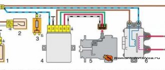
Electrical diagram VAZ-2107 carburetor
Electrical diagram of VAZ 2107, 21074 produced in 1988-2001 with generator 37.3701
- block headlights
- side direction indicators
- accumulator battery
- starter relay
- carburetor electro-pneumatic valve
- carburetor microswitch
- generator 37.3701
- gearmotors for headlight cleaners *
- Fan motor switch sensor
- engine cooling fan motor
- sound signals
- distributor
- spark plug
- starter
- coolant temperature gauge sensor
- engine compartment lamp
- low oil pressure warning sensor
- low brake fluid level indicator sensor
- windshield wiper motor
- carburetor electro-pneumatic valve control unit
- ignition coil
- headlight washer pump motor *
- windshield washer pump motor
- mounting block
- windshield wiper relay
- hazard warning and direction indicator relay
- brake light switch
- reverse light switch
- ignition relay
- ignition switch
- three lever switch
- hazard switch
- socket for portable lamp**
- heater fan switch
- additional resistor for the electric motor of the heater (stove)
- rear window heating indicator lamp
- low brake fluid level warning lamp
- signaling unit
- heater fan electric motor
- glove compartment lamp
- light switches on the front door pillars
- switches for warning lights of open front doors ***
- front door open warning lights ***
- connection block
- cigarette lighter
- watch
- instrument light switch
- diode for checking the serviceability of the low brake fluid level indicator lamp
- fuel level indicator
- fuel reserve indicator lamp
- speedometer
- turn signal indicator lamp
- carburetor choke indicator lamp
- battery charge indicator lamp
- carburetor choke warning switch
- instrument cluster
- econometrician
- light switches on the rear door pillars
- coolant temperature gauge
- tachometer
- parking brake indicator lamp ("handbrake")
- low oil pressure warning lamp
- high beam indicator lamp
- indicator lamp for turning on external lighting
- voltmeter
- parking brake indicator switch ("handbrake")
- outdoor light switch
- rear window heating switch with backlight
- rear fog light switch with on/off indicator *
- fog light circuit fuse
- lampshade ****
- tail lights
- level indicator and fuel reserve sensor
- connectors for connecting to the rear window heating element *
- license plate lights 2107
Wiring diagram VAZ-2107 carburetor - full view:
VAZ 2105 - disassembly and repair of the ignition distributor
September 12, 2013
After the ignition distributor has been removed, you can begin to repair it, the main purpose of which is to disassemble and then replace the failed elements. To repair the distributor on a VAZ 2105 car, prepare a standard set of tools, and then perform the following sequence of actions:
- Wipe the surface of the distributor with a rag to remove dirt.
- Next, we need to knock out the locking sleeve from the oil deflector clutch. To do this, using a mandrel of suitable diameter, knock it out a little, then pick it up with pliers and completely remove it.
- We remove the coupling and the washer located under it from the roller, and then remove the roller itself from the distributor body.
- Now we need to remove the capacitor. To do this, unscrew the screw securing the forked tip of the wire and move it to the side.
- Unscrew the screw securing the condenser clamp to the distributor body and remove it.
- Now we need to remove the vacuum ignition corrector. Use a flathead screwdriver to remove the lock washer from the axle.
- Using a screwdriver, unscrew the two screws securing the regulator to the distributor body.
- Remove the regulator housing.
- Using a flat-head screwdriver, unscrew the two screws securing the contact group, holding the nuts from turning with a 7mm wrench.
- We remove the screws securing the contact group from the housing and remove the tip of the supply wire.
- Unscrew the screws securing the group to the movable plate and remove it from the ignition distributor.
- Now you need to remove the movable plate. First of all, remove the rotor shaft from the housing.
- Unscrew the two screws holding the movable plate. The ground wire tip will be located under one of the screws.
- We remove the movable plate along with the bearing from the housing.
Mounting block connection diagram
P1 — relay for turning on the heated rear window; P2 - relay for turning on the headlight cleaners and washer; P3 - relay for turning on sound signals; P4 - relay for switching on the electric motor of the engine cooling system fan; P5 - headlight high beam relay; P6 - low beam headlight relay; A - the order of conditional numbering of plugs in the mounting block blocks. The outer number with the letter “Ш” in the plug designation is the block number, and the inner number is the conventional number of the plug.
How to set up on the injector
On the injection engine of a VAZ 2107 car, ignition timing adjustments are not required, since the setting function is performed by an electronic control unit that receives the necessary information from sensors.
Checking the correctness of data in the system
- We start the engine and start driving.
- Having accelerated the car to approximately 45 kilometers per hour, we very quickly engage fourth gear and sharply press the gas pedal to the floor.
- We listen to the engine, if detonation, or as car enthusiasts say, “knock of fingers,” is present for 1.5-3 seconds and disappears as acceleration occurs, then the ignition is set correctly, which means no manipulations are required. If detonation does not disappear during acceleration, then the ignition is “early” and you need to turn the distributor clockwise by about 0.5-1 notches. In the case when there was no detonation - the ignition is “later”, you need to turn the distributor 0.5-1 notches counterclockwise.
Schemes of individual blocks of the seven
Power supply system
Power plant starting system
1 - starter; 2 - relay; 3 — ignition switch; 4 - battery
Ignition system
1 - generator; 2 — ignition switch; 3 - distributor; 4 - breaker; 5 — candles; 6 - coil; 7 - battery
Contactless ignition system
External and internal lighting
Windshield wipers and washers
1 — electric motors of the windshield wiper; 2 — washer motor; 3 — mounting block; 4 — ignition switch; 5 - washer switch
Cooling Fan
1 — fan electric motor; 2 - sensor; 3 — mounting block; 4 - ignition relay; 5 - ignition switch.
Replacing the starter relay
Another common problem on VAZ 2107s with a carburetor is a malfunction of the starter relay. When you turn the key in the lock, the system makes a click, but the retractor relay does not operate. Replacing the relay is very simple. First you need to remove the starter from the relay. Unscrew the 2 bolts that secure it. Slide it to the right and take it out, turning it backwards. Unscrew the nuts securing the starter and relay.
Unscrew the terminal. Turn it to the side. Remove the 2 bolts securing the relay to the starter. Remove the relay. Installing a new relay occurs in the reverse order. If you follow these simple steps, your VAZ 2107, which has a carburetor system, will serve you for many more years. In this article we told you about how you can set the ignition on a VAZ 2107 car with a carburetor engine.
Setting the ignition on a VAZ 2107 is easier than it seems. This does not require any special skills or tools. The article describes the complete procedure.
Installing the ignition on a VAZ 2107 is not so difficult. But in this matter you need to be extremely careful and precise, otherwise the whole procedure will have to be repeated.
Wires for connecting electrical appliances
| Connection type | Section, mm 2 | Insulation color |
| Negative terminal of the battery - vehicle ground (body, engine) | 16 | Black |
| Starter positive terminal - battery | 16 | Red |
| Positive contact of the generator - plus battery | 6 | Black |
| Generator - black connector | 6 | Black |
| Terminal on the generator “30” – white MB block | 4 | Pink |
| Starter connector “50” – starter relay | 4 | Red |
| Starter Start Relay - Black Connector | 4 | Brown |
| Ignition switch relay - black connector | 4 | Blue |
| Ignition switch output “50” – blue connector | 4 | Red |
| Ignition switch connector “30” – green connector | 4 | Pink |
| Right headlight plug - ground | 2,5 | Black |
| Left headlight plug - blue connector | 2,5 | Green, gray |
| Generator output “15” – yellow connector | 2,5 | Orange |
| Right headlight connector - ground | 2,5 | Black |
| Left headlight connector - white connector | 2,5 | Green |
| Radiator fan - ground | 2,5 | Black |
| Radiator Fan - Red Connector | 2,5 | Blue |
| Ignition switch output “30/1” – ignition switch relay | 2,5 | Brown |
| Ignition switch contact “15” – single-pin connector | 2,5 | Blue |
| Right headlight - black connector | 2,5 | Grey |
| Ignition switch connector “INT” – black connector | 2,5 | Black |
| Six-pin block of the steering column switch - “ground” | 2,5 | Black |
| Two-pin block of the steering column switch - glove box illumination lamp | 1,5 | Black |
| Glove compartment light - cigarette lighter | 1,5 | Black |
| Cigarette lighter - blue block connector | 1,5 | Blue, red |
| Rear window defroster - white connector | 1,5 | Grey |
What is ignition timing?
For the ignition to work correctly, the following condition must be met: sparking must occur at the moment when the piston is at TDC. This should be a compression stroke. This moment should be the flash point.
| Options | Units | Classical | Contactless |
| Spark energy | mJ | 20 | 60 |
| Secondary voltage rise time from 2 to 15 kV | mks | 30 | 20 |
| Secondary voltage max | kV | 26 | 29,5 |
| Spark duration | ms | 1,5 | 2 |
However, that's not all. The time it takes for the fuel mixture to completely burn must also be taken into account. Therefore, the spark plugs must create an impulse with some advance, which is called the advance angle. As a result, the mixture reaches the peak of combustion, and the cylinder begins to move downward.
If sparking occurs earlier, then such ignition is called earlier, and if late, then later. Early leads to detonation. This is why the engine quickly overheats and becomes inefficient, although fuel consumption can sometimes be greatly reduced. This can be determined by the spark plug electrodes, which are covered with a white coating. With late ignition, power is noticeably lost, and black smoke comes out of the exhaust pipe, which indicates that gasoline, without having time to burn in the cylinder, burns out in the exhaust system.
Car wiring diagram
1 – radiator fan drive motor; 2 – relay and fuse block (mounting block); idle speed sensor; 4 – engine control unit; 5 – potentiometer; 6 – set of spark plugs; 7 – ignition control unit; 8 – electronic crankshaft sensor; 9 – electric fuel pump; 10 – tachometer 2107; 11 – lamp for monitoring the health of electronic systems; 12 – ignition system control relay; 13 – speed sensor; 14 – diagnostic connector; 15 – set of injectors; 16 – adsorber solenoid valve; 17, 18, 19 – fuse block protecting the injection system circuits; 21 – electronic fuel pump control relay; 22 – electronic relay for controlling the intake pipe heating system; 23 – intake pipe heating system; 24 – fuse protecting the heater circuit; 25 – electronic oxygen level sensor; 26 – cooling system temperature control sensor; 27 – electronic air damper sensor; 28 – air temperature sensor; 29 – pressure control sensor.
Electronic ignition device
The electronic ignition circuit of the VAZ 2101, as well as the VAZ 2105, 2106, 2107 or 2109, includes a distributor with a contactless electronic sensor and a steel screen, a switch, a coil with an open magnetic circuit, spark plugs with high-voltage wires and a set of connecting wires.
The advantages of installing electronic ignition on all VAZ classics, no matter whether it is 2106 or 2107, are obvious. Practicality, stable operation, more reliable (powerful) spark generation and high-quality combustion of the mixture, durability, no problems with the contact group, easier engine starting - this is not a complete list
It must also be said about the virtually non-existent ignition breakdowns, improved car dynamics, and a slight but significant reduction in fuel consumption when using a contactless system.
The disadvantages include the rather high price of the VAZ electronic ignition and the possible failure of the Hall sensor. Well, okay, the sensor is easy to replace even on the road. Anyway, let's get started.
Fuse and relay diagram 2107
On newer “sevens” a block with 17 fuses and 6 relays is installed. VAZ 2107 fuses on the “new” unit protect the following electrical circuits and devices:
- Reversing lamps, heater fan, rear window defroster warning lamp and relay, rear wiper motor and rear washer pump.
- Electric motor for front wipers.
- Reserve socket.
- Reserve socket.
- Power supply for heated rear window.
- Clock, cigarette lighter, power socket “carrying”.
- Signal and radiator fan.
- Turn signal lamps in emergency mode.
- “Fog lights” and a relay that regulates the voltage of the on-board network.
- Instrument panel lamps.
- Brake light bulbs.
- Right high beam headlight.
- Left high beam headlight, high beam warning lamp.
- Side lights (rear right, front left), license plate and engine compartment lighting.
- Side lights (rear left, front right), glove compartment and cigarette lighter lamps.
- Low beam (right lamp).
- Low beam (left lamp).
The block relays perform the following functions:
- Heated rear window relay.
- Headlight cleaner and washer relay.
- Signal relay.
- Cooling system electric fan relay.
- High beam relay.
- Low beam relay.
The fuse block of the VAZ 2107 (injector) is no different from the block on the carburetor “seven”. Injection models are simply equipped with an additional relay and fuse box installed in the cabin under the glove compartment. The block includes three relays - the “main” relay, the fuel pump relay and the fan relay.
The key to high-quality circuit testing
Non-contact ignition system checks for short circuits
First, pay attention to the coil winding. To get started, connect a multimeter, which determines the resistance value
There is a recommendation regarding the lubrication of the tip of a high-voltage wire: a special product for the VAZ 2107 or technical petroleum jelly is used here.
The coil itself is diagnosed as follows:
- the module is disconnected from the tips;
- one terminal of the device is connected to the central contact, which has a coil;
- the other terminal of the device is connected to ground.
If the display of the infinity device implies that there is no short circuit, then the coil is in order
Important: unchanged display indicators when ringing the circuit will indicate infinity
Checking the primary ignition circuit involves installing a multimeter to its left and right contacts, which are assigned the ignition function. This setting of the ohmmeter should cause a change in readings. If this is not observed, you can prepare not only to replace the coil, but the entire device. Here they focus on the norm, which is 3-3.5 ohms.
The process of checking the secondary windings of the module includes:
Disconnecting wire tips from it. Level position in front of you. Installing the module to the right outputs of the upper and lower locations
We focus on the indicators that the device displays in seconds. The previous manipulation is carried out similarly with the left outputs of the upper and lower locations. Here we focus on the indicator, the value of which will be no less than 7 Ohms
Recommendation: if at least one coil does not meet the specified indicator, the module as a whole must be replaced, otherwise it will not be possible to avoid a malfunction of the system with a VAZ 2107 where an injector is used
Here we focus on an indicator whose value will be no less than 7 ohms. Recommendation: if at least one coil does not meet the specified indicator, the module as a whole must be replaced, otherwise a malfunction of the system with VAZ will be avoided 2107
where
an injector
, it will not work.
Modifications of the VAZ-2107 car
VAZ-2107 . Basic version of the sedan, with an 8-valve carburetor VAZ-2103 engine, 1.5 liters.
VAZ-2107-20 . The same VAZ-2107, but with a 1.5-liter VAZ-2104 injection engine that meets the Euro-2 environmental standard.
VAZ-2107-71 . The car for the Chinese market was equipped with a VAZ-21034 engine, with a volume of 1.4 liters and a power of 66 horsepower, specially tuned for A-76 gasoline. The pistons were taken from a VAZ-2108.
VAZ-21070 . Modification of a car with an 8-valve, carburetor VAZ-2103 engine, volume 1.5 liters.
VAZ-21072 . Modification with an 8-valve carburetor VAZ-2105 engine, volume 1.3 liters.
VAZ-21073 . An export modification for the European market, which was equipped with a 1.7-liter injection engine with a capacity of 84 horsepower. The engine of this car had a catalytic converter that satisfied environmental protection requirements.
VAZ-21074 . Modification with an 8-valve, carburetor VAZ-2106 engine, volume 1.6 liters.
VAZ-21074-20 . Modification with a 1.6-liter VAZ-21067-10 injection engine, which complies with the Euro-2 environmental standard
VAZ-21074-30 . Like the previous model, but with a VAZ-21067-20 engine, which meets the Euro-3 environmental standard
VAZ-210740 . Modification produced in 2010, equipped with a VAZ-21067 injection engine with a catalyst. Engine capacity is 1.6 liters, power is 72.7 horsepower.
VAZ-21076 . Export modification with a VAZ-2103 carburetor engine.
VAZ-21077 . Export modification with right-hand drive for the UK market. The car was equipped with a VAZ-2105 carburetor engine with a volume of 1.3 liters.
VAZ-21078 . Another export modification for the UK, but with a 1.6-liter VAZ-2106 carburetor engine
VAZ-121079 . The modification, developed specifically for the needs of the Ministry of Internal Affairs and the KGB, was equipped with a powerful VAZ-413 rotary piston engine with a volume of 1.3 liters and a power of 140 horsepower.
VAZ-2107 ZNG . The car is equipped with an 8-valve, fuel-injected VAZ-21213 engine with a volume of 1.7 liters.
“>
Why turn on the ignition?
Incorrect ignition installation is a rather serious problem that haunts owners of cars with ZMZ-402 engines, but we are not talking about it now. The combustion of the flammable mixture must occur strictly at a certain time. If this timing is incorrect, the engine does not perform as it should.
Correct installation of the ignition on a VAZ 2107 can solve several problems, one way or another related to engine operation:
- Motor overheating. Often ignition too early causes detonation. Because of this, the engine temperature changes. The load on the parts of the crank mechanism increases, and its service life is significantly reduced.
Reduced vehicle dynamics. It does not matter before or after switching on, this malfunction will occur in any case. When an explosion occurs when the piston is at top dead center, all the energy from the explosion is transferred to the crankshaft and converted into torque. Therefore, the engine throttle is at its maximum at this moment.
If you set this earlier, the explosion will occur in the direction of the upward moving piston, which also exceeds the pressure in the cylinder. Of course, this slows down the rotation of the crankshaft, despite the considerable inertia of the flywheel.
- If the moment comes later than necessary, the piston will already fail during the explosion. When the piston reaches bottom dead center, the gases will continue to expand and some will escape into the exhaust manifold. Hence the pop in the exhaust manifold.
Installation Guide
How to install BSZ with your own hands on the “seven”? How to properly set and adjust the device? First you need to prepare everything you might need.
Tools and materials
To complete this task you will need:
- a set of keys;
- self-tapping screws;
- screwdriver set;
- construction drill.
Stages
Installation of electronic ignition must be carried out on a de-energized on-board network, otherwise a short circuit may occur in the system.
So disconnect the battery and then follow these steps:
- Disconnect all high-voltage wires from the spark plugs.
- Dismantle the distributor cover.
- After this, by rotating the crankshaft, it is necessary to set the slider to a position perpendicular to the axis of the power unit. Also mark the location on the middle mark of the distribution element scale, this will allow you to make adjustments without any problems in the future.
- The distributor fixing nut must be unscrewed, after which the device is dismantled.
- A non-contact regulator is installed instead of the dismantled distributor, while the slider and housing must be placed in the desired position in accordance with the previously established marks.
- The device cover is installed.
- Then you need to connect the high-voltage cables with the spark plugs.
- After completing these steps, you can replace the coil. In general, this task is quite simple, but when performing it, you should take into account the position of contacts B and K. If they are different on the new short circuit, then the element should be rotated relative to the fastener so that the contacts are located similar to the one that was installed previously.
- At the final stage of installation, the switch is installed; the best option would be to place it between the washer expansion tank and the headlight. The mechanism is fixed using self-tapping screws, and the so-called zero wiring should be brought out under one of them. As for the radiator, it should be leaned against the body.
Damage diagnostics
How to understand that an injector needs to be replaced, checked or repaired? Even without sensors, you can understand that repair of fuel system elements is required if there are 1 of 2 main signs in models 2107, 21074:
- Unstable engine operation. Sometimes it may stall or have difficulty starting.
- A much less obvious sign is loss of power. This effect is noticeable if you mostly drive at medium speeds, but at high speeds it is very noticeable.
- The last sign is recorded only by sensors - the pressure inside the system increases.
The cause of such failures is clogged injectors; even diagnostics are not needed. Cleaning helps restore the engine to its original performance. If the problem has not been resolved after cleaning, it is worth checking the tubes and injectors for damage or breakdowns. In such cases, it is better not to start repairs, but simply replace the damaged parts with new ones.
Sometimes it is impossible to determine on your own where the damage is, and only then will diagnostics at service centers come in handy. A blockage can cause quite serious damage to the VAZ 2107 injector, as well as rupture of channels. The pressure that arises inside the system can easily destroy the most fragile parts. Here you won’t be able to fix the situation with your own hands, even if you have a complete diagram of the car at hand. There is only one conclusion - you need to devote a lot of time and attention to cleaning injectors and do it regularly.