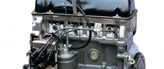
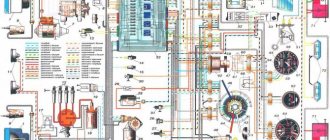
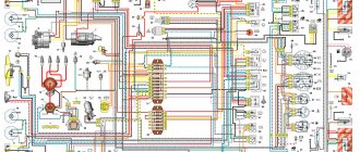
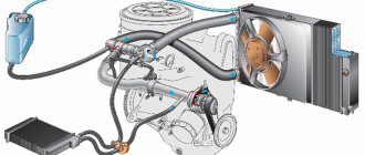
On VAZ 2105, 2107 cars a contact (battery) ignition system is installed. Contact, since the operation of the entire system is based on the opening and closing of the breaker contacts in the distributor. Unlike a similar contact ignition system for cars 2101-2106, the VAZ 2105, 2107 uses switching of low voltage wires through a mounting fuse block.
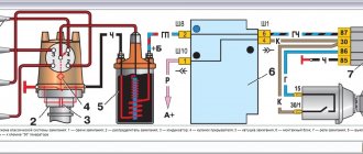
Diagram of the contact ignition system for VAZ 2105, 2107 cars
Elements of contact ignition system
1. Generator
Provides an electric current of a certain voltage to the ignition system when the engine is running.
2. Battery
Supplies the generator with electric current and starts the engine.
3. Fuse and relay mounting block
Switches low voltage wires of the ignition system.
4. Ignition coil
The B117-A ignition coil is non-separable, located in the front left corner of the engine compartment. Generates high voltage current from low voltage current. It has two windings - high and low voltage.
5. Breaker - ignition distributor (distributor)
Distributor breaker R-125V or 30.3706. The breaker mechanically opens the low voltage (12V) current circuit, which signals the ignition coil to generate high voltage current.
Distributor - “slider” alternately distributes high voltage current along high-voltage wires going to the spark plugs in accordance with the operating order of the engine.
6. Ignition switch
It closes the electrical circuit of the ignition system, thereby allowing low voltage current to flow from the generator to the coil.
7. High-voltage wires (armored wires)
They transmit high voltage electric current from the distributor to the spark plugs.
8. Spark plugs
They produce an electric spark at the onset of the compression stroke in a specific engine cylinder.
Notes and additions
— If necessary, the contact ignition system of VAZ 2105, 2107 cars can be converted into a contactless one: “Scheme of the contactless ignition system of VAZ 2105, 2107 cars and their modifications.”
More articles on the ignition system
One of the most common problems encountered on cars is the lack of spark on the fuel spark plugs. If there is no spark from the ignition coil of a VAZ 2107 carburetor, then this indicates problems with ignition. With such a malfunction, the car engine may not start at all or its operation will be unstable when starting. Such a breakdown must be repaired immediately, otherwise it will lead to accelerated wear of engine parts, overheating, increased fuel consumption and other breakdowns. Why the spark disappears on the VAZ 2107, we will consider in detail in the material.
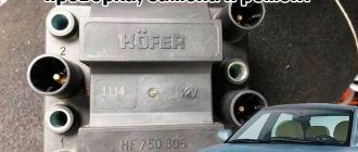
Design and principle of operation of the ignition module
Some old-school motorists call the modules double-spark coils, which makes sense. After all, the coil is the predecessor of the ignition module in the technical evolutionary chain. The module is a paired design consisting of two pairs of windings (primary and secondary) and a switch that alternately switches low-voltage current from one coil to another. In some models of double-spark coils, the commutator is structurally located outside the block .
The operation of the module is controlled from an electronic unit that collects and analyzes information from various working components of the engine. The block, unlike the classic coil, has 4 sockets for connecting high voltage wires going to the spark plugs. The pulse occurs in pairs, first at terminals 1 and 4, then 2 and 3. That is, each of the built-in coils is responsible for the operation of two cylinders. A spark occurs simultaneously, as a pair.
This is what one of the ignition module models looks like. The connector for connecting incoming wires is visible at the top.
At the input, the ignition module has a connector with four terminals. Usually most models have markings opposite them. Pulses from the Hall sensor alternately arrive at contacts A and B, serving as a signal to switch the commutator from one primary winding to another. C and D – ground and power supply (12 V), respectively.
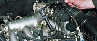
Location of the ignition module VAZ 2107
The ignition module is located on the front side of the cylinder block above the oil filter. It is secured to a specially designed metal bracket using four screws. It can be identified by the high-voltage wires coming out of the housing.
The ignition module is located on the front of the cylinder block above the oil filter
About the drive mechanism
To transmit torque to the distributor shaft on the “six”, a helical gear is used, rotated by a timing chain (in common parlance – “hog”). Since the element is located horizontally and the distributor roller is vertical, there is an intermediary between them - the so-called fungus with oblique teeth and internal slots. This gear simultaneously turns 2 shafts - the oil pump and the distributor.
The distributor drive consists of two transmission gears with oblique teeth
Both transmission links - the “hog” and the “fungus” - are designed for a long service life and are replaced during engine overhauls. The first part is removed after disassembling the timing chain drive, the second is pulled out through the upper hole in the cylinder block.
The VAZ 2106 distributor, equipped with a contact breaker, is a rather complex unit consisting of many small parts. Hence the unreliability of operation and constant failures of the spark generation system. The non-contact version of the distributor creates problems much less frequently, but in terms of performance characteristics it still falls short of modern ignition modules, which have no moving parts.
When should you turn on the ignition?
The first thing you should know is that there are no regulations for this operation, since the ignition timing is set or adjusted only if necessary. It may be caused by the following reasons:
- You recently purchased a “Seven” on the secondary market and are trying to “bring it to mind.”
- After engine repair, accompanied by its disassembly.
- After unscrewing or removing the main ignition distributor (distributor), regardless of the reason why this was done.
- When switching from high-octane fuel to gasoline with a lower octane number and vice versa.
- After replacing the contact group or bearing in the distributor (in cars with an old ignition system).
- mechanical with contacts. switches;
- contactless;
- controlled by an electronic unit (ECU).
Note. On VAZ 2107 vehicles equipped with an electronically controlled injector, the reason for checking the spark generation system may be the flashing of the Check Engine display on the instrument panel. True, it behaves in a similar way when a dozen more malfunctions occur. So ignition problems must first be diagnosed by contacting a service station.
In the vast majority of cases, the sparking moment is set as a result of a violation of the settings after disassembling or repairing the engine. A separate issue is the transition to high-octane gasoline, which requires ignition with greater advance, for which adjustments are being made.
It is advisable to check the timely formation of a discharge on the electrodes of the spark plugs in cases where unstable engine operation is observed, popping noises are heard in the carburetor and exhaust pipe, accompanied by an increase in fuel consumption. If you have not yet discovered the “gluttony” of the car, then pay attention to the color of the smoke; with high gasoline consumption, it is black, as is the carbon deposits on the electrodes of the spark plugs.
Types of systems
For decades, until the release of the VAZ 2107 (from 1982 to 2012), it was equipped with three types of ignition systems:
The note. The first 2 grades were placed on the “seven” of the carburetor, the latter is represented by an injector.
In the mechanical embodiment, the contacts opened by the camshaft cam open the low voltage circuit, initiating the formation of a powerful pulse in the secondary coil winding. This discharge is directed to the fuel spark plug electrodes in the cylinder, where the piston rises to top dead center (TDC) and the compression stroke is completed.
The contactless circuit works on the same principle, only the Hall sensor signals an open circuit, and its switch implements this. Therefore, the ignition settings on the “seven” carburetor are almost identical. One more thing. These are nozzle machines that have a new system that not only has the contacts, but also the distributor and any moving parts. Here, the spark torque is determined by the ECU controller by focusing on the signals from different sensors.
The main components of the distributor and a description of its operation
VAZ classic distributor device
Device
The distributor is assembled in a housing. Inside it, a contact group is mounted on a bearing: moving and fixed contacts or a Hall sensor (for contactless ignition). To correct the advance angle, the vacuum regulator can rotate the contact group at a small angle relative to the housing. The capacitor is attached to the bottom of the case with screws. A drive roller is mounted on bushings in the center of the body. Its bottom has splines with which it engages with the drive gear. In the upper part of the roller there are contact drive cams (for contact ignition) or a steel cup with four slots - a screen (for contactless ignition). At the very top, on a steel platform, two weights and two springs of the centrifugal ignition regulator are installed. A plastic housing with a moving contact and noise suppression resistance of the high voltage distributor (slider) is screwed onto the top with two screws. The entire structure is closed with a lid on two spring latches. The body and cover have a tongue and groove so that they fit together in only one position. The cover contains contact terminals for high voltage wires from the spark plugs and from the ignition coil. The distributor is secured to the engine block using a stud, nut and pressure washer. To adjust the ignition timing, the housing can be rotated relative to the block.
Job
The distributor is connected through the drive to the engine crankshaft and rotates with it. For two full revolutions of the crankshaft, the distributor shaft makes one revolution. This is due to the fact that our engine is four-stroke. When installing the distributor in place, the roller is oriented in strict accordance with the operating order of the engine. This is done so that the contacts open and the spark jumps on the spark plug when the piston of each cylinder, compressing the combustible mixture, does not reach top dead center (TDC) by a few millimeters. This is called ignition advance. When the number of revolutions increases, the distance must be increased, and when it decreases, it must be decreased, which is what the centrifugal regulator does. Its weights, under the influence of centrifugal force, which is greater the higher the engine speed, diverge to the sides and move the cams relative to the roller, making ignition “earlier.” When the engine speed decreases, the springs return the weights to their place and the ignition becomes “later”. This is necessary to increase engine power and efficiency. In addition to the centrifugal one, a vacuum ignition timing regulator is also installed on the distributor. Its function is to fire “earlier” at low throttle opening angles and “later” at sharp throttle opening angles. At idle and at full throttle, the vacuum seal does not work. The regulators are adjusted only at the stands, so there is no need to change the settings yourself.
Preparatory stage
To set the ignition on a VAZ 2107 car, no special conditions are required; the operation can be done both in the garage and on the street, including in winter. For work, prepare the following set of tools:
- flat screwdriver;
- metal probe 0.35 mm thick;
- open-end wrench size 13 mm;
- a car light bulb designed for a voltage of 12 V with wires soldered to it;
- a wrench with a long handle designed to turn the crankshaft;
- key for unscrewing spark plugs.
Ignition tuning tool
Note. Instead of a special key to rotate the crankshaft, you can use a regular open-end wrench measuring 36 mm. If you don’t have such a key, then you will have to set the marks in the old proven way: by engaging 4th gear and raising the rear wheel, turn it manually, thereby turning the crankshaft.
Ideally, it is better to have in your arsenal a device for setting the ignition on a running engine - a strobe light. It is equipped with a lamp that flashes simultaneously with the moment of spark formation in the cylinder, which allows you to see the position of the notch on the crankshaft pulley at idle speed and clearly adjust the advance angle.
This is what a strobe looks like, which is convenient for adjusting ignition timing
Important point. The ignition is set in order to ensure that the spark appears in a timely manner and the engine starts, after which additional adjustments will be required. But the latter will not bring you the desired result when there is no compression in the cylinders or problems with the carburetor make themselves felt. If these faults are not eliminated, the engine operation will remain unstable, no matter how you configure the spark generation system.
Hence the conclusion: you can set the ignition correctly at any time, but to set it well - only on a working engine and carburetor.
Instructions for setting the ignition
If you strictly followed the instructions, connected all the wires according to the diagram and did not misalign the marks, then the motor will start without problems. To adjust the ignition, you need to ensure stable engine operation, so first warm it up for a few minutes, without letting it stall by pressing the gas pedal.
Adjustments can be made on a warm engine using two methods:
- without the use of special devices - “by ear”;
- fine adjustment using a strobe light.
A strobe is a device with a light bulb that flashes simultaneously with the transmission of a pulse by the Hall sensor. When the switched on strobe is brought to the crankshaft flywheel with the engine running, the position of the notch becomes visible. Hence the possibility of precise adjustment.
This is what a strobe looks like for fine-tuning the ignition
To set up, connect the strobe power supply to the battery, and the thick wire to the high-voltage wire of the spark plug of the 1st cylinder. Loosen the distributor fastening nut and bring the flashing lamp to the pulley. Slowly turn the distributor body until the notch on the pulley aligns with the short notch, then tighten the nut.
Tuning in the traditional way “by ear” is done like this:
- Start the engine and loosen the nut holding the ignition distributor.
- Rotate the distributor smoothly and slowly within 15°. Find the position at which the motor operates most stably.
- Tighten the fastening nut.
When adjusting, turn the distributor by the membrane body
It is quite natural that after installing a contactless ignition system, the engine idle speed will increase to 1100-1200 rpm due to the increased spark power. Set the rate to 850-900 rpm by tightening the idle screw on the carburetor and using the tachometer as a guide. On VAZ 2105-2107 carburetors of the “Ozone” type, this screw is located in the lower section of the unit on the right side and is large in size. The VAZ 2108 carburetors of the Solex type (these were also installed on the “seven”) have a long plastic handle protruding from the right (in the direction of travel). The second screw, which regulates the composition of the air-fuel mixture, cannot be turned.
The arrow shows the idle speed adjustment screw.
Tuning on carburetor modifications of the VAZ 2107
All old textbooks on servicing classic Zhiguli models describe a method for setting the moment of spark formation using a light bulb, although experienced motorists can easily do without it. You will understand why this happens as you read this material, but for beginners it will be useful to familiarize yourself with the old proven technique.
To correctly set the ignition of the “seven”, you need to ensure that the following conditions are met simultaneously:
- the notch on the crankshaft pulley is opposite the long mark on the timing cover;
- in this case, the round mark marked on the camshaft chain drive gear coincides with the boss on its body;
- the piston of the 4th cylinder has completed the compression stroke and is at top dead center;
- the contacts inside the distributor are open;
- The movable contact of the slider faces the fixed contact on the distributor cover, where the wire from the spark plug of the 4th cylinder is connected.
Note. On non-contact systems, at this moment the Hall sensor sends a signal to the switch to break the low voltage electrical circuit, which leads to the appearance of a high voltage pulse on the wire leading to the spark plug of the 4th cylinder.
The diagram shows what happens in the cylinders when the marks are aligned
The light bulb is used to control the ignition timing, for which it must be connected with one wire to the “K” contact of the high-voltage coil, and with the second to the vehicle ground. You should know that at the same moment the piston of the first cylinder is also in the TDC position, only there the air-fuel mixture is not compressed, but exhaust gases are released after its combustion. This is why ignorant car enthusiasts often confuse the first cylinder with the fourth when installing the ignition.
Layout of marks on the timing cover
When the above actions occur simultaneously, a spark discharge occurs on the electrodes of the spark plug of the 4th cylinder, as evidenced by the flash of the connected light bulb. To achieve these conditions and set the ignition correctly, follow the instructions:
The marks must be aligned by turning the crankshaft with a wrench
Note. The instructions imply that before starting work the distributor was removed from the engine without aligning the marks.
The ignition is considered to be set correctly if, after installing the distributor cap and connecting the wires, you manage to start the engine, and then you need to adjust the timing. The non-contact system is installed in the same way, with the exception of checking the gap in the contact group due to its absence.
The mark on the camshaft gear is aligned with the boss on the body
Important point. In most cases, the ignition is set without removing the valve cover, which is why the position of the mark on the gear is not visible. You have done everything according to the instructions, but the engine does not start. This means that a spark is supplied to the 4th cylinder during the exhaust stroke, and compression at this moment occurs in the first cylinder. The problem can be solved simply:
- remove the distributor cover;
- unscrew the nut securing it;
- pull the distributor out of the socket, turn the slider exactly 180° and insert the element back;
- Press the distributor skirt with the nut and install the cover.
Advice. If the engine does not start after these steps, but begins to show signs of life, then the problem lies not in the ignition setting, but in a malfunction of one of the system elements.
Photo instructions for setting up
First of all, the marks on the pulley and timing cover are aligned
The distributor is inserted into the hole so that the slider points to cylinder 4. The distributor skirt is pressed to the block with a 13 mm nut.
The gap is checked with a feeler gauge with the contacts open. The gap is corrected if you unscrew the 2 screws securing the contact group. The light comes on when a spark appears.
Troubleshooting
The first sign of loss of vacuum booster seal is not deterioration of the brakes, as many sources on the Internet describe the malfunction. When air just begins to leak through the leaky membrane, the VUT continues to function properly, since the motor manages to maintain a vacuum in the front chamber. The first symptom is changes in the operation of the engine itself:
- due to air leaks into the third cylinder, the engine begins to “trouble” at idle;
- crankshaft revolutions “float”, the stronger the suction, the greater the amplitude of oscillations;
- a running engine reacts to the brake pedal and stalls when pressed sharply;
- Gasoline consumption increases.
Air leaking into the engine through the VUT causes the third cylinder to turn off - the engine begins to “trouble.”
If the car owner ignores the primary symptoms, the situation gets worse - the pedal becomes harder and requires more physical effort to slow down and stop the car. The car can be used further; a breakdown of the VUT does not lead to a complete failure of the brakes, but it significantly complicates driving, especially if you are not used to it. Emergency braking will become a problem.
How to make sure that the vacuum booster is leaking:
- Loosen the clamp and remove the vacuum pipe from the fitting on the manifold.
- Plug the fitting with a tight homemade plug.
- Start the engine. If the revs level out, the problem clearly lies in the amplifier.
- Remove the high voltage wire and remove the spark plug for cylinder III. If the VUT fails, the electrodes will be smoked with black soot.
Whenever possible, I use the old “old-fashioned” method - I simply pinch the vacuum hose with pliers while the engine is running. If the third cylinder starts working and idle speed is restored, I proceed to checking the brake booster.
Similarly, the problem can be temporarily fixed while on the road. Disconnect the pipe, plug the fitting and calmly go to the garage or service station - the power unit will operate smoothly, without excessive fuel consumption. But remember, the brake pedal will become hard and stop responding instantly to light pressure.
Additional diagnostic methods:
- Press the brake 3-4 times and start the engine while holding the pedal. If it does not fail, the valve has probably failed.
- With the engine not running, disconnect the hose from the fitting, remove the check valve and firmly insert a pre-compressed rubber bulb into the hole. On a sealed amplifier it will retain its shape, on a faulty amplifier it will fill with air.
Using a bulb, you can accurately determine the location of the defect, but the vacuum booster will have to be removed. While pumping air into the chamber, wash the edges of the joints and the stem seal - bubbles will indicate the location of damage.
Contactless (electronic) ignition, carburetor
Many car owners are switching to a more accurate (electronic) type of ignition. To adjust the device yourself, you need to have skills in working with the electrical part of a car. If you do not have sufficient knowledge, entrust the work to experienced specialists.
Prepare the instrument for tuning. You will need keys (for “eight”, “ten” and “thirteen”), a Phillips screwdriver, a drill and a pair of self-tapping screws.
Pre-install the contactless system itself, consisting of the following elements:
- Trambler. Start by replacing the distributor by lifting the cover of the latter (this is how you gain access to the “slider”). Place the slider in a position that can be easily adjusted during installation. It is desirable that the notch be on the block opposite the middle mark of the device scale.
Use a “thirteen” wrench to tighten the fastening nut, and then dismantle the assembly. Now disconnect the central wire connecting the coil and the distributor. Mount the non-contact type sensor and adjust the slider taking into account the previously made mark. Align the distributor body along the notches. Replace the cover and return the wires to their place.
- Coil. In the next step, move on to the ignition coil. Take the eight key and twist the wires that are connected to the device. Now use the key to “ten” to push the assembly away from the car body.
Install the new coil taking into account the position of contacts “B” and “K”.
Fix the coil and connect the discarded and new wires to the contact group. Pay attention to the colors of the latter (as a rule, they are identical for the old and new devices). Connect the brown wire to terminal “K” and the blue wire to “B”. Now connect the center wire.
- Switch. Start by choosing a location for this node. In the "seven" the best point for installation is between the headlight on the left side and the washer. In this area there is a flat area on which the device is placed. To begin, lean the switch and mark the mounting locations. After this, screw in the screws. Do not rush to tighten the second fastener - place a black wire under it.
As soon as the described work is completed, check the quality of the connection of the wiring elements and start the engine. The next stage is installing the ignition of the VAZ-2107, which will be discussed below.
Ignition adjustment in static position:
- Find a strobe light. If this is not the case, do the work by ear.
- Loosen the nut holding the ignition coil.
- Start the engine and warm it up.
- Rotate the distributor housing left and right.
- Command your assistant to watch the speed (they should be at 2000 rpm).
- Listen to the engine noise. Try to catch the moments when there are “dips” or changes in rotation speed.
- Achieve a situation where the engine runs smoothly and produces the highest speed. In this case, the work should be as rhythmic as possible.
- Tighten the distributor nut and operate the car.
Setting the ignition timing of the VAZ-2107 in motion:
- Warm up the engine to a temperature of 80-95 degrees Celsius.
- Accelerate to a speed of 40-45 km/h, then move the gearbox selector to the fourth speed position.
- Step on the gas and listen to the engine. If the ignition is set correctly, detonation appears, and after a while the engine speed increases. If you hear a clear knocking of the valves, turn the distributor as the clock hand rotates by about 1-1.5 degrees.
- Perform the manipulations described above until the extraneous sound disappears completely.
- If the speed decreases sharply after pressing the gas, turn the distributor to the same angle, but in the opposite direction.
Remember that adjusting the advance angle may not be enough - often the carburetor itself needs to be adjusted. To do this, find a couple of screws. With one of them you regulate quality, and with the other you regulate quantity. Also clean the carburetor from time to time.
As can be seen from the described technique, setting up electronic ignition on the “seven” is not difficult. At the same time, you can count on serious savings, because at the service station this service will cost a considerable amount.
How to set the ignition on a VAZ 2107 with an injector?
The ignition system of the “Seven” with direct fuel injection operates under the control of an ECU that receives signals from the following sensors:
- crankshaft position;
- air flow;
- throttle position;
- lambda probe.
Multimeter for checking the ignition module
Based on the readings of these sensors, the controller itself determines the moment of spark formation, so the system is not configured in the usual sense. If any problems occur, the driver can only independently check the functionality of the ignition module, to which the high voltage wires from the cylinders are connected. To do this, you need to take a multimeter (ohmmeter) and perform the following steps:
- Disconnect all wires from the module.
- Set the maximum measurement value on the multimeter to 20 kOhm.
- Measure the resistance between the following pairs of terminals: 1 and 4, 2 and 3.
- If the measurement results fall outside the range of 3.6-4 kOhm, then the module is faulty and must be replaced.
The seven with an injector has an ignition module, which you can check yourself
Symptoms of a problem
The reel has a reliable design and its service life is significant. And yet this element can also fail.
The main signs that the ignition coil is not working properly are:
- Inability to start the power plant;
- The inscription “Check Engine” appears on the dashboard (on cars with an ECU), and when scanning the system, code P0363 is displayed, indicating a malfunction of the ignition module (on modern injection cars);
- Decrease in power unit performance;
- Misfires, which causes the engine to “trouble” (with time the problem becomes more pronounced);
- Dips when reaching certain crankshaft speeds.
It should be noted that these malfunctions are also typical for other elements of the ignition system, for example spark plugs, so before you “sin” the coil, you should check the entire circuit coming from it.
The principle of operation of the VAZ 2107 injection engine
The injection system's operating methods are fundamentally different from the operating principles of the carburetor system, in which the air-fuel mixture is prepared in the carburetor chamber. In the VAZ 2107 injection engine, the fuel mixture is injected directly into the cylinders. For this, it received the name “distributed injection system”.
Injection systems are characterized by their operating principle and the presence of different numbers of injectors. The “seven” is equipped with a separate injection system with 4 nozzles. That is, injection occurs in each cylinder, which is controlled by a microcontroller of the electronic engine control unit. Using special-purpose sensors, information about the operating mode, gas pedal position and other important parameters is read. Based on this, there is a controlled flow of fuel into the cylinders.
Photo of ECU VAZ 2107
Not only the quantitative proportionality of fuel and air entering the engine combustion chamber, but also control over the creation of a spark on the spark plugs depends on the electronic control unit (ECU).
Disadvantages of injection models of the VAZ 2107 engine
Of course, as usual, in addition to the advantages of the injection “seven”, there are also negative aspects, which consist in the following situations:
• Problematic access to some components due to the location of the engine and other mechanisms under the hood in the same format as in older models. Although at the same time, the system providing fuel injection is reliable and does not require frequent maintenance during operation.
Photo of VAZ 2107 under the hood
• The injection VAZ 2107 is equipped with a catalyst, which is very easy to damage when driving on a bad road with large bumps and obstacles. In such cases, of course, you need to be careful when driving on problematic roads.
Photo of VAZ 2107 catalyst
• The presence of an injection engine increases the requirements for fuel quality, in contrast to the carburetor version. If you use low-quality gasoline, you cannot avoid clogging the fuel system. This leads to unplanned vehicle maintenance.
• If the injection system breaks down, it is not possible to repair it yourself in a garage. Here you only need to contact professionals at a specialized service station.
What are the advantages of VAZ 2107 injection models?
• The VAZ 2107 injection engine consumes less fuel. At the same time, it is more powerful than a carburetor engine with the same volume. This is achieved through the optimal formation of the qualitative and quantitative composition of the fuel mixture. Accordingly, the efficiency of an injection engine is higher than that of a carburetor.
• Thanks to electronic speed control, the engine runs more reliably at idle, stalls less when starting, and starts well at low ambient temperatures.
• Compared to a carburetor engine, an injection engine does not require frequent adjustments to the ignition and fuel supply systems.
• The air-fuel mixture that enters the cylinders has the most favorable composition. And the existing catalyst controls the minimum amount of harmful exhaust gases. This plays a big role in preserving the environment and taking care of health.
• There is no need to manually adjust the mechanism, since this is done by the hydraulic chain tensioner and hydraulic valve clearance compensators. They also guarantee less noise (noise insulation) when the engine is running.
• Torque graphics are “smooth”, a larger rpm range allows high torque to be achieved.
WORTH NOTICE! On an engine with an injection system, it is possible to install gas-cylinder equipment not only of the 2nd, but also of the 4th generation. This is a more modern and attractive option, since the installation of the 4th generation of gas equipment provides greater savings and reduces the occurrence of “pops” in the engine to zero.
Diagnostics of malfunctions of the ignition module of injection VAZ 2107
The ignition of the injection VAZ 2107 is completely electronic and is considered quite reliable. However, problems can arise with it too. The module plays an important role in this.
Signs of a malfunctioning ignition module
Symptoms of a faulty module include:
- the Check engine warning light on the dashboard lights up;
- floating idle speed;
- engine tripping;
- dips and jerks during acceleration;
- change in sound and color of exhaust;
- increased fuel consumption.
However, these signs can also appear in case of other malfunctions - for example, in case of problems with the fuel system, as well as in case of failure of some sensors (oxygen, mass air flow, detonation, crankshaft position, etc.). If the engine starts to operate incorrectly, the electronic controller puts it into emergency mode, using all available resources. Therefore, when the engine operation changes, fuel consumption increases.
In such cases, you should first of all pay attention to the controller, read information from it and decipher the error code that has occurred. To do this, you will need a special electronic tester, available at almost any service station. If the ignition module fails, error codes in engine operation may be as follows:
- P 3000 - no sparking in the cylinders (for each cylinder the code may look like P 3001, P 3002, P 3003, P 3004);
- P 0351 - break in the winding or windings of the coil responsible for cylinders 1–4;
- P 0352 - a break in the winding or windings of the coil responsible for 2–3 cylinders.
At the same time, the controller can produce similar errors in the event of a malfunction (break, breakdown) of high-voltage wires and spark plugs. Therefore, before diagnosing the module, you should check the high voltage wires and spark plugs.
Main malfunctions of the ignition module
The main malfunctions of the VAZ 2107 ignition module include:
- a break or short to ground in the wiring coming from the controller;
- lack of contact in the connector;
- short circuit of the device windings to ground;
- break in the module windings.
About their device
Before finding out the importance of the elements of the ignition system in question, it is necessary to understand their structure. Structurally, the high-voltage wire consists of the following parts:
- A conductor through which current flows.
- Insulation - rubber or silicone is used as an insulating material.
- Protective caps on both ends.
- Metal contacts.
Each element performs corresponding tasks, and at the slightest violation of integrity, it will be necessary to replace it. Armored wires cannot be repaired, since they play one of the main roles in the car’s ignition system, and also belong to the category of consumables.
To distributor or MZ
It is a mistaken belief that armored wires on a car are ordinary wires that are designed to transmit current from a source to a receiver. As you know, VAZ 2107 cars were produced in two variations of the fuel supply system - carburetor and injector. Although many parts and mechanisms on the carburetor and injector are the same, this does not apply to the GDP. The carburetor VVP differs from the injection one on the VAZ 2107 in the following parameters:
- The length, on which the amount of resistance also depends. The wires on the injection unit are shorter than on the carburetor.
- Fasteners that connect to the distributor on the carburetor and the ignition module on the injector.
- The amount of GDP. There are four of them on the injector, and five on the carburetor.
- Type of caps.
Knowing the design differences, you must also understand that high voltage flows through the wire. The current comes from the distributor or MG through the wires to the spark plugs. The slightest malfunctions lead to the fact that current is not supplied to the spark plug, and a spark does not occur. If a spark does not occur, the cylinder does not work, which negatively affects the operation of the engine.
Possible causes of failure
The weak point of the ignition coils and modules is the secondary winding, which generates a high voltage pulse. A coil break or breakdown may occur in it. The following factors lead to this phenomenon:
- use of low-quality or unsuitable candles;
- operation with non-functioning high voltage wires;
- frequent attempts to check the spark.
The high-voltage pulse arising in the secondary winding must be realized (spent). If this does not happen (if the integrity of a high voltage wire is broken, for example), a high-energy electrical pulse seeks an outlet. He will find it, with a high degree of probability, in the thin secondary winding.
Often, a module malfunction occurs when the integrity of poor-quality factory soldering of wires going to the switch elements is violated. This happens from vibration. Also, the cause of non-working coils can be a banal contact failure in the incoming connector. Another factor leading to a malfunction of the ignition unit is often moisture that gets on the device during washing or driving in unusual conditions.
Checking the ignition module
Checking the ignition module for functionality is carried out in the following ways:
Replacing the ignition module with a known good one
1. The easiest way is to connect a known working module. In this case, the devices must be completely identical, the high-voltage wires are in good condition, and the reliability of the contacts has been checked.
Checking the contacts on the ignition module
2. Moving the module, which allows you to identify unreliable contacts. To do this, move the wire block and the module itself. If during exposure the engine reacts by changing its operation, then the cause of the problem lies in poor contact.
Measuring resistance at the terminals of the ignition module
3. Resistance measurement. To do this, you will need a tester switched to ohmmeter mode. Measurements are carried out on the paired terminals of the module between cylinders 1 and 4, as well as cylinders 2 and 3. The resistance value should be the same and approach 5.4 kOhm.
Checking the ignition module using a tester
4. Check the voltage with a tester. One probe of the device is applied to contact A of the block, the second to ground. After turning on the ignition, take readings from the device. If the wire is in good condition, it will show a voltage of 12 V; if it is missing, check the fuse protecting the ignition module. Then check the continuity of the circuit with a 12 V test lamp. Apply one end of the wire to contact A and rotate the starter. If the lamp does not blink, the circuit is broken. The procedure is repeated in a similar way with other contacts.
Diagnostics of the ignition module with professional equipment
5. Diagnostics at a service station by connecting a computer with special software to the computer. Malfunctions are detected in the form of errors indicated by an alphanumeric code, after which a more in-depth diagnosis of the malfunction is carried out to make a decision - repair the ignition module or replace it. A similar check is carried out at a specialized service station using an oscilloscope.
Product delivery options
Note! Below are the shipping methods available specifically for this product. Payment options may vary depending on the delivery method.
Detailed information can be found on the “Delivery and Payment” page.
Parcel by Russian Post
Available payment methods:
- Cash on delivery (payment upon receipt)
- Using cards Sberbank, VTB, Post Bank, Tinkoff
- Yandex money
- QIWI
- ROBOKASSA
Shipping throughout Russia. Delivery time is from 5 to 12 days.
Parcel by Russian Post 1st class
Available payment methods:
- Cash on delivery (payment upon receipt)
- Using cards Sberbank, VTB, Post Bank, Tinkoff
- Yandex money
- QIWI
- ROBOKASSA
Shipping throughout Russia. Delivery time is from 2 to 5 days. More expensive than regular delivery by Russian Post, approximately 50%. Parcel weight up to 2.5 kg
Express Parcel EMS
Available payment methods:
- Cash on delivery (payment upon receipt)
- Using cards Sberbank, VTB, Post Bank, Tinkoff
- Yandex money
- QIWI
- ROBOKASSA
Shipping throughout Russia. Delivery time is from 3 to 7 days. More expensive than regular delivery by Russian Post, approximately 100%.
Ignition module wiring checks
Procedure:
- Disconnect the block with wires from the ignition module.
- Turn on the ignition.
- Using a multimeter in voltmeter mode, check the voltage between terminal 15 and the ground of the block with wires.
The voltage must be at least 12 V. If it is less or absent, the battery is dead or the ECU circuit is faulty.
Removing the ignition module VAZ 2107
- Remove the air filter housing.
- Disconnect the negative terminal from the battery.
- Remove the high-voltage wires from the ignition module cover.
- Unscrew the three nuts securing the VAZ 2107 ignition module and disconnect it from the bracket.
Before dismantling the ignition module, you don’t have to bother remembering the location of the high-voltage wires. On the body of the device there are numbers indicating the numbers of the cylinders to which each of the terminals of the module should be connected.
Checking the ignition coil
The coil is checked based on two indicators: the presence of a short circuit and an open circuit. Before diagnostics, the ignition coil must be disconnected. After this, one probe of the device is connected to the central contact of the coil, the second to the body (ground). If the display shows resistance equal to infinity, there is no short circuit.
The primary winding of the coil for a break occurs differently. The probes of the device must be connected to the right and left contacts. The resistance between them should be within 3-3.5 Ohms.
If the resistance of the primary winding does not correspond to the norm or there is a short circuit in the coil to the housing, it must be replaced.
Repair
Ignition module VAZ 2107
The design of the ignition module is quite complex: it includes one or more coils, a board, contacts and wires. Of all the above elements, only contact connections can be repaired; in some cases, replacement of parts (transistors, coils) is possible.
The module is dismantled and opened for repair purposes. For this you will need:
- Socket wrenches with heads 1, 13 and 17.
- Hexagon 5.
- Screwdriver.
- Soldering iron.
- Flux for aluminum.
- Stranded wire.
- Nail polish.
Opening the ignition module
Repair of the ignition module is carried out in the following order:
- On the removed device, open the case by prying it off with a screwdriver.
- Remove the silicone film covering the board.
- All aluminum is removed from the explosive contacts.
- On the board, new wires are soldered in place of all the dismantled old ones. To do this, the surface of the collector is cleaned of deposits, after which the board is heated to 180°C (a characteristic smell will indicate when the desired temperature has been reached). During the soldering process, the ends of the wires are connected to the module.
- At the end of the operation, all contacts, the board and the module are covered with nail polish.
- The device is assembled in the reverse order, installed on the car and the engine is started. In case of normal operation, the ignition module is sealed tightly with sealant, while the wires are tucked inside the cavity so that they are not pinched at the edges by the plate.
If the device does not work, then a breakdown inside the module should be looked for more carefully. The transistor, electronic component may have failed, or there may be a break in the coil. Such a repair makes sense only if its price is significantly lower than the cost of a new part.
The process of replacing spark plugs
Required tools and materials:
- Spark plug head 16 mm;
- Spark plug head 21 mm;
- Candle tube;
- Clean rags.
Step-by-step instructions for replacing spark plugs in a Chevrolet Niva:
- Open the hood of the vehicle.
- Remove high voltage wiring. If necessary, take a photo or note the sequence of wire installation.
- Using a feeler gauge, check the gap between the spark plug electrodes.
- Check the gap of the new spark plugs.
- Screw the new parts back in with a torque of 31-39 Nm (the order in which the spark plugs are installed does not matter).
- Install the ignition wires in the same sequence as removal.
The procedure for replacing spark plugs on a Chevrolet Niva has been completed.
Replacing the ignition module of a VAZ 2107
In case of malfunction, it is better to replace the ignition module with a new one. Repair is possible only if the breakdown is not a break or short circuit of the windings, but a visible violation of any connection. Since all the conductors in the module are aluminum, you will need special solder and flux, as well as certain knowledge from the field of electrical engineering. However, no one can guarantee that the device will work flawlessly. Therefore, it is better to buy a new product that costs about a thousand rubles and be sure that the problem with the ignition module has been solved.
Even an inexperienced car enthusiast can replace the module independently. The only tools you will need is a 5mm hex wrench. The work is performed in the following order:
- Open the hood and disconnect the negative terminal from the battery.
- Remove the air filter housing, find the ignition module and disconnect the high voltage wires and the wiring harness block from it.
- Use a 5mm hex to unscrew the four screws securing the module to its bracket and remove the faulty module.
- We install the new module and secure it with screws. We connect the high-voltage wires and the wire block.
- We connect the terminal to the battery and start the engine. We look at the instrument panel and listen to the sound of the engine. If the Check engine light goes out and the engine runs stably, everything is done correctly.
Sources
- https://motorltd.ru/sposobyi-samostoyatelnoy-proverki-modulya-zazhiganiya/
- https://bumper.guru/klassicheskie-modeli-vaz/elektrooborudovanie/zazhiganie/zazhiganie-2107/modul-zazhiganiya-vaz-2107-inzhektor.html
- https://hitmind.ru/275-kak-vystavit-zazhiganie-na-vaz-2107-instruktsiya-po-ustanovke-na-karbyuratore-i-inzhektore.html
- https://sis26.ru/ustanovka-zazhiganija-vaz-2107-inzhektor/
- https://mashinapro.ru/1470-zajiganie-vaz2107.html
- https://vazweb.ru/desyatka/elektrooborudovanie/instruktsiya-po-nastroyke-sistemyi-zazhiganiya-vaz-2107-svoimi-rukami.html
- https://VazNeTaz.ru/publ/stati_o_vaz_2101_2115/inzhektornyj-dvigatel-vaz-2107.html
- https://voditelauto.ru/kak-proverit-modul-zagiganiya/
- https://ladafakt.ru/kak-proverit-modul-zazhiganiya-vaz-2107-inzhektor.html
- https://kalina-2.ru/remont-vaz/porjadok-zazhiganija-vaz-2107-inzhektor
VESKO-TRANS.RU
AutoNews / Reviews / Tests
How to Check the Ignition Coil of a VAZ 2107 Injector
How to check the ignition module of a VAZ 2107 injector
Section 11: Description of the engine control system Car VAZ 2107
Ignition coil of the VAZ 2107 car. Check. replacement
To check the ignition coil of a VAZ 2107, a multimeter is required.
Sequence of work for checking the ignition coil on a VAZ 2107 car
1. Prepare your VAZ 2107 for work (see “Preparing your VAZ 2107 for maintenance and repair”). 2. When removing the clamp, disconnect the wiring block from the ignition coil.
3. Connect the negative voltage measuring sensor of the VAZ 2107 automobile engine and, turning on the ignition, measure the supply voltage at terminal “15” (in the middle) of the ignition wiring harness,
The voltage at the end of the ignition coil gasket should be at least 12 V. If the voltage does not reach the terminal block, or it is below 12 V, there is a fault in the power circuit, a low battery level, or a computer fault. 4. Turn off the ignition on the VAZ 2107. 5. Remove the air filter housing (see “Air filter housing. Removal. Installation”). 6. Clean the ignition coil of dirt. 7. Disconnect the high voltage wires from the ignition coil. 8. Alternatively, connect an ohmmeter to the ignition coil high voltage terminals 1-4 and 2-3 and measure the resistance of the secondary windings. With the ignition coil it should be within 5.0. 6.0 ohms. 9. To check the primary winding for ground, connect the ohmmeter sensors to the middle terminal “15” of the connector and to the metal part of the ignition coil housing. If the resistance tends to infinity, the circuit does not occur. 10. To check for an open circuit in the primary winding, connect ohmmeter probes to terminals “1a” and “1b” of the ignition coil connector. If the resistance tends to infinity, then in the circuit
A breakdown occurred and the ignition coil on the VAZ 2107 had to be replaced. 11. To remove the ignition coil using a 5mm wrench, loosen the four mounting screws and remove the ignition coil. Installing an ignition coil on a VAZ 2107 car
Installing the ignition coil on a VAZ 2107 car is carried out in the reverse order. In this case, the high voltage wires are connected to the ignition coil in accordance with the cylinder numbers printed on the ignition coil housing next to the terminals.
Replacing the coil and ignition module on a VAZ 2101-VAZ 2107
Welcome! Ignition module and ignition coil. they are not the same thing; carburetors use a coil, but the nozzles have an ignition module, inside of which there are two coils (of which they are composed), thanks to these devices the car runs smoothly and moves, for a strong but very short ignition time it takes about 25,000-35,000 Volts, battery can't supply that much power and the alternator doesn't have enough power and then the ignition module comes in and converts the voltage from the battery and the alternator into a higher current through that machine and leaves.
The note! To replace the coil or ignition module, stock up on: a wrench (included), hex wrenches and multimeters are still required to test both units!
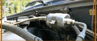
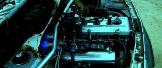
Where is the ignition coil and ignition module? On cars with a carburetor, the coil is secured with two nuts on the left side of the car, next to it is the fuel pump, which is indicated by a blue arrow in photo 1, and the coil itself is shown in one photo, but only along the red arrow, and that for injection cars with an ignition module, it is already attached by four hex bolts to a bracket which in turn is attached to the cylinder block and which will make it easier for you to locate the module onto and then underneath the injector. Oil filter (marked with a blue arrow in photo 2), so check the module for yourself.