The location of the relays and fuses, as well as the differences in the mounting blocks, is here www.drive2.ru/b/538898/
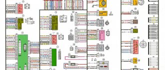
Scheme of VAZ-2108, 2109 with a low instrument panel (early versions)
content-5.foto.my.mail.ru…hofer2107/1348/s-3867.jpg There is a “parking light” function - turning on the left or right lights in the parking lot.
Scheme of VAZ-2108, 2109, 21099 with a low panel (later versions)
content-21.foto.my.mail.r…hofer2107/1348/s-3815.jpg There is no brake pad wear sensor (previously, the handbrake lamp blinked when the lever was raised, and came on constantly when the sensors on the brake pads were activated).
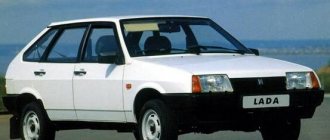
Years of production 2108: 1984—2003 in Russia, 2003—2014 in Ukraine
Scheme of VAZ-2108, 2109, 21099 with a high panel and Euro fuse block 2114
content-21.foto.my.mail.r…hofer2107/1348/s-3812.jpg Fog lights, central locking, heated seats and electric windows.
Years of production 2109: 1987-2004 - in Russia, 2004-2011 - in Ukraine
Connection diagram for headlight cleaners on low and high panels of cars produced after 1989
content.foto.my.mail.ru/m…hofer2107/1348/h-3928.jpg The headlight cleaners are turned on with a button, in place of the relay there is a jumper.
Years of production 21099: 1990-2004 - in Russia, 2004-2011 - in Ukraine
Diagram of a mixture control system with a controller under the hood
content-10.foto.my.mail.r…hofer2107/1348/s-3906.jpg
Diagram for switching on fog lights since 2000 on a high panel
Since 2000, in accordance with UNECE rule 48-01, the electrical circuit for switching on the rear fog lights has been changed on parts of VAZ vehicles. Added rear fog light relay 2114-3747610, and rear fog light switch 21093-3710030-10 (like a regular one, only without fixing). Instrument panel harness used 21099-3724030
We are reworking the activation of the rear fog lights according to the latest scheme. That is, the button will not be fixed: if the headlights or front fog lights are on, press and release the button for the rear fog lights - they turn on. They turn off when you press the button again or automatically when you turn off the headlights. That is, we will never forget to turn them off. For high panel. You need rear fog lamp relay 2114-3747610. It may look different, it is also used on the VAZ-2114, 2110, GAZ-3110... It is advisable to find a connector for it, you can just wrap the usual terminals with electrical tape and stick it in.
Comments 10
I can’t find this, where the green one comes in and where it goes
The green one goes to the size button, light switch, can go to the fuse for the rear fog light button (it is located right next to the button) or can connect to the 3/8 mounting block. In this case, power went to the headlight cleaner fuse and from it to sh3/21 from which power went to the button. That is, in the second option, the fuse in the mounting block is responsible for the headlight wipers (if any) and for the rear fog lights and there is no fuse next to the button. In the second option, there is not a green wire going to the button, but an orange-white one. In the photo ad-cd.net/169d0das-480.jpg the top two pictures are options for connecting the button. So there may not be any green. We check the power on the green or orange-white wire of the button when the ignition and headlights are turned on.
I have an old-style mounting block, can it affect anything?
If you put the wiring under a new type of mounting block, it will not work. Does the button have a green or orange/white wire?
Hi, I had a 21099 96 with a low panel before they changed it to a high one, I can’t do the rear PTF, there are no these wires, what should I do?
I advise you to start by looking for the connector for the button next to the stove control levers where it was on the low panel, maybe it is still there. Then you need to extend it and connect the indicator light next to it (to the black and orange-black).
If there is no connector, then here is a diagram for connecting the rear PTF ad-cd.net/6584a32s-960.jpg Take the button. Contacts 7 to black and 6 to white to the same wires of the glass heating button (backlight), contact 10 through a 10 Amp fuse to the green side button, and contact 9 to the indication light (its second contact is to the black contact 7 of the button, this is a minus) and to orange -black wire for wiring to the rear lights. The wiring runs to the left of the clutch pedal from the mounting block to the floor. You need to find the orange-black wire there, cut it and connect it to the button, or you can press the lock of its terminal and pull it out of plug 9 of the mounting block.
Thank you for such a complete and clear answer)) we will try
I advise you to start by looking for the connector for the button next to the stove control levers where it was on the low panel, maybe it is still there. Then you need to extend it and connect the indicator light next to it (to the black and orange-black).
If there is no connector, then here is a diagram for connecting the rear PTF ad-cd.net/6584a32s-960.jpg Take the button. Contacts 7 to black and 6 to white to the same wires of the glass heating button (backlight), contact 10 through a 10 Amp fuse to the green side button, and contact 9 to the indication light (its second contact is to the black contact 7 of the button, this is a minus) and to orange -black wire for wiring to the rear lights. The wiring runs to the left of the clutch pedal from the mounting block to the floor. You need to find the orange-black wire there, cut it and connect it to the button, or you can press the lock of its terminal and pull it out of plug 9 of the mounting block.
What kind of problems does an electrical circuit help to solve?
The electrical circuit for the VAZ-2109 injector is, of course, several times more complicated than for carburetor cars. However, this is not at all surprising, because models with distributed fuel injection have numerous electronic devices built into them, which, unfortunately, can fail. An interactive diagram helps solve many problems:
- provides the driver with information about the functionality of all electronic devices;
- transmits a control pulse to electronic elements;
- acts as electrical protection for all electronic devices;
- protects the system from short circuits.
Practical advice
The operation of an injection power unit, and in particular the maintenance of its electronic components, is fundamentally different from carburetor engine systems.
Owners of converted cars must learn a few basic rules:
- Before dismantling the injection control system components, be sure to disconnect the negative cable from the battery terminal;
Working with car wiring requires care and precision.
- Do not start the engine if the terminals of the wires on the battery have poor contact. Be sure to check how tightly they are tightened;
- Do not disconnect the battery while the vehicle engine is running. This is guaranteed to lead to failure of the ECU;
- Monitor the ECU temperature. It is not allowed to overheat (65°C when the car is running and above 80°C, for example when drying in a paint booth). If such a process is unavoidable, remove the ECU from the vehicle for the duration of the work;
- It is also necessary to remove the ECU or disconnect it from the vehicle’s on-board system when carrying out welding work on body parts.
Types of electrical circuits
There are several options for circuits for monitoring the condition of electrical equipment of the VAZ-2109:
- With a "high panel". This scheme is considered as the most interactive and relevant. It provides an additional circuit that is intended for an automotive mounting block.
- With a "low panel". This circuit is used to identify a malfunction in the automotive mounting block.
- With Europanel. This version of the diagrams provides complete information for both the internal diagram and the mounting block. It also includes a diagram that helps to connect a Europanel, that is, electrical devices and appliances created according to the “Euro” type.
What can be changed in the electrical circuit
Let's figure out what exactly car owners undergo alterations.
Moreover, we will indicate only those alterations that are not prohibited by the manufacturer and current regulations:
- Installation of a new instrument panel;
- Alteration of internal (interior) lighting;
- Installation of additional turn signal indicators in the rear view mirrors;
- Installation of additional headlights (fog lights);
- Installation of an acoustic and multimedia system;
- Immobilizer installation.
Wiring diagram for VAZ 2109i with a high panel
For reference: the visual differences between the standard panel and the “high” one are that the radio compartment is moved to the level of the dashboard. Accordingly, the wiring on the VAZ 2109 under the instrument panel must be replaced.
Interior modifications
Many owners come to mind with the desire to improve the lighting in the car interior.
Let us remind you that inside a passenger vehicle there are several places equipped with lighting sources:
- The salon itself (interior lighting);
- Glovebox;
- Cigarette lighter;
- Instrument panel (instrument cluster lamp and symbol lamp)
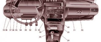
Layout of incandescent lamps for a VAZ 2109 car
If you, as the owner, like a high panel in the cabin, then you cannot do without replacing the standard wiring. Because the:
- Control devices have a different location on the panel;
- The standard length of wires is not enough;
- Terminal blocks may also differ.
Electrical wiring for a VAZ 2109 in the process of connecting to devices
Accordingly, without replacing the electrical wires it will not be possible to use:
- instrumentation;
- on/off buttons for various devices.
Differences in the terminal blocks of the “low” and “high” instrument panel
As for making changes to the instrument panel lighting, today there are sets of special lamps on sale along with the wiring with which they are connected to the car’s electrical network.
Tuned instrument panel lighting for VAZ 2109
You can install such kits yourself; it is only important to adhere to accuracy and safety rules.
Advice: carry out all electrical wiring replacements and connecting instrumentation only with the battery disconnected.
How the signal is transmitted
From the electronic unit, a signal is transmitted through special wires, which are painted in different colors, to the system that controls the functionality of the engine.
Thanks to the different color markings of the wires, the driver can understand the electrical circuit and find exactly the wire that is needed to solve a particular problem. To ensure high-quality and uninterrupted transmission of the electrical signal, you must do the following:
- use wires with a suitable cross-section;
- monitor the contact resistance, which should be minimal for removable connections;
- monitor the integrity of the insulation of electrical conductors.
The operation of the VAZ-2109 injector engine, as well as its dynamic characteristics, is primarily affected by the condition of the electrical wiring, therefore, it must be constantly and carefully monitored.
Having familiarized yourself with the intelligent color wiring diagram, even without the presence of a special measuring device, you can quite easily independently find a fault in the electrical wiring, even the most insignificant one. Eg:
- find out why the ignition stopped working;
- determine why the starter does not turn on;
- due to which the generator lacks voltage;
- which led to a breakdown of the heating system.
If the cross-section of the conductor decreases, this will lead to a deterioration in the transmitted electrical signal, which will subsequently increase the temperature. Sometimes an external examination will not help to identify a violation of the integrity of the veins, and only a deep examination will help to identify such destruction. The integrity of the wiring is compromised due to oxidation of the contacts, and since such a process is inevitable when operating machines, this means that they need to be cleaned periodically.
If the electrical signal is supplied in a distorted form, then the malfunction will be felt throughout the entire VAZ-2109 injector system.
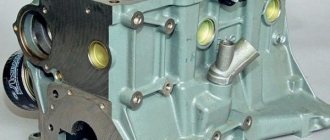
Engine compartment modifications
In addition to replacing the power unit after it has exhausted its life, there are many components in the engine compartment whose wiring also needs to be replaced:
- high-voltage wires from the ignition unit;
- wiring of various control sensors;
- battery power cables (connections are most susceptible to corrosion).
If there is no spark, repair of the electrical wiring of the VAZ 2109 is inevitable.
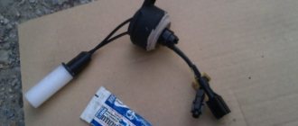
Numerous sensors in the engine compartment require special monitoring:
- Coolant temperature sensor - if the electrical wiring is faulty, the driver will not notice overheating of the power unit;
- Brake fluid level sensor in the expansion tank - a leak or low level can lead to brake system failure;
- ABC system sensors - oxidation of contacts or disruption of wiring integrity can lead to system failure;
- Exhaust gas sensor - based on its readings, the electronic unit “prepares” the fuel-air mixture. If the sensor does not work, gasoline consumption will increase.
The only wireless car security alarm element
A useful addition to the functionality of the car is the acquisition of a modern anti-theft system.
Installing a modern alarm system is a special topic, since its work affects several main components and systems of a VAZ family car:
- General electrical system;
- Supply system;
- Sound and light circuit and actuators (side lights, headlights, sound signals);
- Standard immobilizer.
To install an alarm system, a VAZ 2109 wiring diagram is required
Advice: often manufacturers of alarm systems accompany the installation process with video and photo materials for each specific model of a particular family of cars. Before starting installation, you should read them carefully.
General alterations
Installing additional fog lights is a general modification because:
- Affects equipment in the engine compartment;
- Interferes with the instrument panel inside the cabin;
- Connects to the vehicle's standard power supply system;
- Attached to the power body.
The kit must contain connection instructions
To install and connect fog lights, you will need a wiring diagram for the VAZ 2109, because the package includes:
- Connecting wires;
- Terminal blocks;
- Switching relay;
- Actuators (buttons);
- A backlight lamp (or LED) indicating the status of lighting fixtures.
Additional tips from the professionals
By taking into account some tips and tricks provided by professionals, you can independently extend the life of your car wiring:
- car owners must periodically inspect the external condition of the insulation and all connectors by looking under the hood of their car;
- If a minor defect is discovered during inspection, the damaged wire must be replaced to prevent a short circuit. If the break is insignificant, then you can wrap it with high-quality electrical tape for a while, but it is not recommended to postpone replacement for a long time;
- A special product, WD-40, which can be purchased at an affordable price in a specialized store, will help remove the oxidizing layer from the surface of the connector;
- It is advisable to make additional protection for the engine crankcase to prevent moisture from getting on the wires.
It is imperative to wipe off excess oil from the insulation to extend its service life. Experts strongly recommend replacing old or damaged wiring rather than repairing it, in order to avoid more serious breakdowns in the future, which will cost car owners several times more.
Schematic electrical diagrams, connecting devices and pinouts of connectors
The VAZ-2109 car was produced at AvtoVAZ from 1987 to 1997. Years of production 21099: 1990-2004 - in Russia, 2004-2011 - in Ukraine. Here are colored wiring diagrams (for the injector and carburetor) with a description of all the elements for various modifications. The information is intended for self-repair of cars. Electrical circuits are divided into several blocks for ease of viewing via a computer or smartphone; there are also circuits in the form of a single picture with a description of the elements - for printing on a printer.
Modifications of VAZ-2109
VAZ-2109 . The basic model, which was produced from 1987 to 1997, was equipped with a 1.3-liter VAZ-2108 carburetor engine with a capacity of 64 horsepower.
VAZ-21091 . Modification of a car with a derated VAZ-21081 engine, 1.1 liter and 54 horsepower. It was mass-produced from 1987 to 1997.
VAZ-21093 . Modification of a car with a VAZ-21083 carburetor engine, 1.5 liters and 73.4 horsepower. Serially produced from 1988 to 2006.
VAZ-21093i . Modification with a VAZ-2111-80 injection engine, 1.5 liters. the first prototype appeared in 1994, mass production began in November 1998.
VAZ 21093-22 . Model made specifically for the Finnish market. It features improved interior trim, pre-installed alloy wheels and a new dashboard. The car was equipped with a 1.5 liter injection engine. Produced from 1995 to 1998.
VAZ-210934 . An all-wheel drive SUV with a VAZ-21093 body mounted on a Niva frame, on which the suspension, steering, engine, gearbox and transfer case from the same VAZ-2121 Niva model were already installed.
VAZ 2109-90 . A variant of the car, which was equipped with a compact two-section Wankel rotary piston engine with a volume of 654 cm3.
VAZ-21096 . Export modification of the VAZ-2109 for countries with left-hand traffic, the steering column was located on the right.
VAZ 21097 . Export modification of VAZ 21091 with right-hand drive.
VAZ 21098 . Another export modification, but this time the VAZ 21093 model with a right-hand steering column.
VAZ-2109 Carlota . A car produced from 1991 to 1996 in Belgium by Scaldia-Volga.
VAZ-21099 . The next independent car model, which is a modification of the “nine”. This car had a 4-door, 5-seater sedan body and a rear overhang extended by 200 mm.
Wiring diagram for VAZ-2109 carburetor
- Headlight.
- Electric motor for headlight glass cleaning system. An optional part, used mainly on export vehicles.
- Limit switch for powering the engine compartment lamp.
- Klaxon.
- An electric motor drives a fan installed on the radiator of the cooling system.
- Temperature indicator that provides a control signal for the electric drive of the fan impeller.
- Alternator.
- Fluid supply valve for headlight glasses. Used in conjunction with paragraph 2.
- Fluid supply valve for the glass of the fifth door.
- Fluid supply valve to the front glass.
- Spark plugs.
- Hall sensor used to distribute ignition pulses.
- Coil.
- Limit switch for reverse gear lights.
- Fluid temperature meter in the cooling system.
- Starter.
- Accumulator battery.
- A sensor that measures the fluid level in the brake booster.
- Switch that controls the ignition system.
- Sensor for determining the position of the top dead center of the piston of the first cylinder. Installed on some export VAZ 2109 with a diagnostic system. Found only on cars before 1995.
- Diagnostic block. Optional element, installed together with item 20.
- Controller for controlling the solenoid valve installed in the carburetor.
- Starter switch contact block.
- Limit switch on the carburetor.
- Economizer valve.
- Sensor signaling an emergency decrease in oil pressure.
- Washer pump drive.
- Fan impeller motor for ventilation and heating systems.
- Resistance providing additional fan speeds.
- Speed shifter.
- Windshield wiper drive.
- Cigarette lighter.
- Illumination system for levers for adjusting heater operating parameters.
- Socket for additional equipment.
- Lamp for auxiliary lighting of the engine compartment.
- Illumination system for the glove box on the instrument panel.
- Relay and fuse link mounting block.
- Instrument panel light switch.
- Parking brake lamp limit switch.
- Brake lamp limit switch.
- Steering column switch lever block.
- Exterior lamp switch.
- Hazard switch.
- Turn on the rear fog lamp.
- Bimetallic fog lamp fuse.
- Heated glass switch on the fifth door.
- Turn signal repeaters on the front fenders.
- Central interior lighting.
- Individual lampshade.
- Switches for backlight operation on the middle pillars.
- Ignition switching unit.
- Egnition lock.
- “Low” type instrument cluster.
- Choke limit switch on the carburetor.
- Rear lights.
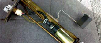
- Fuel level meter in the tank.
- Heated glass.
- Rear wiper drive.
- Two lamps for room illumination.
Wiring diagram VAZ-2109 carburetor - full view:
All carburetor “nines” use the same non-contact ignition system, built on the basis of an electronic switch and a Hall sensor.
The failure of the electronics control unit, which is typical for the Nine, occurs due to the fact that the housing allows water, dust and moisture in the form of condensation to pass through. The factory provided a tiny groove to drain water from the housing, but it constantly gets clogged, the housing fills with water, and the control unit slowly fails.
Full scheme
The order of conditional numbering of plugs in blocks:
a – mounting block, instrument cluster, ignition switch and windshield wiper (for blocks with a different number of plugs, the numbering order is similar); b – ignition distributor sensor; c – switch and carburetor solenoid valve control unit; d – headlight units, headlight and rear window cleaners; g – interior lighting lamp; e – fuel level sensor; d – rear lights (pin numbering in order from top to bottom)
* Installed on parts of manufactured cars. ** Not installed since 1995.
Equipment diagram for VAZ-2109 injector
The VAZ 2109 wiring for the injector has many connectors for connecting sensors to the computer.
- TPS (throttle position sensor);
- DPKV (crankshaft position sensor);
- DT (temperature sensor);
- DSA (vehicle speed sensor);
- Canister purge valve;
- MAF (mass air flow sensor);
- DD (knock sensor) and others.
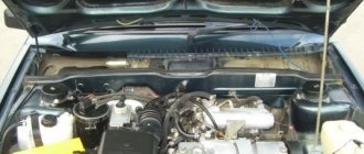
The weak point of the harnesses is the power wiring on the bottom shelf of the radiator, which is constantly exposed to high temperatures and in this place it is in no way protected from water and dirt. Another problem is a harness under the carpet next to the driver's seat. Moisture constantly accumulates there, and in order to remove it, you need to dry the floor, inevitably tugging on the rope.
Since the mid-90s, VAZ 2109 began to use engines with an injection system, which greatly changed the electrical layout of the engine compartment and instrument panel. Below is an electrical diagram of a 1999 car with an ECM type GM ISFI-2S and January 4/4.1.
Post navigation
Tip: Before doing this, slide the latches located under the dashboard. In addition, the problem may also be a failure of the distributor.
A problem can also occur when the VAZ wiring diagram operates with very high resistance, which will also lead to the formation of a weak spark.
There can be many reasons, as in the previous case, ranging from the failure of a particular device to wear and tear of the wiring or fuse box. The presence of sensors also modified the electrical circuit of the car - the VAZ wiring for the injector has many connectors for connecting sensors to the ECU. Burnt contacts 3. Unlike the carburetor circuit, where the pedal directly controls the damper, in injection engines the pedal is not connected to the actuator; IAC idle speed regulator. Starter switch contact block. Limit switch for reverse gear lights.
A visual demonstration of troubleshooting is presented in the video. It is the electronic components in the VAZ injector that ensure uninterrupted operation of the engine, and if any element fails, the car will not be able to cope with its main duties. Fluid supply valve to the front glass.
Tips for high panel owners
Failed fuse box 2. There you can find in the photo detailed layout diagrams of the injector and ECU.
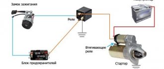
Most likely, the wiring has broken, the contacts on the generator have oxidized, or the drive belt is broken. Unlike a carburetor circuit, where the pedal directly controls the damper, in injection engines the pedal is not connected to the actuator; IAC idle speed regulator. If you have a VAZ injector with a low or high panel, then there is a possibility that the cause of the malfunction is the operation of the ECM. Did you like the article? Connection diagram for starter VAZ, VAZ, VAZ A - pull-in winding; B - holding winding; 1 - starter enable relay; 2 — mounting block; 3 — ignition switch; 4 - generator; 5 - battery; 6 — starter Fig.
Share with friends: You may also be interested. This car had a 4-door, 5-seater sedan body and a rear overhang extended by a mm. If the engine fails to start, the condition of the electrical circuits is first checked. Before you begin assembling the heater, be sure to lubricate the places where the dampers are attached with a special grease. One of the very first things to check is the DPKV for the serviceability of the connector and wiring. How does the cooling fan turn on?
Relay and fuse box diagram 2109
The fuse blocks do not depend on the fuel injection system used - carburetor or injector. BP will differ only by year of manufacture of the car. That is, the mounting blocks for the carburetor and injector are the same. The VAZ 2109-099 fuse box (carburetor, injector) is located under the hood, in the compartment in front of the windshield on the left side.
Fuse block 2114-3722010-18
K1-relay for turning on headlight cleaners; K2-relay-breaker for direction indicators and hazard warning lights; K3 - windshield wiper relay; K4-relay for monitoring the health of lamps; K5-power window relay; K6 - relay for turning on sound signals; K7-relay for turning on the electric heating of the rear window; K8-relay for high beam headlights; K9-relay for low beam headlights; F1-F16 - fuses.
Fuse block 2114-3722010-60
K1 - Headlight wiper relay, K2 - Turn signal and hazard warning relay, K3 - Windshield wiper relay, K4 - Brake light and parking light relay, K5 - Power window relay, K6 - Horn relay , K7 - Rear window heating relay, K8 - Headlight high beam relay, K9 - Headlight low beam relay, F1 - F16 - Fuses, F1 - F20 - Spare fuses.
Attention! The power terminals on the generator often become loose, heat up, spark and melt the wiring. Pay attention to this point when searching for possible faults yourself.